Microelectronic Circuits II. Ch 6 : Building Blocks of Integrated-Circuit Amplifier
|
|
|
- Clarence Ford
- 5 years ago
- Views:
Transcription
1 Micrelectrnic Circuits II Ch 6 : Building Blcks f Integrated-Circuit Amplifier 6.1 IC Design Philsphy 6.A Cmparisn f the MOSFET and the BJT 6.2 The Basic Gain Cell CNU EE 6.1-1
2 Intrductin Basic building blcks f IC (Integrated Circuit) Amplifiers - design philsphy f integrated circuits : difference frm discrete circuits - cmparisn between MOSFET & BJT circuits à Appendix 6.A - basic gain cell f IC amplifiers à current-surce-laded cmmn-surce (cmmn -emitter) amplifier - cascde amplifier & cascde current surce - current mirrrs circuits à biasing and lad elements IC Design Philsphy - limited chip area à avid large-valued resistrs & capacitrs (cupling & bypass) - use MOS transistrs nly & small MOS capacitrs in the picfarad - Present CMOS IC prcessing technlgy (2009) * 45-nm minimum channel length * dc vltage supply : 1 à reduced pwer dissipatin * verdrive vltage : 0.1 ~ 0.2 à currently the mst widely used IC technlgy fr analg, digital & mixed circuit - Biplar circuit * higher utput currents * higher reliability : suitable fr autmtive industry CNU EE 6.1-2
3 Typical values f MOSFET parameters Table 6.A.1 Typical alues f CMOS Device Parameters 0.8µm 0.5 µm 0.25 µm 0.18 µm 0.13 µm Parameter NMOS PMOS NMOS PMOS NMOS PMOS NMOS PMOS NMOS PMOS t x (nm) C x (ff/µm 2 ) µ(cm 2 / s) µc x (µa/ 2 ) t0 () DD () A (/µm) C υ (ff/µm) CNU EE 6.1-3
4 Typical alues f MOSFET Parameters Typical values f MOSFET parameters (submicrn MOS) - Classificatin by the minimum allwed channel length L min : L 0.8 mm à 0.13-mm cmmercially available à 90-, 65, 45-nm prcess (22-nm) - Reduced L min à higher speed r wider bandwidth, 2.3 billin transistrs nt ne chip - Oxide thickness, t x à mm ( mm) - C x ~ 1/t x à increased C x - Increased transcnductance parameters k n/ m n C x, k p/ m p C x à achieves required level f bias current at lwer verdrive vltage à higher transcnductance - Threshld vltage tn & tp : à 0.3 ~ Pwer supply DD : 5 à 1.3 fr 0.13-mm prcess à reduced pwer dissipatin à much larger number f transistrs in the IC chip - Overdrive vltage O : 0.1 ~ 0.2 ( GS t + O ) à saturatin mde : DS > O - prnunced channel length mdulatin effect à A/ decrease, A A/ L decrease à lw utput resistance - higher perating speeds & wider amplifier bandwidth : f T ~ 10GHz CNU EE 6.1-4
5 Typical values f IC BJT parameters Table 6.A.2 Typical alues fr BJTs¹ Standard High-ltage Prcess Advanced Lw-ltage Prcess Parameter npn Lateral pnp npn Lateral pnp A E (µm 2 ) I S (A) β 0 (A/A) A () CE0 () τ F 0.35ns 30ns 10ps 650ps C je0 1pF 0.3pF 5fF 14fF C µ0 0.3pF 1pF 5fF 15fF r x (Ω) CNU EE 6.1-5
6 Typical alues f IC BJT Parameters Typical values f IC BJT parameters (lw vltage prcess) - standard, ld prcess : high-vltage (H) prcess advanced, mdern prcess : lw-vltage (L) prcess - lateral pnp is much inferir t the vertical npn : lw b & large frward transit time t F à higher C de à unity-gain frequency f T is 2 rders f magnitude lwer than npn - dramatic reductin in device size in the advanced lw-vltage prcess à scale current I S reduces by 3 rders f magnitude à base width W B : rder f 0.1 mm à dramatic increase in speed : t F 10 ps (H prcess t F 0.35 ns) à f T : 10 ~ 20 GHz (H prcess 400~600 MHz) - Early vltage A : 35 - Cllectr-emitter vltage : 8 (H prcess : 50 r s) à pwer supply : 15 à 5 r 3.3 CNU EE 6.1-6
7 NMOS npn Circuit Symbl T perate in the Active Mde, tw cnditins have t be satisfied (1) Induce a channel : υ GS t, t Let υ GS t + υ O (2) Pinch-ff channel at drain : υ GD < t r equivalently, υ DS O, O (1) Frward-bias EBJ : υ BE BEn, BEn 0.5 (2) Reverse-bias CBJ : υ BC < BCn, BCn 0.4 r equivalently, υ CE 0.3 CNU EE 6.1-7

8 NMOS FET PMOS FET CNU EE 6.1-8


9 BE > 0 : frward biases EBJ CB > 0 : reverse biases CBJ : switch ff : amplifier : switch n CNU EE 6.1-9
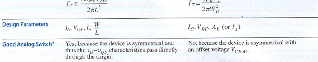
10 Operating cnditins - active mde r active regin : active mde in BJT : saturatin mde in MOSFET - threshld t in MOSFET ~ BE(n) in BJT (almst same) - pinching ff the channel in MOSFET drain ~ reverse biased CBJ in BJT à i D is nearly independent f v D à i C is nearly independent f v C - Asymmetry f BJT à BC(n) is nt equal t BE(n) Symmetrical MOSFET à same t at surce & drain - active mde peratin in BJT & MOSFET à v DS, v CE must be at least 0.1 ~ 0.3 CNU EE

11 NMOS npn Current-ltage Characteristics in the Active Regin 1 W ( ) 2 æ u ö DS id mncx ugs - t ç 1+ 2 L è A ø i G 1 W 2 æ u ö DS mncx uo ç L è A ø 0 i i C B ube / T I Se 1+ i c / b æ u ö CE ç è A ø Lw-Frequency Hybridπ Mdel CNU EE
12 Current ltage Characteristics - i D v GS in MOSFET : square-law characteristic i C v BE in BJT : expnential characteristic (mre sensitive) - Effects f the devices dimensins n its current 1) BJT : area f emitter-base junctin (EBJ), A E à I S variatin in a relatively narrw range : 10 t 1 2) MOSFET : aspect rati W/L variatin in a wide range : 1.0 t 500 à significant design parameter - Dependence f i D (i C ) n v DS (v CE ) in the active regin : channel length mdulatin in MOSFET & base-width mdulatin in BJT à finite input resistance r in the active mde à A in BJT : prcess-technlgy parameter & N relatin w/ dimensin A in MOSFET A/ L : L is design parameter - Gate current in MOSFET 0 & R in lking int the gate infinite finite base current in BJT : i B i C /b & finite R in lking int the base CNU EE
13 Ex. 6.A.1 (a) NMOS w/ W/L10 in 0.18 mm prcess. Find O & GS fr I D 100mA, N channel-length mdulatin 1 æ W ö 2 ( ) I m C 2 ç L è ø D n x O O O 0.23 GS tn + O by I D, W/L & m n C x 387 ma/ 2 frm Table 6.A.1 (b) Find BE fr npn transistr fabricated by L prcess & w/ I C 100mA, N base-width mdulatin I C I e S BE / T by I C, I S 6x10-18 A frm Table 6.A.2 BE ln CNU EE
 ç L è ø m n x O æ W ö g 2( m C ) ç I L è ø m n x D g I / m C T CNU EE 6.1-14")
14 NMOS npn Lw-Frequency T Mdel Transcnductance g m ( ) g I / / 2 m D O æ W ö g ( m C ) ç L è ø m n x O æ W ö g 2( m C ) ç I L è ø m n x D g I / m C T CNU EE
15 Lw-Frequency Small-Signal Mdels - BJT mdel finite base current (finite b) à r p in the hybrid-p mdel à unequal i E & i C in the T mdel, a < 1 - LF mdel f MOSFET BJT w/ b inf. (a1) - pen-circuit vltage gain frm G(B) t D(C) w/ grunded S(E) : -g m r g m r : maximum gain available frm a single transistr f either type à intrinsic gain A 0 - Bdy effect in the MOSFET bdy (substrate) : 2 nd gate bdy-surce vltage v bs à drain current g mb v bs (g mb : bdy transcnductance) g mb cg m (c 0.1 ~ 0.2) Transcnductance - g m in BJT I C / T ( T ~ 25 m at R.T à depend nly n I C ) - g m in MOSFET depends n I D, O & W/L 1 st : similar t BJT g m but small ( O /2 ~ 0.05 ~ 0.15) 2 nd : prprtinal t O fr a given W/L. higher g m by higher O but O is limited by DD 3 rd : prprtinal t I D fr a given W/L. g m in BJT is directly prprtinal t I C CNU EE
16 NMOS npn Output Resistance r L r I r / I ' A A / D I D A C Intrinsic Gain A 0 g m r ( ) A / / 2 A A A ' 2 AL O O ' 2 A 2mn x I C WL D A 0 A / T Input Resistance with Surce (Emitter) Grunded r p b /g m CNU EE
17 Output resistance - rati f A t the bias current (I D r I C ) - r is inversely prprtinal t the bias current Intrinsic gain A 0 - A 0 f BJT : rati f prcess parameter A (35 t 130) & physical parameter T à independent f the device junctin area & f the perating current (1000~5000/) - A 0 f MOSFET 1 st : denminatr O /2 is a design parameter. (>> T ) numeratr A is prcess- & device-dependent, steadily decreasing à 20 ~40/ fr a mdern shrt-channel technlgy 3 rd : A 0 fr a given A/, m n C x & W/L is inversely prprtinal t I D A 0 vs. I D plt - gain A 0 increase as I D is lwered - higher gain A 0 at the lwer bias currents à lwer g m, lwer capacitive lad drive capability, decrease in bandwidth CNU EE
18 Ex. 6.A.2 Cmpare g m, R in at G (B), r & A 0 fr 0.25-mm NMOS and L-tech. npn Tr. Assume I D (I C ) 100mA. Fr L0.4mm, W4mm NMOS, specify O. Fr NMOS 1 æ W ö 2 ( ) I m C 2 ç L è ø D n x O O Thus, O 0.27 æ W ö g 2( m C ) ç I L è ø m n x D mA / R in A0 gmr / Fr npn transistr r ' AL kW I 0.1 D g m IC 0.1mA 4mA/ T 100 Rin rp b0 / gm 25kW 4mA/ r A kW I 0.1mA C A0 gmr / CNU EE


19 NMOS npn high- Frequency Mdel CNU EE

20 CNU EE
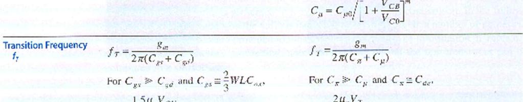
21 High-Frequency Operatin - unity-gain frequency (transitin frequency) f T * a measure f the intrinsic bandwidth f the transistr itself w/ capacitive lad effect * inversely prprtinal t the square f L fr MOSFET & W B fr BJT * f T f BJT is entirely prcess determined but f T f MOSFET is prprtinal t O : higher-lw frequency gain by lw O but wider bandwidth by high O è trade-ff between gain and bandwidth * f T f npn Tr. in L prcess : 10 ~ 20 GHz, NMOS in 0.18-mm prcess : 5~15GHz Effect f a capacitive lad n the bandwidth f CS (CE) amplifier - Assume frequencies f interest << f T à neglects the transistr internal capacitances - CS amplifier w/ capacitive lad C L * vltage gain frm gate t drain 1 r sc gmr L -g A u 1 - m O -g mgs ( ro // CL ) gs gs 1+ sclr r + - gain A v at lw frequency : g m r A 0 - freq. respnse f single-time-cnstant (STC) lw-pass type w/ a break (ple) freq. at 1 w P C r L CNU EE sc L
22 - unity-gain frequency r, gain-bandwidth prduct w t : rati f g m and C L * the gain crsses the 0-dB line at w t 1 gm wt A0w P ( gmr ) w t C r C - Fr a given C L, higher g m à larger gain-bandwidth prduct à bandwidth increases as bias current is increased L CNU EE L
23 Design Parameters - design parameters fr BJT : I C, BE, & I S (r area f emitter-base junctin A E ) * I C is expnentially related t BE (D BE 60m à 10 changes in I C ) * A E can vary ver the narrw range à I C is nly effective design parameter - design parameter fr MOSFET : I D, O, L & W * trade ff in L value - higher speed (wider bandwidth) à lwer L - higher intrinsic gain à larger L - L : 25% t 50% greater than L min * O : range f 0.2 ~ 0.4 * fr a given L & O, I D is prprtinal t W/L - I D (r W/L) : N bearing n A 0 & f T - I D affects g m à gain-bandwidth prduct - dc gain remains unchanged, increasing W/L (r I D ) increases bandwidth prprtinally (g m ~ I D & r ~ 1/I D ) CNU EE
24 Ex. 6.A.3 (a) npn transistr in L prcess w/ C m~c m0. Find g m, r, A 0, C de, C je,c p, C m, f T & f t in 1-pF lad capacitance fr I C 10mA, 100mA & 1mA. g m IC IC A 35 40I A/ r I I W C A0 T C C A / T C t g I I F C 2C je0 10 ff de F m C C + p de je Cm 0 5fF C C C f T 2p g m m m ft p CL 2p 1 10 ( Cp Cm ) g g I C g m (ma/) r (kω) A 0 (/) C de (ff) CNU EE C je (ff) C π (ff) C µ (ff) f T (GHz) f t (MHz) 10µA µA mA
25 (b) NMOS in 0.25-mm prcess w/ L0.4mm, O Find W/L, g m, r, A 0, C gs, C gd,c p, f T & f t in 1-pF lad capacitance fr I D 10mA, 100mA & 1mA. 1 W I m C 2 L 2 D n x O 1 W 1 W I 2 L 16 L D g m I D I D 8I D A/ / / 2 O r ' AL W A0 gmr 16 / I I I D D D 2 2 C gs WLCx + C u W W 3 3 C C 0.6W gd u f T 2p g m ( C gs + C gd ) f t g m 2pC L I D W/L g m (ma/) r (kω) A 0 (/) C gs (ff) C gd (ff) f T (GHz) f t (MHz) 10µA µA mA CNU EE
 lad R à much higher gain current-surce laded r active")
26 Basic Gain Cell CS and CE amplifier with Current-surce lads - basic gain cell in an IC amplifier CS r CE transistr laded with a cnstant-current surce à replace R D & R C with cnstant-current surce - difficulty fr R with precise values in IC à current surces using transistrs - current surce CS & CE amplifiers w/ a very high (ideally infinite) lad R à much higher gain current-surce laded r active laded CNU EE
27 CS & CE Amplifier w/ Current-Surce Lads Small-signal analysis f the active-laded CS & CE amplifiers - Q 1 is biased at I D I & I C I - DC bias vltage DS & GS ( CE & BE ) are determined by negative feedback à MOSFET is biased in saturatin regin & BJT is in active regin à refer t active regin fr MOSFET & BJT - Small-signal equivalent circuit : ideal current-surce à infinite resistance à pen circuit - active-laded CS amplifier R A -g r R in v - active-laded CE amplifier m r R A -g r R r in r p v m - bth vltage gains g m r à maximum gain btainable in a CS r CE amplifier à intrinsic gain A CNU EE
28 CNU EE Intrinsic Gain A Intrinsic gain f BJT - Early vltage A : 5 ~ 35 (100 ~ 130), thermal vltage T : rm temperature à A : 200 ~ 5000 / & independent f transistr junctin area & its bias current T A m C A T C m r g A I r I g Intrinsic gain f MOSFET - Overdrive vltage O : 0.15 ~ 0.3 à O /2 ~ 3 t 6 higher than T - A is increased by using a lnger L & lwer O à decrease in amplifier bandwidth à A : 20 ~ 40 /, an rder f magnitude lwer than a BJT O A O A D A D A D x n O D m L A I L I r I L W C I g / / 2 2 ) ( 2 2 m
29 Effect f Output Resistance f Current-Surce Lad Current-surce lad à PMOS transistr biased in the saturatin regin t prvide the required current I CNU EE
30 Effect f Output Resistance f Current-Surce Lad - Q 2 large-signal MOSFET mdel: I 1 m p 2 æw ö ( C ) ç [ - - ] x è L ø 2 DD G tp 2 r 2 A2 I - current-surce lad has a finite utput resistance r 2 such as (b) - ltage gain is reduced t g m1 (r 1 r 2 ) frm g m1 r 1 v A º -g ( r r ) v v i m If Q 1 & Q 2 has the same Early vltage, r 1 r 2 & half gain A v 1-2 g m r A CNU EE

31 Increasing Gain f the Basic Cell Hw can we increase the vltage gain btained frm the basic gain cell? - raise the level f the utput resistance f bth the amplifying & lad transistr - CS amplifying Tr. Q 1 + utput equivalent circuit - A black bx between D f Q 1 & a new utput terminal d 2 - The black bx passes the same Q 1 utput current g m1 v i but with the utput resistance increased by a factr K à current buffer CNU EE
 r cmmn base (CB) amplifier : unity current gain - ltage buffer passes the vltage but lwers the resistance level à surce (CD) & emitter (CE) fllwer - Hw t raise the")
32 Increasing Gain f the Basic Cell The black bx passes the current g m1 v i right thrugh but raise the resistance level by a factr K à current buffer - Current buffer passes the current but raises the resistance level à cmmn gate (CG) r cmmn base (CB) amplifier : unity current gain - ltage buffer passes the vltage but lwers the resistance level à surce (CD) & emitter (CE) fllwer - Hw t raise the utput resistance f the amplifying transistr and current-surce lad à use a current buffer - Placing a CG (r CB) circuit n tp f the CS (r CE) amplifying transistr t implement the current-buffering actin à cascding CNU EE
COMPARISON OF THE MOSFET AND THE BJT:
 COMPARISON OF THE MOSFET AND THE BJT: In this section we present a comparison of the characteristics of the two major electronic devices: the MOSFET and the BJT. To facilitate this comparison, typical
A Basis for LDO and It s Thermal Design
 A Basis fr LDO and It s Thermal Design Hawk Chen Intrductin The AIC LDO family device, a 3-terminal regulatr, can be easily used with all prtectin features that are expected in high perfrmance vltage regulatin
Lecture 11. Active Devices -- BJT & MOSFET. Agenda: MOSFET Small-signal Model. Active Devices -- BJT & MOSFET. Cross-section
 EEL6935 Advanced MEMS (Spring 2005) Intructr: Dr. Huikai Xie Device -- BJT & MOSFET Agenda: Lecture Amplifier Baic Device mdel Current mirrr Single-tage amplifier Operatinal amplifier cnfiguratin Cr-ectin
Integrated Circuit Amplifiers. Comparison of MOSFETs and BJTs
 Integrated Circuit Amplifiers Comparison of MOSFETs and BJTs 17 Typical CMOS Device Parameters 0.8 µm 0.25 µm 0.13 µm Parameter NMOS PMOS NMOS PMOS NMOS PMOS t ox (nm) 15 15 6 6 2.7 2.7 C ox (ff/µm 2 )
Output Stages. Microelectronic Circuits. Ching-Yuan Yang. National Chung-Hsing University Department of Electrical Engineering.
 Micrelectrnic Circuits Output Stages Ching-Yuan Yang Natinal Chung-Hsing University Department f Electrical Engineering Outline Classificatin f Output Stages Class A Output Stage Class B Output Stage Class
The fan-in of a logic gate is defined as the number of inputs that the gate is designed to handle.
 8 Lgic Families Characteristics f Digital IC Threshld Vltage The threshld vltage is defined as that vltage at the input f a gate which causes a change in the state f the utput frm ne lgic level t the ther.
DEI 1028 Voltage Clamping Circuit
 Device Engineering Incrprated 385 East Alam Drive handler, AZ 85225 Phne: (48) 33-822 Fax: (48) 33-824 E-mail: admin@deiaz.cm DEI 128 ltage lamping ircuit Features Prtectin fr pwer electrnics n 28D avinics
CM5530 GENERAL DESCRIPTION APPLICATIONS TYPICAL APPLICATION CIRCU. Rev.1.0 0
 FEATURES Quasi-Resnant Primary Side Regulatin (QR-PSR) Cntrl with High Efficiency Multi-Mde PSR Cntrl Fast Dynamic Respnse Built-in Dynamic Base Drive Audi Nise Free Operatin ±4% CC and C Regulatin Lw
Microelectronic Circuits II. Ch 10 : Operational-Amplifier Circuits
 Microelectronic Circuits II Ch 0 : Operational-Amplifier Circuits 0. The Two-stage CMOS Op Amp 0.2 The Folded-Cascode CMOS Op Amp CNU EE 0.- Operational-Amplifier Introduction - Analog ICs : operational
Building Blocks of Integrated-Circuit Amplifiers
 Building Blocks of ntegrated-circuit Amplifiers 1 The Basic Gain Cell CS and CE Amplifiers with Current Source Loads Current-source- or active-loaded CS amplifier Rin A o R A o g r r o g r 0 m o m o Current-source-
EEEE 381 Electronics I
 EEEE 381 Electrnics I Lab #4: MOSFET Differential Pair with Active Lad Overview The differential amplifier is a fundamental building blck in electrnic design. The bjective f this lab is t examine the vltage
Operational Amplifiers High Speed Operational Amplifiers
 F Electrnics: Operatinal Amplifiers Page 11.1 Operatinal Amplifiers High Speed Operatinal Amplifiers Operatinal amplifiers with 3 db bandwidths f up t 1.5 GHz are nw available, such peratinal amplifiers
Multistage Amplifiers
 Multistage Amplifiers Single-stage transistor amplifiers are inadequate for meeting most design requirements for any of the four amplifier types (voltage, current, transconductance, and transresistance.)
Soldering Temperature, for 10 seconds 300 (0.063 in. (1.6mm) from case )
 from case )") INSULATED GATE BIPOLAR TRANSISTOR PD - 9587 IRG4PH40UPbF Ultra Fast Speed IGBT Features UltraFast: Optimized fr high perating frequencies up t 40 khz in hard switching, >200 khz in resnant mde New IGBT
INSULATED GATE BIPOLAR TRANSISTOR PD - 9587 IRG4PH40UPbF Ultra Fast Speed IGBT Features UltraFast: Optimized fr high perating frequencies up t 40 khz in hard switching, >200 khz in resnant mde New IGBT
IRG4BC20FPbF Fast Speed IGBT
 PD - 95742 INSULATED GATE BIPOLAR TRANSISTOR IRG4BC20FPbF Fast Speed IGBT Features C Fast: Optimized fr medium perating frequencies ( -5 khz in hard switching, >20 khz in resnant mde). Generatin 4 IGBT
UNIT-1 Bipolar Junction Transistors. Text Book:, Microelectronic Circuits 6 ed., by Sedra and Smith, Oxford Press
 UNIT-1 Bipolar Junction Transistors Text Book:, Microelectronic Circuits 6 ed., by Sedra and Smith, Oxford Press Figure 6.1 A simplified structure of the npn transistor. Microelectronic Circuits, Sixth
Unit 3: Integrated-circuit amplifiers (contd.)
") Unit 3: Integrated-circuit amplifiers (contd.) COMMON-SOURCE AND COMMON-EMITTER AMPLIFIERS The Common-Source Circuit The most basic IC MOS amplifier is shown in fig.(1). The source of MOS transistor is
Unit 3: Integrated-circuit amplifiers (contd.) COMMON-SOURCE AND COMMON-EMITTER AMPLIFIERS The Common-Source Circuit The most basic IC MOS amplifier is shown in fig.(1). The source of MOS transistor is
BJT Amplifier. Superposition principle (linear amplifier)
") BJT Amplifier Two types analysis DC analysis Applied DC voltage source AC analysis Time varying signal source Superposition principle (linear amplifier) The response of a linear amplifier circuit excited
BJT Amplifier Two types analysis DC analysis Applied DC voltage source AC analysis Time varying signal source Superposition principle (linear amplifier) The response of a linear amplifier circuit excited
Review of Electronic I. Lesson #2 Solid State Circuitry Diodes & Transistors Chapter 3. BME Electronics II J.Schesser
 Review f Electrnic I Lessn #2 Slid State Circuitry Dides & Transistrs Chapter 3 ME 498008 Electrnics II 55 Dides Typical Dide VI Characteristics Frward ias Regin Reverse ias Regin Reverse reakdwn Regin
Building Blocks of Integrated-Circuit Amplifiers
 CHAPTER 7 Building Blocks of Integrated-Circuit Amplifiers Introduction 7. 493 IC Design Philosophy 7. The Basic Gain Cell 494 495 7.3 The Cascode Amplifier 506 7.4 IC Biasing Current Sources, Current
6.012 Microelectronic Devices and Circuits
 Page 1 of 13 YOUR NAME Department of Electrical Engineering and Computer Science Massachusetts Institute of Technology 6.012 Microelectronic Devices and Circuits Final Eam Closed Book: Formula sheet provided;
Laboratory #5 BJT Basics and MOSFET Basics
 Laboratory #5 BJT Basics and MOSFET Basics I. Objectives 1. Understand the physical structure of BJTs and MOSFETs. 2. Learn to measure I-V characteristics of BJTs and MOSFETs. II. Components and Instruments
Current Mirrors. Prof. Tai-Haur Kuo, EE, NCKU, Tainan City, Taiwan 4-1
 Current Mirrors Prof. Tai-Haur Kuo, EE, NCKU, Tainan City, Taiwan 4- 郭泰豪, Analog C Design, 08 { Prof. Tai-Haur Kuo, EE, NCKU, Tainan City, Taiwan 4- 郭泰豪, Analog C Design, 08 { Current Source and Sink Symbol
Chapter 6. Single-stage integrated-circuit amplifier
 hapter 6. Single-stage integrated-circuit amplifier ntroduction 6. design philosophy 6. omparison of the MSFET and the BJT 6.3 biasing-current - sources, mirrors and steering circuits 6.4 High-frequency
The Miller Approximation. CE Frequency Response. The exact analysis is worked out on pp of H&S.
 CE Frequency Response The exact analysis is worked out on pp. 639-64 of H&S. The Miller Approximation Therefore, we consider the effect of C µ on the input node only V ---------- out V s = r g π m ------------------
UNIT I BIASING OF DISCRETE BJT AND MOSFET PART A
 UNIT I BIASING OF DISCRETE BJT AND MOSFET PART A 1. Why do we choose Q point at the center of the load line? 2. Name the two techniques used in the stability of the q point.explain. 3. Give the expression
PreLab5 Temperature-Controlled Fan (Due Oct 16)
") PreLab5 Temperature-Cntrlled Fan (Due Oct 16) GOAL The gal f Lab 5 is t demnstrate a temperature-cntrlled fan. INTRODUCTION The electrnic measurement f temperature has many applicatins. A temperature-cntrlled
PreLab5 Temperature-Cntrlled Fan (Due Oct 16) GOAL The gal f Lab 5 is t demnstrate a temperature-cntrlled fan. INTRODUCTION The electrnic measurement f temperature has many applicatins. A temperature-cntrlled
Vds 1. Gnd. Gnd. Key Specifications Symbol Parameter Units Min. Typ. Max.
 Prduct Descriptin Sirenza Micrdevices SDM- W pwer mdule is a rbust impedance matched, single-stage, push-pull Class AB amplifier mdule suitable fr use as a pwer amplifier driver r utput stage. The pwer
F7 Transistor Amplifiers
 Lars Ohlsson 2018-09-25 F7 Transistor Amplifiers Outline Transfer characteristics Small signal operation and models Basic configurations Common source (CS) CS/CE w/ source/ emitter degeneration resistance
Rectifiers convert DC to AC. Inverters convert AC to DC.
 DT23-3 Inverter Ntes 3 January 23. The difference between Rectifiers and Inverters Rectifiers cnvert DC t AC. Inverters cnvert AC t DC. 2. Uses f Inverters Battery Backup. Batteries stre DC. Many appliances
Single-Stage BJT Amplifiers and BJT High-Frequency Model. Single-Stage BJT Amplifier Configurations
 1 Single-Stage BJT Amplifiers and BJT High-Frequency Model Asst. Prof. MONTREE SIRIPRUCHYANUN, D. Eng. Dept. of Teacher Training in Electrical Engineering, Faculty of Technical Education King Mongkut s
INTRODUCTION TO PLL DESIGN
 INTRODUCTION TO PLL DESIGN FOR FREQUENCY SYNTHESIZER Thanks Sung Tae Mn and Ari Valer fr part f this material A M S C Analg and Mixed-Signal Center Cntents Intrductin t Frequency Synthesizer Specificatin
C H A P T E R 5. Amplifier Design
 C H A P T E 5 Amplifier Design The Common-Source Amplifier v 0 = r ( g mvgs )( D 0 ) A v0 = g m r ( D 0 ) Performing the analysis directly on the circuit diagram with the MOSFET model used implicitly.
ACPL-8x7. Data Sheet. Multi-Channel Full-Pitch Phototransistor Optocoupler. Description. Features. Applications
 Data Sheet ACPL-8x7 Multi-Channel Full-Pitch Phttransistr Optcupler Descriptin The ACPL-827 is a DC-input dual-channel, full-pitch phttransistr ptcupler that cntains tw light emitting dides ptically cupled
ECE 255, MOSFET Basic Configurations
 ECE 255, MOSFET Basic Configurations 8 March 2018 In this lecture, we will go back to Section 7.3, and the basic configurations of MOSFET amplifiers will be studied similar to that of BJT. Previously,
Solid State Devices & Circuits. 18. Advanced Techniques
 ECE 442 Solid State Devices & Circuits 18. Advanced Techniques Jose E. Schutt-Aine Electrical l&c Computer Engineering i University of Illinois jschutt@emlab.uiuc.edu 1 Darlington Configuration - Popular
EE380: Exp. 2. Measurement of Op-Amp Parameters and Design/ Verification of an Integrator
 EE380: Exp. 2 Measurement Op-Amp Parameters and Design/ Veriicatin an Integratr Intrductin: An Opamp is a basic building blck a wide range analg circuits. T carry ut design circuits cnsisting ne r mre
55:041 Electronic Circuits
 55:041 Electronic Circuits MOSFETs Sections of Chapter 3 &4 A. Kruger MOSFETs, Page-1 Basic Structure of MOS Capacitor Sect. 3.1 Width = 1 10-6 m or less Thickness = 50 10-9 m or less ` MOS Metal-Oxide-Semiconductor
MOS Field-Effect Transistors (MOSFETs)
") 6 MOS Field-Effect Transistors (MOSFETs) A three-terminal device that uses the voltages of the two terminals to control the current flowing in the third terminal. The basis for amplifier design. The basis
6 MOS Field-Effect Transistors (MOSFETs) A three-terminal device that uses the voltages of the two terminals to control the current flowing in the third terminal. The basis for amplifier design. The basis
Chapter 15 Goals. ac-coupled Amplifiers Example of a Three-Stage Amplifier
 Chapter 15 Goals ac-coupled multistage amplifiers including voltage gain, input and output resistances, and small-signal limitations. dc-coupled multistage amplifiers. Darlington configuration and cascode
MICROELECTRONIC CIRCUIT DESIGN Third Edition
 MICROELECTRONIC CIRCUIT DESIGN Third Edition Richard C. Jaeger and Travis N. Blalock Answers to Selected Problems Updated 1/25/08 Chapter 1 1.3 1.52 years, 5.06 years 1.5 1.95 years, 6.46 years 1.8 113
Voltage Biasing Considerations (From the CS atom toward the differential pair atom) Claudio Talarico, Gonzaga University
 Claudio Talarico, Gonzaga University") Voltage Biasing Considerations (From the CS atom toward the differential pair atom) Claudio Talarico, Gonzaga University Voltage Biasing Considerations In addition to bias currents, building a complete
Voltage Biasing Considerations (From the CS atom toward the differential pair atom) Claudio Talarico, Gonzaga University Voltage Biasing Considerations In addition to bias currents, building a complete
Introduction to Optical Detectors (Nofziger)
") 1 Intrductin t Optical Detectrs (Nfziger) Optical detectrs are at the heart f mst mdern-day ptical systems. They have largely replaced the human eye r tgraic film as the detectin medium. They may be categrized
1 Intrductin t Optical Detectrs (Nfziger) Optical detectrs are at the heart f mst mdern-day ptical systems. They have largely replaced the human eye r tgraic film as the detectin medium. They may be categrized
Advanced Operational Amplifiers
 IsLab Analog Integrated Circuit Design OPA2-47 Advanced Operational Amplifiers כ Kyungpook National University IsLab Analog Integrated Circuit Design OPA2-1 Advanced Current Mirrors and Opamps Two-stage
Code: 9A Answer any FIVE questions All questions carry equal marks *****
 II B. Tech II Semester (R09) Regular & Supplementary Examinations, April/May 2012 ELECTRONIC CIRCUIT ANALYSIS (Common to EIE, E. Con. E & ECE) Time: 3 hours Max Marks: 70 Answer any FIVE questions All
ECE 255, MOSFET Amplifiers
 ECE 255, MOSFET Amplifiers 26 October 2017 In this lecture, the basic configurations of MOSFET amplifiers will be studied similar to that of BJT. Previously, it has been shown that with the transistor
Improving Amplifier Voltage Gain
 15.1 Multistage ac-coupled Amplifiers 1077 TABLE 15.3 Three-Stage Amplifier Summary HAND ANALYSIS SPICE RESULTS Voltage gain 998 1010 Input signal range 92.7 V Input resistance 1 M 1M Output resistance
Property of Lite-On Only
 FEATURES. This specificatin shall be applied t phtcupler Mdel N. April 2 LTV-852/LTV-8D52 as an ptin. 2. Applicable Mdels (Business dealing name) * Dual-in-line package : LTV852-V / LTV8D52-V * Wide lead
EE105 Fall 2015 Microelectronic Devices and Circuits
 EE105 Fall 2015 Microelectronic Devices and Circuits Prof. Ming C. Wu wu@eecs.berkeley.edu 511 Sutardja Dai Hall (SDH) 11-1 Transistor Operating Mode in Amplifiers Transistors are biased in flat part of
(c) Compute the maximum instantaneous power dissipation of the transistor under worst-case conditions. Hint: Around 470 mw.
 Compute the maximum instantaneous power dissipation of the transistor under worst-case conditions. Hint: Around 470 mw.") Hmewrk b ECE (F) 8 prblems fr 00 pts Due Oct A. Unidirectinal Current Bster Analysis ) Cnsider the current bster shwn in Fig.. Assume an ideal p amp with V CC = 9V. The transistr is a N904, and use data
Hmewrk b ECE (F) 8 prblems fr 00 pts Due Oct A. Unidirectinal Current Bster Analysis ) Cnsider the current bster shwn in Fig.. Assume an ideal p amp with V CC = 9V. The transistr is a N904, and use data
Common Gate Stage Cascode Stage. Claudio Talarico, Gonzaga University
 Common Gate Stage Cascode Stage Claudio Talarico, Gonzaga University Common Gate Stage The overdrive due to V B must be consistent with the current pulled by the DC source I B careful with signs: v gs
55:041 Electronic Circuits
 55:041 Electronic Circuits Mosfet Review Sections of Chapter 3 &4 A. Kruger Mosfet Review, Page-1 Basic Structure of MOS Capacitor Sect. 3.1 Width 1 10-6 m or less Thickness 50 10-9 m or less ` MOS Metal-Oxide-Semiconductor
A 2V CMOS Capacitorless Current-Tunable All-Pass Filter using Current Mirrors
 Thammasat Int. J. Sc. Tech., Vl.6, N.l, January-April 2001 A 2V CMOS Capacitrless Current-Tunable All-Pass Filter using Current Mirrrs Banlue Srisuchinwng and Adisrn Leelasantitham Electrical Engineering
Chapter 12 Opertational Amplifier Circuits
 1 Chapter 12 Opertational Amplifier Circuits Learning Objectives 1) The design and analysis of the two basic CMOS op-amp architectures: the two-stage circuit and the single-stage, folded cascode circuit.
Homework Assignment 12
 Homework Assignment 12 Question 1 Shown the is Bode plot of the magnitude of the gain transfer function of a constant GBP amplifier. By how much will the amplifier delay a sine wave with the following
Lecture 21 - Multistage Amplifiers (I) Multistage Amplifiers. November 22, 2005
 Multistage Amplifiers. November 22, 2005") 6.02 Microelectronic Devices and Circuits Fall 2005 Lecture 2 Lecture 2 Multistage Amplifiers (I) Multistage Amplifiers November 22, 2005 Contents:. Introduction 2. CMOS multistage voltage amplifier 3.
6.02 Microelectronic Devices and Circuits Fall 2005 Lecture 2 Lecture 2 Multistage Amplifiers (I) Multistage Amplifiers November 22, 2005 Contents:. Introduction 2. CMOS multistage voltage amplifier 3.
List... Package outline... Features Mechanical data... Maximum ratings... Electrical characteristics Rating and characteristic curves...
 PNP SMD Transistr BC87-6/BC87-25/BC87-4 Frmsa MS List List... Package utline... 2 Features... 2 Mechanical data... Maximum ratings... 2 2 Electrical characteristics... 3 Rating and characteristic curves...
QUESTION BANK for Analog Electronics 4EC111 *
 OpenStax-CNX module: m54983 1 QUESTION BANK for Analog Electronics 4EC111 * Bijay_Kumar Sharma This work is produced by OpenStax-CNX and licensed under the Creative Commons Attribution License 4.0 Abstract
Summary of Lecture Notes on Metal-Oxide-Semiconductor, Field-Effect Transistors (MOSFETs)
") Mani Vaidyanathan 1 Summary of Lecture Notes on Metal-Oxide-Semiconductor, Field-Effect Transistors (MOSFETs) Introduction 1. We began by asking, Why study MOSFETs? The answer is, Because MOSFETs are the
Mani Vaidyanathan 1 Summary of Lecture Notes on Metal-Oxide-Semiconductor, Field-Effect Transistors (MOSFETs) Introduction 1. We began by asking, Why study MOSFETs? The answer is, Because MOSFETs are the
Reading. Lecture 33: Context. Lecture Outline. Chapter 9, multi-stage amplifiers. Prof. J. S. Smith
 eading Lecture 33: Chapter 9, multi-stage amplifiers Prof J. S. Smith Context Lecture Outline We are continuing to review some of the building blocks for multi-stage amplifiers, including current sources
CPC1025NTR. 4 Pin SOP OptoMOS Relay
 4 Pin SOP OptMOS Relay Units Lad Vltage 4 V Lad Current 12 ma Typ. R ON 2 Ω Features Small 4 Pin SOP Package Lw Drive Pwer Requirements (TTL/CMOS Cmpatible) N Mving Parts High Reliability Arc-Free With
karma UK Sales: RETAIL Price List - Valid From January 2017
 RETAIL Price List - Valid Frm January 2017 N 519 Reference Surce The Mark Levinsn 519 is a cmplete, mdern music player fr tday s music lver. It cmbines wireless and wired music streaming with a traditinal
Week 7: Common-Collector Amplifier, MOS Field Effect Transistor
 EE 2110A Electronic Circuits Week 7: Common-Collector Amplifier, MOS Field Effect Transistor ecture 07-1 Topics to coer Common-Collector Amplifier MOS Field Effect Transistor Physical Operation and I-V
Laboratory: Introduction to Mechatronics. Instructor TA: Edgar Martinez Soberanes Lab 1.
 Labratry: Intrductin t Mechatrnics Instructr TA: Edgar Martinez Sberanes (eem370@mail.usask.ca) 2015-01-12 Lab 1. Intrductin Lab Sessins Lab 1. Intrductin Read manual and becme familiar with the peratin
Department of Electrical Engineering IIT Madras
 Department of Electrical Engineering IIT Madras Sample Questions on Semiconductor Devices EE3 applicants who are interested to pursue their research in microelectronics devices area (fabrication and/or
5. Experimental Results
 5. xperimental Results Prttype mdels f the duble spherical helix the hemispherical helix studied in Sectins 4.3.2 4.4 were cnstructed measured. Fabricatin f these antennas measurement f their radiatin
Lecture 33: Context. Prof. J. S. Smith
 Lecture 33: Prof J. S. Smith Context We are continuing to review some of the building blocks for multi-stage amplifiers, including current sources and cascode connected devices, and we will also look at
Field-Effect Transistor (FET) is one of the two major transistors; FET derives its name from its working mechanism;
 is one of the two major transistors; FET derives its name from its working mechanism;") Chapter 3 Field-Effect Transistors (FETs) 3.1 Introduction Field-Effect Transistor (FET) is one of the two major transistors; FET derives its name from its working mechanism; The concept has been known
Chapter 3 Field-Effect Transistors (FETs) 3.1 Introduction Field-Effect Transistor (FET) is one of the two major transistors; FET derives its name from its working mechanism; The concept has been known
Compound Semiconductors; GaN and SiC, Separating Fact from Fiction in both Research and Business
 6/25/2013 Cmpund Semicnductrs; and, Separating Fact frm Fictin in bth Research and Business Prfessr Umesh Mishra, Ph.D. Redefining Energy Efficiency Cmpund semicnductrs separating Fact frm Fictin Why d
LINE POWER SUPPLIES Low-Loss Supplies for Line Powered EnOcean Modules
 Lw-Lss Supplies fr Line Pwered EnOcean Mdules A line pwer supply has t ffer the required energy t supply the actuatr electrnic and t supply the EnOcean TCM/RCM radi cntrl mdule. This paper cntains sme
Lecture 020 ECE4430 Review II (1/5/04) Page 020-1
 Page 020-1") Lecture 020 ECE4430 Review II (1/5/04) Page 020-1 LECTURE 020 ECE 4430 REVIEW II (READING: GHLM - Chap. 2) Objective The objective of this presentation is: 1.) Identify the prerequisite material as taught
Lecture 020 ECE4430 Review II (1/5/04) Page 020-1 LECTURE 020 ECE 4430 REVIEW II (READING: GHLM - Chap. 2) Objective The objective of this presentation is: 1.) Identify the prerequisite material as taught
Input-Series Two-Stage DC-DC Converter with Inductor Coupling
 Input-Series w-stage DC-DC Cnverter with Inductr Cupling ing Qian Wei Sng Brad Lehman Nrtheastern University Dept. Electrical & Cmputer Engineering Bstn MA 0 USA Abstract: his paper presents an input-series
Chapter 8 Differential and Multistage Amplifiers
 1 Chapter 8 Differential and Multistage Amplifiers Operational Amplifier Circuit Components 2 1. Ch 7: Current Mirrors and Biasing 2. Ch 9: Frequency Response 3. Ch 8: Active-Loaded Differential Pair 4.
MOSFET Amplifier Configuration. MOSFET Amplifier Configuration
 MOSFET Amplifier Configuration Single stage The signal is fed to the amplifier represented as sig with an internal resistance sig. MOSFET is represented by its small signal model. Generally interested
Lecture 020 ECE4430 Review II (1/5/04) Page 020-1
 Page 020-1") Lecture 020 ECE4430 Review II (1/5/04) Page 020-1 LECTURE 020 ECE 4430 REVIEW II (READING: GHLM - Chap. 2) Objective The objective of this presentation is: 1.) Identify the prerequisite material as taught
Lecture 020 ECE4430 Review II (1/5/04) Page 020-1 LECTURE 020 ECE 4430 REVIEW II (READING: GHLM - Chap. 2) Objective The objective of this presentation is: 1.) Identify the prerequisite material as taught
CS and CE amplifiers with loads:
 CS and CE amplifiers with loads: The Common-Source Circuit The most basic IC MOS amplifier is shown in fig.(1). The source of MOS transistor is grounded, also the drain resistor RD replaced by a constant-current
High Efficiency Frequency Tunable Inverse Class-E Amplifier in VHF Band
 High Efficiency Frequency Tunable Inverse Class-E Amplifier in VHF Band Kumh Natinal Institute f Technlgy, 1 Yangh-Dng, Gumi, Gyungbuk, 730-701, Krea yungk@kumh.ac.kr Abstract This paper prpses the use
Microelectronic Devices and Circuits- EECS105 Final Exam
 EECS105 1 of 13 Fall 2000 Microelectronic Devices and Circuits- EECS105 Final Exam Wednesday, December 13, 2000 Costas J. Spanos University of California at Berkeley College of Engineering Department of
ECE 442 Solid State Devices & Circuits. 15. Differential Amplifiers
 ECE 442 Solid State Devices & Circuits 15. Differential Amplifiers Jose E. Schutt-Aine Electrical & Computer Engineering University of Illinois jschutt@emlab.uiuc.edu ECE 442 Jose Schutt Aine 1 Background
Chapter 4. CMOS Cascode Amplifiers. 4.1 Introduction. 4.2 CMOS Cascode Amplifiers
 Chapter 4 CMOS Cascode Amplifiers 4.1 Introduction A single stage CMOS amplifier cannot give desired dc voltage gain, output resistance and transconductance. The voltage gain can be made to attain higher
TUTORIAL I ECE 555 CADENCE SCHEMATIC SIMULATION USING SPECTRE
 TUTORIAL I ECE 555 CADENCE SCHEMATIC SIMULATION USING SPECTRE Cadence Virtus Schematic editing prvides a design envirnment cmprising tls t create schematics, symbls and run simulatins. This tutrial will
EE 140 / EE 240A ANALOG INTEGRATED CIRCUITS FALL 2015 C. Nguyen PROBLEM SET #7
 Issued: Friday, Oct. 16, 2015 PROBLEM SET #7 Due (at 8 a.m.): Monday, Oct. 26, 2015, in the EE 140/240A HW box near 125 Cory. 1. A design error has resulted in a mismatch in the circuit of Fig. PS7-1.
Insertion Loss (db)
") Optical Interleavers Optplex s Optical Interleaver prducts are based n ur patented Step-Phase Interfermeter design. Used as a DeMux (r Mux) device, an ptical interleaver separates (r cmbines) the Even
Optical Interleavers Optplex s Optical Interleaver prducts are based n ur patented Step-Phase Interfermeter design. Used as a DeMux (r Mux) device, an ptical interleaver separates (r cmbines) the Even
SFDMDA4108F. Specifications and Applications Information. orce LED Driver. Mass: 9 grams typ. 03/30/11. Package Configuration
 03/30/11 Specificatins and Applicatins Infrmatin Smart Fr rce LED Driver The ERG Smart Frce Series f LED Drivers are specifically designed fr applicatins which require high efficiency, small ftprt and
List... Package outline... Features Mechanical data... Maximum ratings... Rating and characteristic curves... Pinning information...
 N-Channel SM MOSFET ES Prtectin Frmsa MS List List... Package utline... Features... Mechanical data... Maximum ratings... Rating and characteristic curves... ~3 4~5 Pinning infrmatin... 6 Marking... Suggested
Course Number Section. Electronics I ELEC 311 BB Examination Date Time # of pages. Final August 12, 2005 Three hours 3 Instructor
 Course Number Section Electronics ELEC 311 BB Examination Date Time # of pages Final August 12, 2005 Three hours 3 nstructor Dr. R. Raut M aterials allowed: No Yes X (Please specify) Calculators allowed:
Lecture 13. Biasing and Loading Single Stage FET Amplifiers. The Building Blocks of Analog Circuits - III
 Lecture 3 Biasing and Loading Single Stage FET Amplifiers The Building Blocks of Analog Circuits III In this lecture you will learn: Current biasing of circuits Current sources and sinks for CS, CG, and
Lecture 21: Voltage/Current Buffer Freq Response
 Lecture 21: Voltage/Current Buffer Freq Response Prof. Niknejad Lecture Outline Last Time: Frequency Response of Voltage Buffer Frequency Response of Current Buffer Current Mirrors Biasing Schemes Detailed
Chapter 5. Operational Amplifiers and Source Followers. 5.1 Operational Amplifier
 Chapter 5 Operational Amplifiers and Source Followers 5.1 Operational Amplifier In single ended operation the output is measured with respect to a fixed potential, usually ground, whereas in double-ended
Chapter 7 Building Blocks of Integrated Circuit Amplifiers: Part D: Advanced Current Mirrors
 1 Chapter 7 Building Blocks of Integrated Circuit Amplifiers: Part D: Advanced Current Mirrors Current Mirror Example 2 Two Stage Op Amp (MOSFET) Current Mirror Example Three Stage 741 Opamp (BJT) 3 4
CMOS Analog Circuits
 CMOS Analog Circuits L8B: Common Source Amplifier with Actie Load- (9.8.3) B. Mazhari Dept. of EE, IIT Kanpur Problems with current design -.586 in 65k 50/ O -3.3 DD = 3.3 DD f 3dB. Although sufficient
BJT Circuits (MCQs of Moderate Complexity)
") BJT Circuits (MCQs of Moderate Complexity) 1. The current ib through base of a silicon npn transistor is 1+0.1 cos (1000πt) ma. At 300K, the rπ in the small signal model of the transistor is i b B C r
BJT Circuits (MCQs of Moderate Complexity) 1. The current ib through base of a silicon npn transistor is 1+0.1 cos (1000πt) ma. At 300K, the rπ in the small signal model of the transistor is i b B C r
F9 Differential and Multistage Amplifiers
 Lars Ohlsson 018-10-0 F9 Differential and Multistage Amplifiers Outline MOS differential pair Common mode signal operation Differential mode signal operation Large signal operation Small signal operation
0.5 µw Sub-Threshold Operational Transconductance Amplifiers Using 0.15 µm Fully Depleted Silicon-on-Insulator (FDSOI) Process
 Process") J. Lw Pwer Electrn. Appl. 2012, 2, 155-167; di:10.3390/jlpea2020155 OPEN ACCESS Article Jurnal f Lw Pwer Electrnics and Applicatins ISSN 2079-9268 www.mdpi.cm/jurnal/jlpea/ 0.5 µw Sub-Threshld Operatinal
J. Lw Pwer Electrn. Appl. 2012, 2, 155-167; di:10.3390/jlpea2020155 OPEN ACCESS Article Jurnal f Lw Pwer Electrnics and Applicatins ISSN 2079-9268 www.mdpi.cm/jurnal/jlpea/ 0.5 µw Sub-Threshld Operatinal
Photocoupler Product Data Sheet LTV-725V (M, S, S-TA, S-TA1) series Spec No.: DS Effective Date: 07/22/2016 LITE-ON DCC RELEASE
 series Spec No.: DS Effective Date: 07/22/2016 LITE-ON DCC RELEASE") Prduct Data Sheet LTV-725V (M, S, S-TA, S-TA1) Spec N.: DS-70-99-0015 Effective Date: 07/22/2016 Revisin: C LITE-ON DCC RELEASE BNS-OD-FC001/A4 LITE-ON Technlgy Crp. / Optelectrnics N.90,Chien 1 Rad, Chung
Prduct Data Sheet LTV-725V (M, S, S-TA, S-TA1) Spec N.: DS-70-99-0015 Effective Date: 07/22/2016 Revisin: C LITE-ON DCC RELEASE BNS-OD-FC001/A4 LITE-ON Technlgy Crp. / Optelectrnics N.90,Chien 1 Rad, Chung
Microelectronic Circuits II. Ch 8 : Frequency Response
 Micrelectrnic ircuits h 8 : Frequency esnse 8.2 Hih-Frequency Mdel f the MOSFET and the BJT 8.3 Hih-Frequency esnse f S & E Alifier NU EE 8.- nternal aacitive Effects and Hih-Frequency Mdel f MOSFET -
Preliminary Exam, Fall 2013 Department of Electrical and Computer Engineering University of California, Irvine EECS 170B
 Preliminary Exam, Fall 2013 Department of Electrical and Computer Engineering University of California, Irvine EECS 170B Problem 1. Consider the following circuit, where a saw-tooth voltage is applied
Analog Electronics. Electronic Devices, 9th edition Thomas L. Floyd Pearson Education. Upper Saddle River, NJ, All rights reserved.
 Analog Electronics BJT Structure The BJT has three regions called the emitter, base, and collector. Between the regions are junctions as indicated. The base is a thin lightly doped region compared to the
ESE 372 / Spring 2011 / Lecture 19 Common Base Biased by current source
 ESE 372 / Spring 2011 / Lecture 19 Common Base Biased by current source Output from Collector Start with bias DC analysis make sure BJT is in FA, then calculate small signal parameters for AC analysis.
VLBA Electronics Memo No. 737
 VLBA Electrnics Mem N. 737 U S I N G PULSECAL A M P L I T U D E S TO D E T E R M I N E SYSTEM T E M P E R A T U R E D.S.Bagri 1993Mar05 INTRODUCTION System temperature is nrmally measured using mdulated