Switched-Current Circuits
|
|
|
- Conrad Greer
- 5 years ago
- Views:
Transcription
1 Switched-urrent ircuits Outline: Synthesis and Analysis Techniques Antônio arlos Moreirão de Queiroz Signal Processing aboratory - OPPE Universidade Federal do Rio de Janeiro ntroduction. First-generation S delays and integrators. Second-generation S cells Filter synthesis by the simulation of passive prototypes using bilinear integrators. Filter synthesis using Euler integrators. omponent simulation technique. mperfections and compensation techniques. Analysis methods.
2 Basic Principles Switched-current circuits implement discrete-time linear systems, using MOS transistors with the gate open as current memory elements.. The memory elements are coupled by current mirrors. A clock system with two or more phases allows the connection of these basic elements to form delays, discrete-time integrators and filters. urrent transfer functions are linear, even in largesignal operation. inear capacitors and transconductors are not required. Precision depends on transistor matching. n the simplest form, single transistors are used as transconductors, current sources, and switches. This basic form is not sufficient for complex filters, due to errors introduced by ds conductances, gd capacitances, and clock feedthrough. i i Ai Bi o i A i B i i- o A B urrent memory and current mirror.
3 Operation of S ircuits Switched-current filters operate as periodically switched linear networks, where ideally the circuit reaches a static steady state between the switching instants. This mode of operation is essentially the same of the switched-capacitor filters. n switched-capacitor filters, the signal is represented by capacitor voltages, and the computations are done by charge balancing at the switching instants. n switched-current filters, the signal is represented by currents, and the computations are done by current balancing between the switching instants. For large signals, S circuits exhibit a true current mode operation, with only currents being linear functions of the input signal. oltages are related to the input by compressing nonlinear functions. Due to the simpler structures, S circuits can operate using less energy, less area, and faster than equivalent S circuits, although with possibly less precision, because good transistor matching is more difficult to achieve than good capacitance matching.
4 Signals in S ircuits A switching period is divided in a number f of phases. Each signal X i in the filter is composed by f components X i,m, each one for the m=,...,f phases. Each X i,m is composed by another f components X i,mk, each for one of the k=,...,f phases of the input signal. These f f components add together to form the signal X i. n the example, a signal in a circuit with two phases. X i, X i, t t X i, X i, t t X i, X i, X i t t t Signal composition in a -phases system.
5 First-eneration urrent Sample and Hold ell n phase, a diode-connected transistor is used to generate the gate voltage of the output transistor, forming a current mirror. n phase, the output transistor retains the current of phase. The input current continues to flow through the input transistor, but is not sampled, and the output current is not affected by it. Note the notation in z-transform, meaning that the output current in phase is a delayed copy (one phase) of the phase output. i Ki K i Ki K z / K K Phase : sample; Phase _ hold.
6 First-eneration S ntegrator Two sample-and-hold delay cells in a loop form an integrator, with two possible outputs, obtained by current mirrors: A backward Euler integrator at FE if (BD)/(A)=. A forward Euler integrator at BE if (BD)/(A)=. Advantage: Simple clocking system, with two nonoverlapping clock signals. Problem: Requires precise matching of two transistor pairs. (AD)i (B)i Ei Fi FE BE A B D E F FE, BE,,, BE A z = BD A z F = A BD A z 6
7 First-eneration Bilinear S ntegrator A bilinear integrator can be built by the subtraction of an inverting BE output from a noninverting FE integrator. An inverting version is obtained by placing the current inverter at the FE output. Bilinear integrators allow precise filter realizations by transformation of passive prototypes. Many precise transistor matchings are required for a precise integrator. i i Ki FE B K i BE i Ki BE K B, i, = K z z 7
8 Second-eneration urrent Sample and Hold ell The same transistor is used as memory element and as output driver. There is no need of transistor matching to realize a unity-gain delay. A four-phases switching system is required for correct operation. (The same required by the integrators. Details ahead.) The figure shows a four-cell delay, realizing a delay of two switching periods. i i i i ' ' ' ' ' ' z x ' ' 8
9 Second-eneration S ntegrators Two delays in a loop form an integrator, with a pair of switches simplifying to a direct connection. Backward and forward Euler integrations are available, as in the first-generation circuit. The lossless integration do not depend on transistor matching. A four-phases clocking system is also required. ascading of integrators requires the switch, to provide a path for the input current in phase. ' ' (AB)i i FE Di BE x A B D FE, BE,,, B z = z D = A z 9
10 Switching Sequence for Second-eneration S ircuits Memory switches and must be opened at the start of the phase transitions, or the memorized currents are lost. Switches and open at the end of the transitions, because currents must always have a place to go, or large voltage spikes occur. Transistors must never leave the saturation region, or the input capacitance changes, invalidating current copies through current mirrors (hence the need of ). Point x is a low-impedance point at the middle of the power supply voltage. ' ' (AB)i i FE Di BE x A B D ' ' 0
11 Second-eneration S Bilinear ntegrator A bilinear integrator can be built by the subtraction of an inverting BE output from a noninverting FE integrator, exactly as done with the first-generation circuit.. An inverting version is obtained by placing the current inverter at the FE output. Precise matching is required for the correct realization of the numerator (not critical). The denominator is exact. ' ' i Ki FE B x K i BE i Ki BE K B, i, = K z z
12 Filter Synthesis by the Simulation of Passive Prototypes in R S R o The best prototypes are doubly-terminated ladder structures designed for maximum power transfer. A low-pass filter is used as example. This results in very low passband sensitivities, because errors in the reactive elements can only decrease the gain at the maximum power transfer frequencies, causing zero gain sensitivities for all s and s at these frequencies. The first step in the leapfrog technique is to obtain a system of (modified) state equations. in RS R = s ( ) = s ( ) ( ) ( ) = s = s ( ) ( ) R = s S
13 eneration of S True Bilinear Filters The application of the bilinear transformation to the continuous-time equations results in the equations shown. From the equations, the transistor ratios for a unscaled S filter are easily obtained. The state variables are represented by the difference between the transistor currents and their bias currents.
14 T z z = R in S ( ) ( ) R T z = z T z = z T z = z ( ) T z z R = =( T/ R /( )/ ) S A= /( ) B= T/ R /( )/ = T/ / D= T/( )/ E= T/( )/ F= /( ) = /( ) H= T/ / = T/ / J= T/( )/ K= T/( )/ = /( ) M= T/ R /( )/ N= T/ / S in
15 First-eneration ow-pass True Bilinear Filter (Bias sources omitted) M N M N J K J K F H F H D E D E A B out A B
16 Second-eneration ow-pass True Bilinear Filter ' ' x M N ' ' M N x J K ' ' J K x F H ' ' F H x D E D E ' ' x A B out A B 6
17 Sensitivity omparison: First-eneration second-eneration true bilinear filters ain statistical deviation for % mismatches in the mirrors (ASZ program). The passband errors for the st-generation filter are significantly higher. The structures are identical except for the integrators. The valid output (curves above) is at phase. The complete output does not result in a bilinear filter (the zeros are at z / = ), but is a good approximation. 7
18 Bilinear S filters built with Euler integrators Special circuit transformations in the prototype transform the bilinear integrations in the modified state equations into Euler integrations. in R S o R S S R = s S s( ) RS s ( ) = s s ( ) ( ) ( ) ( ) = s s in S ( ) s s( ) R s ( ) s s = s = S 8
19 9 The introduced elements are: T R T T T R S S = = = =,,, Applying the bilinear transformation to the continuous-time equations, a set of equations with Euler integrations results. Only one bilinear integration remains (the one of the input, that can be moved to the output). ( ) ( ) ( ) ( ) ( ) ( ) ( ) S S S S in R z T z Tz z z T z Tz z R z R z T = = = = = = = ' ' ' ' ' '
20 The circuit transformations cause: The equations corresponding to the capacitor voltages are transformed into backward Euler integrations. The equations corresponding to the inductor currents ( tanks) are transformed into forward Euler integrations. Transistor ratios: = T/ R /( ) in S in A=( )/( ) B= T/ R /( ) = T/ D= T/( ) E= T/( ) F=( )/( ) =( )/( ) H= T/ = T/ S J= T/( ) K= T/( - ) =( )/( ) M= T/ R /( ) N= T/ S S 0
21 First-eneration Bilinear ow-pass Filter with Euler ntegrators M N J K F F H D E A out A B Note the absence of inverters, except at the output circuit. The valid output is at phase (as in the true bilinear circuit).
22 Second-eneration Bilinear ow- Pass Filter with Euler ntegrators ' ' ' x ' ' x ' ' M N x J K ' ' x F H ' ' x D E ' ' x out A B Note the simplified direct coupling among the integrators and the bilinear integration of the input. The valid output is at phase. The output at phase is a delayed copy. A solution similar to the st-generation structure is also possible, but requires more transistors.
23 Sensitivity omparison: First-generation second generation bilinear/euler filters. ain statistical deviation for % mismatches in the mirrors. The second-generation circuit also presents better sensitivity characteristics in this case. The realizations with Euler integrators are slightly more sensitive at the stopband than the equivalent true bilinear realizations. This is due to the introduced elements without correspondent in the passive prototype.
24 omponent Simulation S Technique A m- circuit can be described by the nodal system (), in aplace transform. Applying the bilinear transformation () to (), the system () results. The comparison between () and () gives the equivalencies (), applicable to transcapacitances, transconductances, input currents, and voltages. The same can be done using Euler transformations. What change are the equivalencies for transconductances and inputs, that become () for the backward Euler and (6) for the forward Euler transformations. ( ) sv( s) v( s) j= 0 z ( ) s T z ( ) ( z ) v ( z) ( z ) v ( z) ( z ) j ( z) = 0 T s ( z ) ( z ) ( ) T j( s) ( z ) j( z) v( s) v( z) ( ) j( s) j( z) ( ) ( ) ( 6) z j( s) z j( z)
25 ircuit Equivalents Equivalent circuits to the bilinear transconductance (a) and transcapacitance (b) in () can be built using transconductors (with input capacitance) and switches. These circuits operate with doubled sampling rate and without current-conducting switches. A two-phases nonoverlapping clock system can be used. (a) (b) s / / /T /T /T ( z )/ ( z ) /T The equivalencies for the backward Euler (c) and Forward Euler (d) transconductances are shown below. (c) (d) z
26 omponent Simulation of OTA- Filters / R / R /R m- simulation of a th-order low-pass ladder filter, with current input and output. s s / s /T /T / s (/T) s s Simulations of grounded and floating capacitors using transcapacitances, and construction of a bilinear integrator (without simplifications). Any OTA- structure can be simulated, what allows the reuse of all the structures developed for these filters. 6
27 S Filters Using Modulated Signals The transcapacitance elements using three signal paths are very sensitive to component mismatches, with the generated error being proportional to T. f the filter is operated with modulated signals, that invert polarity at each phase, terms in z must be realized with inverted polarity, what eliminates the continuous path in the transcapacitances. (a) / / ( z ) / (b) (c) s /T /T ( z ) /T (d) z Transcapacitance (b) and transconductances for the bilinear (a), backward Euler (c) and forward Euler approximations, considering modulated signals. 7
28 eneral mplementation Scheme for omponent-simulation Structures t is possible to reduce the number of inverters and switches required by component-simulation structures to a minimum by implementing integrators as shown below (a bilinear integrator): /T b / b /T b / out (/T) in The inverters are moved to the input circuit, and all the connections are made to the inverting or to the noninverting inputs. A current modulator, for use in modulated-signal filters. Simplifications are possible at the output circuit. 8
29 S th-order True Bilinear ow- Pass Filter - Direct Form /(R) ()/T b /T / b in b /(R) ()/T b /T / b ()/T (/T) b /T b / b / b /T b / b / (/T) ()/T b /T /T / b / b ()/T b /T /T / b / ()/T (/T) b (/T) b /T b / b / b /T b / b / (/T) /(R) ()/T b /T / /(R) out b /(R) ()/T b /T / /(R) ()/T (/T) b 9
30 S True Bilinear ow-pass Filter - Modulated Form /(R) b ()/T /T b / in b /(R) b ()/T /T b / /R b /T / / b b /T / / b b ()/T /T b /T b / / b b ()/T /T b /T b / / b b /T / / b b /T / / b b /(R) b ()/T /T b / b /(R) b /(R) b ()/T /T b / b /(R) out /R 0
31 Sensitivity omparison: Direct Modulated S S filters ain deviations for % mismatch among the transistors. The direct version is very sensitive, but the modulated version is almost as insensitive as a secondgeneration filter. Both admit the simple clock system of a first-generation filter. The S filters require only half of the sampling frequency of st and nd generation structures for identical responses.
32 S Bilinear Filters Using Euler ntegrators The same transformations derived for the st and nd-generation structures can be applied to S structures. The OTA- prototype becomes: / R / R /R S Where again: T T T T S =, =, =, = R R All the integrators simulating capacitor voltages must be backward Euler integrators, and all the ones simulating inductor currents must be forward Euler integrators. The integrator type is defined by the type of the transconductor feeding the capacitor. One bilinear integration must exist at the input or output. Because the backward Euler integrators are very simple, some hardware simplification results, specially when the modulated version, the only practical, is used.
33 S th-order Bilinear ow-pass Filter with Euler ntegrators - Direct Form ('')/T b '/T b in b ('')/T b '/T b /R ('')/T ('/T) b /T b b /T b (/T) b ('')/T b '/T '/T b b ('')/T b '/T '/T b ('')/T ('/T) b ('/T) b b /T b b /T b (/T) b ('')/T b '/T /(R) out b /R ('')/T b '/T ('')/T ('/T) b b /(R) '= '= '= S '=
34 S th-order Bilinear ow-pass Filter with Euler ntegrators - Modulated Form ('')/T '/T b in b ('')/T /R '/T b b /T '= '= '= S '= b /T b ('')/T '/T b '/T b b b ('')/T '/T b '/T b b b /T b /T b ('')/T '/T b b /(R) b ('')/T '/T b b /(R) out /R
35 Sensitivity omparison: Second-eneration omponent-simulation Modulated Filters, True Bilinear and Euler/Bilinear. Pass band. Pass-band error limits for % mismatches in a th-order elliptic filter. There is no significant difference between True Bilinear and Euler/Bilinear S structures, but the later are simpler. Second-eneration True Bilinear structures are the best in terms of sensitivity.
36 mperfections and ompensation Techniques in S Filters The main sources of errors are: nsufficient m/ds ratio of single MOS transistors: The current-transfer operations become inaccurate, and the general (linear) effect is a lowering of Q poles. Significant gd capacitances, or insufficient gs/gd ratio in single MOS transistors: ariations in ds voltages introduce variations in gs voltages in transistors with open gate, what results in an effect similar to the effect of ds. lock feedthrough through the switch capacitances: The effect is particularly serious in S circuits, because the clock signal affects (~linearly) the gs voltages, but the currents are nonlinear functions of these voltages, what causes nonlinear, signaldependent effects. clock p p gd gs gs m ds 6
37 Effect of Finite m/ds and gs/gd Ratios oss effects in a S modulated true bilinear filter. Effects in other structures are similar. S and stgeneration structures are the least sensitive, but the difference to nd-generation structures is small. Note that the :00 ratios used in the simulation are about the maximum attainable with single transistors. 7
38 ompensations For ow m/ds and gd/gs Ratios ascoded transistors: Decrease the effective ds by ~(m/ds).requires higher supply voltage. ' ' x vb vb Regulated cascode structures: Decrease the effective ds by ~(m/ds). Also requires higher supply voltage. ' ' x ommon-gate amplifier: Acts ncreasing m instead of lowering ds. an operate with low voltage. ' x ' vb 8
39 ompensations for lock Feedthrough Dummy switches: Try to decrease the injected charge by extracting the same charge through other, dummy, switch, connected to the transistor gate and operated with an inverted clock signal. The S technique: Reduces the problematic signaldependent clock feedthrough using a double sampling technique. The upper transistor compensates the charge injected in the main transistor at the end of phase a, and the charge injected at the end of phase b in the upper transistor is almost signal-independent. ref in a b a dd ss out Differential S circuits: Try to reject the feedthrough signal with the use of the common-mode rejection of differential structures. omponent-simulation structures using modulated signals eliminate a good part of the linear feedthrough signal by the inversion of the processed signal at each phase. What is injected in one phase is extracted in the next. a b 9
40 Simulation of S ircuits The ASZ program: Developed at the Federal University of Rio de Janeiro, the ASZ program analyses multi-phase circuits, computing: Transfer functions in z-transform. Poles and zeros. Frequency responses and output spectrum. Transient responses. Frequency-domain sensitivities. Effect of parasitic elements. Effect of component tolerances. The circuit is assumed as a linear time-invariant m- circuit, that reaches the steady state in a time negligible when compared with the duration of a phase. This allows the application of a nodal analysis method that is a generalization of a method used for ideal switchedcapacitor circuits. n the next page are screen images from the DOS and Sun versions. The Windows version is similar. 0
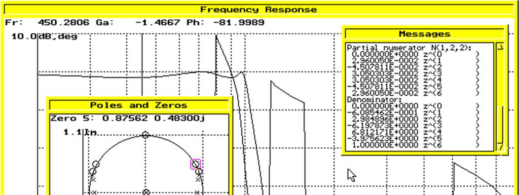
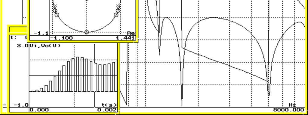
41
42 Other analysis algorithms/programs applied to S circuits The WATSNAP program, developed at the University of Waterloo, can analyze S circuits in small-signal operation, treating them as linear periodically switched linear circuits, computing: Frequency response Transient response Natural frequencies Sensitivities The algorithm used takes into account effects of incomplete stabilization. Some other programs developed for the analysis of non-ideal switched-capacitor circuits can also be used in the analysis of S circuits, and compute other characteristics, as for example, noise (SAP), or approximate transfer functions in z-transform obtained by oversampling the continuous-time frequency responses obtained lassical time-domain simulation (SPE) can be used for the analysis of nonlinear effects, provided that the transistor models are accurate, inclusive in the modeling of non-linear capacitances. ast update: 0/8/0
Chapter 13: Introduction to Switched- Capacitor Circuits
 Chapter 13: Introduction to Switched- Capacitor Circuits 13.1 General Considerations 13.2 Sampling Switches 13.3 Switched-Capacitor Amplifiers 13.4 Switched-Capacitor Integrator 13.5 Switched-Capacitor
Advanced Operational Amplifiers
 IsLab Analog Integrated Circuit Design OPA2-47 Advanced Operational Amplifiers כ Kyungpook National University IsLab Analog Integrated Circuit Design OPA2-1 Advanced Current Mirrors and Opamps Two-stage
System on a Chip. Prof. Dr. Michael Kraft
 System on a Chip Prof. Dr. Michael Kraft Lecture 4: Filters Filters General Theory Continuous Time Filters Background Filters are used to separate signals in the frequency domain, e.g. remove noise, tune
ECEN 474/704 Lab 5: Frequency Response of Inverting Amplifiers
 ECEN 474/704 Lab 5: Frequency Response of Inverting Amplifiers Objective Design, simulate and layout various inverting amplifiers. Introduction Inverting amplifiers are fundamental building blocks of electronic
SWITCHED-CURRENTS an analogue technique for digital technology
 SWITCHED-CURRENTS an analogue technique for digital technology Edited by С Toumazou, ]. B. Hughes & N. C. Battersby Supported by the IEEE Circuits and Systems Society Technical Committee on Analog Signal
Lecture 030 ECE4430 Review III (1/9/04) Page 030-1
 Page 030-1") Lecture 030 ECE4430 Review III (1/9/04) Page 0301 LECTURE 030 ECE 4430 REVIEW III (READING: GHLM Chaps. 3 and 4) Objective The objective of this presentation is: 1.) Identify the prerequisite material
Lecture 030 ECE4430 Review III (1/9/04) Page 0301 LECTURE 030 ECE 4430 REVIEW III (READING: GHLM Chaps. 3 and 4) Objective The objective of this presentation is: 1.) Identify the prerequisite material
LECTURE 19 DIFFERENTIAL AMPLIFIER
 Lecture 19 Differential Amplifier (6/4/14) Page 191 LECTURE 19 DIFFERENTIAL AMPLIFIER LECTURE ORGANIZATION Outline Characterization of a differential amplifier Differential amplifier with a current mirror
EECS3611 Analog Integrated Circuit Design. Lecture 3. Current Source and Current Mirror
 EECS3611 Analog ntegrated Circuit Design Lecture 3 Current Source and Current Mirror ntroduction Before any device can be used in any application, it has to be properly biased so that small signal AC parameters
Gechstudentszone.wordpress.com
 UNIT 4: Small Signal Analysis of Amplifiers 4.1 Basic FET Amplifiers In the last chapter, we described the operation of the FET, in particular the MOSFET, and analyzed and designed the dc response of circuits
ECEN 474/704 Lab 7: Operational Transconductance Amplifiers
 ECEN 474/704 Lab 7: Operational Transconductance Amplifiers Objective Design, simulate and layout an operational transconductance amplifier. Introduction The operational transconductance amplifier (OTA)
EE 508 Lecture 28. Integrator Design. Alaising in SC Circuits Elimination of redundant switches Switched Resistor Integrators
 EE 508 Lecture 28 Integrator Design Alaising in S ircuits Elimination of redundant switches Switched Resistor Integrators Review from last time The S integrator 1 1 I 0eq= f LK Observe this circuit has
INF4420 Switched capacitor circuits Outline
 INF4420 Switched capacitor circuits Spring 2012 1 / 54 Outline Switched capacitor introduction MOSFET as an analog switch z-transform Switched capacitor integrators 2 / 54 Introduction Discrete time analog
Prof. Paolo Colantonio a.a
 Prof. Paolo Colantonio a.a. 20 2 Field effect transistors (FETs) are probably the simplest form of transistor, widely used in both analogue and digital applications They are characterised by a very high
Operational Amplifier as A Black Box
 Chapter 8 Operational Amplifier as A Black Box 8. General Considerations 8.2 Op-Amp-Based Circuits 8.3 Nonlinear Functions 8.4 Op-Amp Nonidealities 8.5 Design Examples Chapter Outline CH8 Operational Amplifier
CHAPTER 8 DIFFERENTIAL AND MULTISTAGE AMPLIFIERS
 CHAPTER 8 DIFFERENTIAL AND MULTISTAGE AMPLIFIERS Chapter Outline 8.1 The CMOS Differential Pair 8. Small-Signal Operations of the MOS Differential Pair 8.3 The BJT Differential Pair 8.4 Other Non-ideal
INF4420. Switched capacitor circuits. Spring Jørgen Andreas Michaelsen
 INF4420 Switched capacitor circuits Spring 2012 Jørgen Andreas Michaelsen (jorgenam@ifi.uio.no) Outline Switched capacitor introduction MOSFET as an analog switch z-transform Switched capacitor integrators
Active Filter Design Techniques
 Active Filter Design Techniques 16.1 Introduction What is a filter? A filter is a device that passes electric signals at certain frequencies or frequency ranges while preventing the passage of others.
Chapter 4: Differential Amplifiers
 Chapter 4: Differential Amplifiers 4.1 Single-Ended and Differential Operation 4.2 Basic Differential Pair 4.3 Common-Mode Response 4.4 Differential Pair with MOS Loads 4.5 Gilbert Cell Single-Ended and
Chapter 13 Oscillators and Data Converters
 Chapter 13 Oscillators and Data Converters 13.1 General Considerations 13.2 Ring Oscillators 13.3 LC Oscillators 13.4 Phase Shift Oscillator 13.5 Wien-Bridge Oscillator 13.6 Crystal Oscillators 13.7 Chapter
Continuous- Time Active Filter Design
 Continuous- Time Active Filter Design T. Deliyannis Yichuang Sun J.K. Fidler CRC Press Boca Raton London New York Washington, D.C. Contents Chapter 1 Filter Fundamentals 1.1 Introduction 1 1.2 Filter Characterization
Electronic Circuits EE359A
 Electronic Circuits EE359A Bruce McNair B206 bmcnair@stevens.edu 201-216-5549 1 Memory and Advanced Digital Circuits - 2 Chapter 11 2 Figure 11.1 (a) Basic latch. (b) The latch with the feedback loop opened.
Chapter 12 Opertational Amplifier Circuits
 1 Chapter 12 Opertational Amplifier Circuits Learning Objectives 1) The design and analysis of the two basic CMOS op-amp architectures: the two-stage circuit and the single-stage, folded cascode circuit.
CHAPTER 3. Instrumentation Amplifier (IA) Background. 3.1 Introduction. 3.2 Instrumentation Amplifier Architecture and Configurations
 Background. 3.1 Introduction. 3.2 Instrumentation Amplifier Architecture and Configurations") CHAPTER 3 Instrumentation Amplifier (IA) Background 3.1 Introduction The IAs are key circuits in many sensor readout systems where, there is a need to amplify small differential signals in the presence
CHAPTER 3 Instrumentation Amplifier (IA) Background 3.1 Introduction The IAs are key circuits in many sensor readout systems where, there is a need to amplify small differential signals in the presence
ANALYSIS AND DESIGN OF ANALOG INTEGRATED CIRCUITS
 ANALYSIS AND DESIGN OF ANALOG INTEGRATED CIRCUITS Fourth Edition PAUL R. GRAY University of California, Berkeley PAUL J. HURST University of California, Davis STEPHEN H. LEWIS University of California,
ANALYSIS AND DESIGN OF ANALOG INTEGRATED CIRCUITS
 ANALYSIS AND DESIGN OF ANALOG INTEGRATED CIRCUITS Fourth Edition PAUL R. GRAY University of California, Berkeley PAUL J. HURST University of California, Davis STEPHEN H. LEWIS University of California,
Radivoje Đurić, 2015, Analogna Integrisana Kola 1
 Low power OTA 1 Two-Stage, Miller Op Amp Operating in Weak Inversion Low frequency response: gm1 gm6 Av 0 g g g g A v 0 ds2 ds4 ds6 ds7 I D m, ds D nvt g g I n GB and SR: GB 1 1 n 1 2 4 6 6 7 g 2 2 m1
Radivoje Đurić, 2015, Analogna Integrisana Kola 1
 OTA-output buffer 1 According to the types of loads, the driving capability of the output stages differs. For switched capacitor circuits which have high impedance capacitive loads, class A output stage
Yet, many signal processing systems require both digital and analog circuits. To enable
 Introduction Field-Programmable Gate Arrays (FPGAs) have been a superb solution for rapid and reliable prototyping of digital logic systems at low cost for more than twenty years. Yet, many signal processing
Basic Circuits. Current Mirror, Gain stage, Source Follower, Cascode, Differential Pair,
 Basic Circuits Current Mirror, Gain stage, Source Follower, Cascode, Differential Pair, CCS - Basic Circuits P. Fischer, ZITI, Uni Heidelberg, Seite 1 Reminder: Effect of Transistor Sizes Very crude classification:
Appendix. RF Transient Simulator. Page 1
 Appendix RF Transient Simulator Page 1 RF Transient/Convolution Simulation This simulator can be used to solve problems associated with circuit simulation, when the signal and waveforms involved are modulated
Design of Reconfigurable Baseband Filter. Xin Jin
 Design of Reconfigurable Baseband Filter by Xin Jin A thesis submitted to the Graduate Faculty of Auburn University in partial fulfillment of the requirements for the Degree of Master of Science Auburn,
TWO AND ONE STAGES OTA
 TWO AND ONE STAGES OTA F. Maloberti Department of Electronics Integrated Microsystem Group University of Pavia, 7100 Pavia, Italy franco@ele.unipv.it tel. +39-38-50505; fax. +39-038-505677 474 EE Department
Programmable analog compandor
 DESCRIPTION The NE572 is a dual-channel, high-performance gain control circuit in which either channel may be used for dynamic range compression or expansion. Each channel has a full-wave rectifier to
Chapter 2. Operational Amplifiers
 Chapter 2. Operational Amplifiers Tong In Oh 1 2.5 Integrators and Differentiators Utilized resistors in the op-amp feedback and feed-in path Ideally independent of frequency Use of capacitors together
Index. Small-Signal Models, 14 saturation current, 3, 5 Transistor Cutoff Frequency, 18 transconductance, 16, 22 transit time, 10
 Index A absolute value, 308 additional pole, 271 analog multiplier, 190 B BiCMOS,107 Bode plot, 266 base-emitter voltage, 16, 50 base-emitter voltages, 296 bias current, 111, 124, 133, 137, 166, 185 bipolar
INF3410 Fall Book Chapter 6: Basic Opamp Design and Compensation
 INF3410 Fall 2013 Compensation content Introduction Two Stage Opamps Compensation Slew Rate Systematic Offset Advanced Current Mirrors Operational Transconductance Amplifiers Current Mirror Opamps Folded
Tuesday, March 22nd, 9:15 11:00
 Nonlinearity it and mismatch Tuesday, March 22nd, 9:15 11:00 Snorre Aunet (sa@ifi.uio.no) Nanoelectronics group Department of Informatics University of Oslo Last time and today, Tuesday 22nd of March:
ETIN25 Analogue IC Design. Laboratory Manual Lab 2
 Department of Electrical and Information Technology LTH ETIN25 Analogue IC Design Laboratory Manual Lab 2 Jonas Lindstrand Martin Liliebladh Markus Törmänen September 2011 Laboratory 2: Design and Simulation
EE301 Electronics I , Fall
 EE301 Electronics I 2018-2019, Fall 1. Introduction to Microelectronics (1 Week/3 Hrs.) Introduction, Historical Background, Basic Consepts 2. Rewiev of Semiconductors (1 Week/3 Hrs.) Semiconductor materials
Chapter 4 Single-stage MOS amplifiers
 Chapter 4 Single-stage MOS amplifiers ELEC-H402/CH4: Single-stage MOS amplifiers 1 Single-stage MOS amplifiers NMOS as an amplifier: example of common-source circuit NMOS amplifier example Introduction
ECEN 474/704 Lab 8: Two-Stage Miller Operational Amplifier
 ECEN 474/704 Lab 8: Two-Stage Miller Operational Amplifier Objective Design, simulate and test a two-stage operational amplifier Introduction Operational amplifiers (opamp) are essential components of
2. Single Stage OpAmps
 /74 2. Single Stage OpAmps Francesc Serra Graells francesc.serra.graells@uab.cat Departament de Microelectrònica i Sistemes Electrònics Universitat Autònoma de Barcelona paco.serra@imb-cnm.csic.es Integrated
INTEGRATED CIRCUITS. AN179 Circuit description of the NE Dec
 TEGRATED CIRCUITS AN79 99 Dec AN79 DESCPTION The NE564 contains the functional blocks shown in Figure. In addition to the normal PLL functions of phase comparator, CO, amplifier and low-pass filter, the
Single-Stage Integrated- Circuit Amplifiers
 Single-Stage Integrated- Circuit Amplifiers Outline Comparison between the MOS and the BJT From discrete circuit to integrated circuit - Philosophy, Biasing, etc. Frequency response The Common-Source and
Karadeniz Technical University Department of Electrical and Electronics Engineering Trabzon, Turkey
 Karadeniz Technical University Department of Electrical and Electronics Engineering 61080 Trabzon, Turkey Chapter 3-2- 1 Modelling and Representation of Physical Systems 3.1. Electrical Systems Bu ders
Chapter 5. Operational Amplifiers and Source Followers. 5.1 Operational Amplifier
 Chapter 5 Operational Amplifiers and Source Followers 5.1 Operational Amplifier In single ended operation the output is measured with respect to a fixed potential, usually ground, whereas in double-ended
Design of Pipeline Analog to Digital Converter
 Design of Pipeline Analog to Digital Converter Vivek Tripathi, Chandrajit Debnath, Rakesh Malik STMicroelectronics The pipeline analog-to-digital converter (ADC) architecture is the most popular topology
A Wide Tuning Range Gm-C Continuous-Time Analog Filter
 A Wide Tuning Range Gm-C Continuous-Time Analog Filter Prashanth Kannepally Dept. of Electronics and Communication Engineering SNIST Hyderabad, India 685project6801@gmail.com Abstract A Wide Tuning Range
C H A P T E R 5. Amplifier Design
 C H A P T E 5 Amplifier Design The Common-Source Amplifier v 0 = r ( g mvgs )( D 0 ) A v0 = g m r ( D 0 ) Performing the analysis directly on the circuit diagram with the MOSFET model used implicitly.
ETI , Good luck! Written Exam Integrated Radio Electronics. Lund University Dept. of Electroscience
 und University Dept. of Electroscience EI170 Written Exam Integrated adio Electronics 2010-03-10, 08.00-13.00 he exam consists of 5 problems which can give a maximum of 6 points each. he total maximum
Applied Electronics II
 Applied Electronics II Chapter 3: Operational Amplifier Part 1- Op Amp Basics School of Electrical and Computer Engineering Addis Ababa Institute of Technology Addis Ababa University Daniel D./Getachew
Switched Mode Power Conversion Prof. L. Umanand Department of Electronics Systems Engineering Indian Institute of Science, Bangalore
 Switched Mode Power Conversion Prof. L. Umanand Department of Electronics Systems Engineering Indian Institute of Science, Bangalore Lecture -1 Introduction to DC-DC converter Good day to all of you, we
Operational Amplifiers
 CHAPTER 9 Operational Amplifiers Analog IC Analysis and Design 9- Chih-Cheng Hsieh Outline. General Consideration. One-Stage Op Amps / Two-Stage Op Amps 3. Gain Boosting 4. Common-Mode Feedback 5. Input
CMOS Operational-Amplifier
 CMOS Operational-Amplifier 1 What will we learn in this course How to design a good OP Amp. Basic building blocks Biasing and Loading Swings and Bandwidth CH2(8) Operational Amplifier as A Black Box Copyright
Transistor Characterization
 1 Transistor Characterization Figure 1.1: ADS Schematic of Transistor Characterization Circuit 1.1 Question 1 The bias voltage, width, and length of a single NMOS transistor (pictured in Figure 1.1) were
Chapter 2 MODELING AND CONTROL OF PEBB BASED SYSTEMS
 Chapter 2 MODELING AND CONTROL OF PEBB BASED SYSTEMS 2.1 Introduction The PEBBs are fundamental building cells, integrating state-of-the-art techniques for large scale power electronics systems. Conventional
Solid State Devices & Circuits. 18. Advanced Techniques
 ECE 442 Solid State Devices & Circuits 18. Advanced Techniques Jose E. Schutt-Aine Electrical l&c Computer Engineering i University of Illinois jschutt@emlab.uiuc.edu 1 Darlington Configuration - Popular
FOR applications such as implantable cardiac pacemakers,
 1576 IEEE JOURNAL OF SOLID-STATE CIRCUITS, VOL. 32, NO. 10, OCTOBER 1997 Low-Power MOS Integrated Filter with Transconductors with Spoilt Current Sources M. van de Gevel, J. C. Kuenen, J. Davidse, and
CHAPTER 4 ULTRA WIDE BAND LOW NOISE AMPLIFIER DESIGN
 93 CHAPTER 4 ULTRA WIDE BAND LOW NOISE AMPLIFIER DESIGN 4.1 INTRODUCTION Ultra Wide Band (UWB) system is capable of transmitting data over a wide spectrum of frequency bands with low power and high data
EE 435 Switched Capacitor Amplifiers and Filters. Lab 7 Spring 2014 R 2 V OUT V IN. (a) (b)
 (b)") EE 435 Switched Capacitor Amplifiers and Filters Lab 7 Spring 2014 Amplifiers are widely used in many analog and mixed-signal applications. In most discrete applications resistors are used to form the
EE 435 Switched Capacitor Amplifiers and Filters Lab 7 Spring 2014 Amplifiers are widely used in many analog and mixed-signal applications. In most discrete applications resistors are used to form the
Integrated Circuit Design for High-Speed Frequency Synthesis
 Integrated Circuit Design for High-Speed Frequency Synthesis John Rogers Calvin Plett Foster Dai ARTECH H O US E BOSTON LONDON artechhouse.com Preface XI CHAPTER 1 Introduction 1 1.1 Introduction to Frequency
Applied Electronics II
 Applied Electronics II Chapter 2: Differential Amplifier School of Electrical and Computer Engineering Addis Ababa Institute of Technology Addis Ababa University Daniel D./Abel G. April 4, 2016 Chapter
SWITCHED CAPACITOR CIRCUITS
 EE37 Advanced Analog ircuits Lecture 7 SWITHED APAITOR IRUITS Richard Schreier richard.schreier@analog.com Trevor aldwell trevor.caldwell@utoronto.ca ourse Goals Deepen Understanding of MOS analog circuit
Basic distortion definitions
 Conclusions The push-pull second-generation current-conveyor realised with a complementary bipolar integration technology is probably the most appropriate choice as a building block for low-distortion
INTRODUCTION TO ELECTRONICS EHB 222E
 INTRODUCTION TO ELECTRONICS EHB 222E MOS Field Effect Transistors (MOSFETS II) MOSFETS 1/ INTRODUCTION TO ELECTRONICS 1 MOSFETS Amplifiers Cut off when v GS < V t v DS decreases starting point A, once
Chapter 9: Operational Amplifiers
 Chapter 9: Operational Amplifiers The Operational Amplifier (or op-amp) is the ideal, simple amplifier. It is an integrated circuit (IC). An IC contains many discrete components (resistors, capacitors,
For the purpose of this problem sheet use the model given in the lecture notes.
 Analogue Electronics Questions Todd Huffman & Tony Weidberg, MT 2018 (updated 30/10/18). For the purpose of this problem sheet use the model given in the lecture notes. The current gain is defined by a
UNIT I. Operational Amplifiers
 UNIT I Operational Amplifiers Operational Amplifier: The operational amplifier is a direct-coupled high gain amplifier. It is a versatile multi-terminal device that can be used to amplify dc as well as
EE 435. Lecture 10: Folded-Cascode Amplifiers Current Mirror Op Amps
 EE 435 ecture 0: Folded-ascode mplifiers urrent Mirror Op mps Where we are at: Basic Op mp Desin Fundamental mplifier Desin Issues Sinle-Stae ow Gain Op mps Sinle-Stae Hih Gain Op mps Other Basic Gain
A 16Ω Audio Amplifier with 93.8 mw Peak loadpower and 1.43 quiscent power consumption
 A 16Ω Audio Amplifier with 93.8 mw Peak loadpower and 1.43 quiscent power consumption IEEE Transactions on circuits and systems- Vol 59 No:3 March 2012 Abstract A class AB audio amplifier is used to drive
4.5 Biasing in MOS Amplifier Circuits
 4.5 Biasing in MOS Amplifier Circuits Biasing: establishing an appropriate DC operating point for the MOSFET - A fundamental step in the design of a MOSFET amplifier circuit An appropriate DC operating
Microelectronic Circuits II. Ch 10 : Operational-Amplifier Circuits
 Microelectronic Circuits II Ch 0 : Operational-Amplifier Circuits 0. The Two-stage CMOS Op Amp 0.2 The Folded-Cascode CMOS Op Amp CNU EE 0.- Operational-Amplifier Introduction - Analog ICs : operational
INF3410 Fall Book Chapter 6: Basic Opamp Design and Compensation
 INF3410 Fall 2015 Book Chapter 6: Basic Opamp Design and Compensation content Introduction Two Stage Opamps Compensation Slew Rate Systematic Offset Advanced Current Mirrors Operational Transconductance
MAS.836 HOW TO BIAS AN OP-AMP
 MAS.836 HOW TO BIAS AN OP-AMP Op-Amp Circuits: Bias, in an electronic circuit, describes the steady state operating characteristics with no signal being applied. In an op-amp circuit, the operating characteristic
F9 Differential and Multistage Amplifiers
 Lars Ohlsson 018-10-0 F9 Differential and Multistage Amplifiers Outline MOS differential pair Common mode signal operation Differential mode signal operation Large signal operation Small signal operation
ELECTRICAL CIRCUITS 6. OPERATIONAL AMPLIFIERS PART III DYNAMIC RESPONSE
 77 ELECTRICAL CIRCUITS 6. PERATAL AMPLIIERS PART III DYNAMIC RESPNSE Introduction In the first 2 handouts on op-amps the focus was on DC for the ideal and non-ideal opamp. The perfect op-amp assumptions
Switch Mode Power Conversion Prof. L. Umanand Department of Electronics System Engineering Indian Institute of Science, Bangalore
 Switch Mode Power Conversion Prof. L. Umanand Department of Electronics System Engineering Indian Institute of Science, Bangalore Lecture - 30 Implementation on PID controller Good day to all of you. We
Analysis and Design of Analog Integrated Circuits Lecture 8. Cascode Techniques
 Analysis and Design of Analog Integrated Circuits Lecture 8 Cascode Techniques Michael H. Perrott February 15, 2012 Copyright 2012 by Michael H. Perrott All rights reserved. Review of Large Signal Analysis
CMOS Circuit for Low Photocurrent Measurements
 CMOS Circuit for Low Photocurrent Measurements W. Guggenbühl, T. Loeliger, M. Uster, and F. Grogg Electronics Laboratory Swiss Federal Institute of Technology Zurich, Switzerland A CMOS amplifier / analog-to-digital
ECE626 Project Switched Capacitor Filter Design
 ECE626 Project Switched Capacitor Filter Design Hari Prasath Venkatram Contents I Introduction 2 II Choice of Topology 2 III Poles and Zeros 2 III-ABilinear Transform......................................
Lecture 3 Switched-Capacitor Circuits Trevor Caldwell
 Advanced Analog Circuits Lecture 3 Switched-Capacitor Circuits Trevor Caldwell trevor.caldwell@analog.com Lecture Plan Date Lecture (Wednesday 2-4pm) Reference Homework 2017-01-11 1 MOD1 & MOD2 ST 2, 3,
Integrated Circuit: Classification:
 Integrated Circuit: It is a miniature, low cost electronic circuit consisting of active and passive components that are irreparably joined together on a single crystal chip of silicon. Classification:
444 Index. F Fermi potential, 146 FGMOS transistor, 20 23, 57, 83, 84, 98, 205, 208, 213, 215, 216, 241, 242, 251, 280, 311, 318, 332, 354, 407
 Index A Accuracy active resistor structures, 46, 323, 328, 329, 341, 344, 360 computational circuits, 171 differential amplifiers, 30, 31 exponential circuits, 285, 291, 292 multifunctional structures,
Experiment #7 MOSFET Dynamic Circuits II
 Experiment #7 MOSFET Dynamic Circuits II Jonathan Roderick Introduction The previous experiment introduced the canonic cells for MOSFETs. The small signal model was presented and was used to discuss the
F7 Transistor Amplifiers
 Lars Ohlsson 2018-09-25 F7 Transistor Amplifiers Outline Transfer characteristics Small signal operation and models Basic configurations Common source (CS) CS/CE w/ source/ emitter degeneration resistance
Analysis and Design of Autonomous Microwave Circuits
 Analysis and Design of Autonomous Microwave Circuits ALMUDENA SUAREZ IEEE PRESS WILEY A JOHN WILEY & SONS, INC., PUBLICATION Contents Preface xiii 1 Oscillator Dynamics 1 1.1 Introduction 1 1.2 Operational
Modulator with Op- Amp Gain Compensation for Nanometer CMOS Technologies
 A. Pena Perez, V.R. Gonzalez- Diaz, and F. Maloberti, ΣΔ Modulator with Op- Amp Gain Compensation for Nanometer CMOS Technologies, IEEE Proceeding of Latin American Symposium on Circuits and Systems, Feb.
Lecture 17: BJT/FET Mixers/Mixer Noise
 EECS 142 Lecture 17: BJT/FET Mixers/Mixer Noise Prof. Ali M. Niknejad University of California, Berkeley Copyright c 2005 by Ali M. Niknejad A. M. Niknejad University of California, Berkeley EECS 142 Lecture
Lecture 20: Passive Mixers
 EECS 142 Lecture 20: Passive Mixers Prof. Ali M. Niknejad University of California, Berkeley Copyright c 2005 by Ali M. Niknejad A. M. Niknejad University of California, Berkeley EECS 142 Lecture 20 p.
Oscillators. An oscillator may be described as a source of alternating voltage. It is different than amplifier.
 Oscillators An oscillator may be described as a source of alternating voltage. It is different than amplifier. An amplifier delivers an output signal whose waveform corresponds to the input signal but
CMOS Operational-Amplifier
 CMOS Operational-Amplifier 1 What will we learn in this course How to design a good OP Amp. Basic building blocks Biasing and Loading Swings and Bandwidth CH2(8) Operational Amplifier as A Black Box Copyright
Difference between BJTs and FETs. Junction Field Effect Transistors (JFET)
") Difference between BJTs and FETs Transistors can be categorized according to their structure, and two of the more commonly known transistor structures, are the BJT and FET. The comparison between BJTs
Difference between BJTs and FETs Transistors can be categorized according to their structure, and two of the more commonly known transistor structures, are the BJT and FET. The comparison between BJTs
Chapter 4. CMOS Cascode Amplifiers. 4.1 Introduction. 4.2 CMOS Cascode Amplifiers
 Chapter 4 CMOS Cascode Amplifiers 4.1 Introduction A single stage CMOS amplifier cannot give desired dc voltage gain, output resistance and transconductance. The voltage gain can be made to attain higher
ECEN620: Network Theory Broadband Circuit Design Fall 2012
 ECEN620: Network Theory Broadband Circuit Design Fall 2012 Lecture 11: Charge Pump Circuits Sam Palermo Analog & Mixed-Signal Center Texas A&M University Announcements & Agenda Exam 1 is on Wed. Oct 3
Practical Testing Techniques For Modern Control Loops
 VENABLE TECHNICAL PAPER # 16 Practical Testing Techniques For Modern Control Loops Abstract: New power supply designs are becoming harder to measure for gain margin and phase margin. This measurement is
Experiment 1: Amplifier Characterization Spring 2019
 Experiment 1: Amplifier Characterization Spring 2019 Objective: The objective of this experiment is to develop methods for characterizing key properties of operational amplifiers Note: We will be using
MOSFET in ON State (V GS > V TH )
") ndian nstitute of Technology Jodhpur, Year 08 Analog Electronics (ourse ode: EE34) ecture 8 9: MOSFETs, Biasing ourse nstructor: Shree Prakash Tiwari Email: sptiwari@iitj.ac.in Webpage: http://home.iitj.ac.in/~sptiwari/
ndian nstitute of Technology Jodhpur, Year 08 Analog Electronics (ourse ode: EE34) ecture 8 9: MOSFETs, Biasing ourse nstructor: Shree Prakash Tiwari Email: sptiwari@iitj.ac.in Webpage: http://home.iitj.ac.in/~sptiwari/
A new class AB folded-cascode operational amplifier
 A new class AB folded-cascode operational amplifier Mohammad Yavari a) Integrated Circuits Design Laboratory, Department of Electrical Engineering, Amirkabir University of Technology, Tehran, Iran a) myavari@aut.ac.ir
Orister Corporation. LDO Thesis
 Orister Corporation LDO Thesis AGENDA What is a Linear egulator LDO ntroductions LDO S Terms and Definitions LDO S LAYOUT What s a Linear egulator A linear regulator operates by using a voltage-controlled
(W) 2003 Analog Integrated Electronics Assignment #2
 2003 Analog Integrated Electronics Assignment #2") 97.477 (W) 2003 Analog Integrated Electronics Assignment #2 written by Leonard MacEachern, Ph.D. c 2003 by Leonard MacEachern. All Rights Reserved. 1 Assignment Guidelines The purpose of this assignment
97.477 (W) 2003 Analog Integrated Electronics Assignment #2 written by Leonard MacEachern, Ph.D. c 2003 by Leonard MacEachern. All Rights Reserved. 1 Assignment Guidelines The purpose of this assignment