Karadeniz Technical University Department of Electrical and Electronics Engineering Trabzon, Turkey
|
|
|
- Mary Floyd
- 6 years ago
- Views:
Transcription

1 Karadeniz Technical University Department of Electrical and Electronics Engineering Trabzon, Turkey Chapter Modelling and Representation of Physical Systems 3.1. Electrical Systems Bu ders notları sadece bu dersi alan öğrencilerin kullanımına açık olup, üçüncü sahıslara verilmesi, herhangi bir yöntemle çoğaltılıp başka yerlerde kullanılması, yayınlanması Prof. Dr. İsmail H. ALTAŞ ın yazılı iznine tabidir. Aksi durumlarda yasal işlem yapılacaktır. Chapter
2 Model representation Integro-differential equations Simulation diagrams (detailed models) Block diagrams (Combined models) Signal flow graghs State-Space equations Transfer functions Chapter Model representation input cause block system BLOCK DIAGRAM output effect It helps in the realization, synthesis or fabrication of systems A simulation of the system may be realized from the block diagram by interconnecting the basic building blocks. It helps in the analysis and the design of systems as it provides a clear picture of the cause and effect relationship governing the various signals within the system. v Operation and analysis in time domain v Operation and analysis in frequency domain Chapter


3 Model representation BLOCK DIAGRAM Laplace transform or Fourier transform or z- transform Transfer Function is a mathematical operator that relates the input and the output. A system element represented by a block may be either a static element or a dynamic element: Chapter Electrical Component Models i i v _ v _ voltage/current voltage/charge Inductance v = L di/dt v = L dq 2 /dt 2 Resistance v = R i v = R dq/dt i v _ Capacitance v = 1/C ò i dt v = 1/C q Chapter
4 Model representation u a y BLOCK DIAGRAM Linear gain u y u Integral gain f(u) Nonlinear gain y Chapter Operation and analysis in time domain Model representation BLOCK DIAGRAM The input and the outputs are functions of time u=sin(t) y y y u u u Integral gain t Linear gain y=au y=3u Nonlinear gain F=f(u) y = u 3u 3 y = u 2 y=sin(u) Chapter


5 The integration notation Model representation BLOCK DIAGRAM Initial condition, y(0) integration terms Chapter Model representation BLOCK DIAGRAM The integration notation Integrator Integrator An integrator block with an indefinite integral sign is equivalent to a definite integrator block and a summer Chapter
6 Model representation Static element NO MEMORY BLOCK DIAGRAM y = 3u, y = u, y=sin(u) 3 The output at the instant t 1 depands on the input at the same instant t 1. Chapter Model representation Static element t(s) E (V) u R (V) t1 E1 U R 1 t2 E2 U R 2 t3 E3 U R 3 t4 E4 U R 4 BLOCK DIAGRAM NO MEMORY U R (V) u R (V) E(V) t (s) Chapter
7 Model representation Potentiometer Static element Obtain the block representation of a potentiometer shown below Chapter Potentiometer Static element case 1: microscopic picture: a detailed block diagram representation. step 1: identify the input and the output : Model representation step 2: usually input is located on the left and output to the right step 3: relate v i to v o using internal variables. v i is input, v o is output and i is an internal variable. Chapter


8 Model representation Potentiometer Summing Rectangular Blocks Take off point Detailed Block Representation Chapter Model representation Potentiometer Chapter

9 case 2: Model representation Potentiometer macroscopic picture: a single block representation relating merely the input and the output The block diagram is thus an interconnection of : a.rectangular gain blocks b.summing junctions and c.takeoff points Chapter Model representation Dynamic element HAS MEMORY Chapter

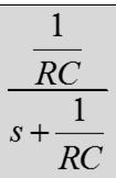
10 Model representation Dynamic element HAS MEMORY This is called a low-pass filter. Chapter Model representation Dynamic element HAS MEMORY Chapter

 - A")
11 Model representation Dynamic element X low-pass filter. seconds t(s) Chapter Model representation Dynamic element t(s) - A low-pass filter. Chapter


12 Model representation Dynamic element Solution: This is called a low-pass filter. Simulate in Matlab/Simulink using the numerical data given as; C=1 µf, R=10 kw; V=10 V Chapter Model representation Dynamic element HAS MEMORY (0) Chapter


13 Model representation Dynamic element HAS MEMORY Chapter Model representation Dynamic element X Step input t(s) Chapter
14 Model representation HAS MEMORY Dynamic element - t(s) Chapter Model representation Dynamic element HAS MEMORY Simulate in Matlab/Simulink using the numerical data given as; L=200 mh, R=10 kw; V=10 V - Chapter
15 Model representation Obtain a block diagram of the following system described by an integral equation. where u is the input and y is the output. t(s) Initial conditions are zero, u C (0)=0. Chapter Model representation EXAMPLES step 1: usually input is located on the left and output to the right step 2: Rewrite the integral equation with the highest orfer term on the left hand side and the rest on the right hand side Chapter
16 Model representation EXAMPLES OR step 3: treat the term, inputs are u(t) and as an output of a summer whose step 4: generate from the output of the summer, y(t) and the terms Chapter Model representation EXAMPLES step 5: interconnect the blocks summer For capacitor circuit - pick-off REPLACE: blocks Chapter

17 Model representation EXAMPLES Block diagram should not contain differentiator elements. Only integrators should be present. To avoid using differentiators, use integrators to generate various derivatives. Here we need to generate the 3 derivative of y, which is generated as follows: Starting from the highest order (third order) derivative generate the lower order derivatives (second, first and zero order) by cascading integrators. Chapter Model representation EXAMPLES Obtain the block diagram representation of the following integro-differential equation Chapter
18 Model representation EXAMPLES step 1: express the equation with the term representing the highest order derivative of the output on the left hand side and the rest of the terms on the right hand side step 2: treat the highest order term as an output of a summer with rest of the terms as inputs Chapter Step 4: interconnect the blocks Model representation EXAMPLES step 3: from the highest order term, generate the terms and - - Chapter


19 Model representation State-Space Model State-Space Model Chapter Model representation State-Space Model State vector State variables A: System matrix B: Input matrix C: Output matrix Output variable State-Space Model Chapter

20 Model representation Select Kp=20 and Ki=50 to simulate with a PI controller. L=2 H, R=10 Ohm; C=100 F V=50 V Chapter Obtain the block diagram for a spacecraft platform : Solution 6 Chapter
21 Solution 6 Chapter Operational amplifiers Chapter


22 Operational amplifiers This image is taken from the internet Chapter Operational amplifiers The operational amplifiers are used to build analog circuits. OP-AMPs are the key elements used in realization of analog controllers. They are used as: v GAIN: multiplication of a signal by a constant for amplification or attenuation v SUMMER: addition of two or more signals v INTEGRATOR: integration of a signal Chapter
23 Inverting operational amplifier circuits inverting configuration Inversion Choose Z f =Z i u -u -1 Chapter Inverting operational amplifier circuits Addition: n signals (v i, i=1,2,3,..., n) are added to give an output v 0 Chapter
24 Inverting operational amplifier circuits Addition: -1 Chapter Inverting operational amplifier circuits Multiplication Multiplying by a constant: Choose Z f =R f and Z i =R i ; that is connected resistors in the feedback path and at the input: Chapter
25 Inverting operational amplifier circuits Multiplication Proportional Control -1 Chapter Inverting operational amplifier circuits Integration Choose: and That is connect a capacitor in the feedback path and a resistor in the input path. Chapter
26 Integration Inverting operational amplifier circuits Integral Control Chapter Inverting operational amplifier circuits Derivation Choose: and That is connect a capacitor in the input path and the resistor in the feedback path. Chapter
27 Inverting operational amplifier circuits Derivation Derivative Control Chapter PID CONTROLLERS PROPORTIONAL INTEGRAL DERIVATIVE Chapter
28 CONTROLLERS Power Source R(s) E(s) Controller U(s) Actuator u x The plant Sensor Feedback Controllers Two position (on-off) controllers Proportional controllers (P) Integral controllers (I) Proportional Integral controllers (PI) Proportional Derivative controllers (PD) Proportional Integral Derivative controllers (PID) State-Feedback Controllers Lead / lag compensators Chapter CONTROLLERS PID Proportional Integral (PI) Controller Chapter
29 CONTROLLERS Proportional Derivative (PD) Controller PID Chapter CONTROLLERS Proportional Derivative (PD) Controller PID Chapter

30 CONTROLLERS PID Proportional Integral Derivative (PID) Controller Chapter Model representation ADDING A CONTROLLER TO A PHYSICAL SYSTEM Chapter
31 Model representation ADDING A CONTROLLER TO A PHYSICAL SYSTEM Chapter Model representation ADDING A CONTROLLER TO A PHYSICAL SYSTEM Chapter
32 ADDING A CONTROLLER TO A PHYSICAL SYSTEM Application of a PI controller in order to control the current i flowing through a series RLC circuit. L=2 H, R=10 Ohm; C=100 F V=50 V Select Kp=20 and Ki=50 to simulate with a PI controller. Chapter ADDING A CONTROLLER TO A PHYSICAL SYSTEM PI Controller Chapter
33 Model representation Elements of Simulation Diagrams Summer Chapter Model representation Elements of Simulation Diagrams Pick-off point pick-off point pick-off point Gain B locks a Linear gain Integral gain f(u) Nonlinear gain Chapter
34 Model representation Elements of Simulation Diagrams The block diagram is a pictorial representation of the mathematical model of the system. The block diagram is not unique. For a given system one may obtain an infinite number of block diagrams all of which characterize the same mathematical model. An elemental block diagram should not contain differentiator blocks. It may only contain Linear gain, nonlinear gain, integrator and summer blocks. Pick off points Chapter Model representation Solved Problems in time domain Chapter
35 Model representation Obtain the block diagram representation of the following differential equation step 1: express the equation with the term representing the highest order derivative of the output on the left hand side and the rest of the terms on the right hand side Chapter Model representation Chapter
36 Model representation illustrate the importance of a block diagram using the following circuits. v is input, i 2 is the output Fig. A v is input, i 2 is the output Fig. B the loop equations for the above RL circuits can be chosen in two ways as shown above. Chapter Model representation A) Consider the figure A on the left. The loop equation yields Expressing in the matrix form yields Chapter
37 Model representation The matrix is singular. Hence there is redundancy in the set of equations. Adding the equations we get The currents i 1 and i 2 lie on a plane. There is only one differential equation (and not two differential equations) governing the above system. Chapter Model representation B) Consider the figure B on the right. Using a different set of loop equations we get Now you can easily draw the block diagram. Chapter
38 Model representation Obtain the block diagram of the following circuit. Solution P3 Re-write the equations, with the highest derivative terms of the corresponding loop on the LHS. Chapter Model representation Chapter
39 Model representation NOTE In the first equation, for the loop 1 highest order derivative term and Lowest order term. In the second equation, for the loop 2 highest order derivative term and and Lowest order terms. Chapter Model representation Obtain the mathematical model and simulation diagram Solution P4 Let us use the mesh equation : Chapter
40 Model representation Step 2: Express the equations with highest order derivative to the left. Step 3: Since the left hand side of equation (1) and (2) contains more than one derivative term: we will use matrix formulation to obtain only a single derivative term in each equation. Chapter Model representation Expressing in the matrix form yields: inverting the matrix yields : Chapter
41 Model representation simplifying yields Hence simplifying we get 1 Chapter Model representation Simplifying yields Simplifying we get 2 Chapter
42 Model representation Chapter Model representation Obtain the block diagram of the following Solution P5 Chapter


43 Model representation Expressing the differential equations with the highest order derivatives to the left yields The inputs The output internal variables, Chapter Model representation Chapter
44 Obtain the block diagram representation of the following passive circuit with e i as input and e o as the output in the frequency domain. Chapter Taking the Laplace transform yields (assume zero initial condition) or and Chapter
45 Chapter Now consider the case when the initial conditions are not zero. Taking the Laplace transform yields (assume non-zero initial condition) Solution: or Chapter
46 ASIDE Chapter Chapter
47 Obtain the block diagram of the following circuit. Solution P7 Taking the Laplace transform and assuming zero initial conditions, we get Chapter This is called a high-pass filter. Chapter
48 Unsolved Examples Chapter Model representation UE 1 Obtain the simulation diagram of the following circuit in time domain. Assume that e i (t) as input and e 0 (t) as the output This is called a high pass filter Chapter
49 Model representation UE 2 Obtain the block diagram of the following RC circuit. Exercise for students Chapter Model representation UE 3 Obtain the simulation diagram of the following circuit in time domain. Assume that e i (t) as input and e 0 (t) as the output This is called a high pass filter Chapter
50 Operational amplifiers Additional study topic for the students This section will not be included in exams of this course Chapter Operational amplifiers The operational amplifiers are used to build analog circuits. OP-AMPs are the key elements used in realization of analog controllers. They are used as: v GAIN: multiplication of a signal by a constant for amplification or attenuation v SUMMER: addition of two or more signals v INTEGRATOR: integration of a signal Chapter
51 Operational amplifiers Most physical systems may be modeled using an ordinary differential equation and the ordinary differential equation can be expressed in terms of four basic operations. v addition. v inversion v gain (multiplication by a constant) v integration. Using the operational amplifiers the ordinary differential equation model can be simulated by realizing these four basic operations. When the operational amplifiers are configured to simulate a mathematical model, the operational amplifier set up is called an analog computer. Chapter Operational amplifiers The analog computers The analog computers are used to simulate a real world (continuoustime) systems. They have advantages over the digital computers: the signals need not be sampled and hence can handle very high bandwidth signals; simulation is performed in real time; hardware in the loop (the physical system is simulated on an analog computer while the control or filtering operations are performed using on a digital computer) simulations is performed to provide a physical insight to the actual operation. However in recent times as the digital computers are becoming are becoming more powerful and cheaper, and analog to digital and digital converters are becoming faster many of the continuous time simulations may be performed on a digital computers fairly accurately and in real time. Chapter
52 Operational amplifiers The further application of the operational amplifiers include v realization of a circuit with a specified transfer function: op-amplifiers serve as building blocks to realize analog circuits v realization of filters: (e.g. low-pass, high pass, band-pass and notch filters) v realization of a buffer between a high impedance source and a low impedance load. Chapter A mathematical model of the operational amplifier In practice, three different models are employed in the analysis and design of the operational amplifiers Rigorous model Approximate model Ideal model Chapter
53 A mathematical model of the operational amplifier The rigorous model 15 V Symbol -15 V Equivalent circuit Z inp is the input impedance, Z out is the output impedance, A is the amplifier gain. Chapter A mathematical model of the operational amplifier The approximate model Assuming: Z inp = and Z out =0. However, the gain A is finite as in the rigorous model Chapter
54 A mathematical model of the operational amplifier Ideal model by assuming Z inp = and Z out = 0 and A=. This implies that v1 v2=0, i inp =0. Chapter The operational amplifier circuits: Always used in closed-loop configuration to ensure: very low sensitivity to noise, variations in the supply voltage, variations in the parameters of the transistors etc., improve linearity, increase the input impedance, reduce the output impedance and increase the bandwidth. Chapter
55 The operational amplifier circuits: In the open-loop configuration the output will saturate due to ever present noise: The output v 0 will be very large even (v 1 v 2 )is negligible since A. Chapter The operational amplifier circuits: The operational amplifier circuit configurations are of two types: 1. non-inverting configuration 2. inverting configuration Non-inverting operational amplifier circuits Non-inverting configuration Voltage follower (For Zi = and Zf =0) Chapter
56 The operational amplifier circuits: The gain of the non-inverting amplifier is positive and is always greater than unity, and the input impedance is very large (» ). If we set Z i = and Z f =0 the circuit is reduced to a voltage follower (an unity gain amplifier). The voltage follower is useful as a buffer amplifier or as a impedance converter. As a buffer amplifier the voltage follower isolates one circuit from the loading effect of the following stage. Chapter The operational amplifier circuits: For example For D/A converters, a high input impedance load is required for correct operation but do not desire output voltage scaling. The load generally has low input impedance and hence a voltage follower may be used as buffer between the D/A converter and the low input impedance load. It is also useful following the hold circuit in the sample-andhold circuit to prevent capacitor discharge. Chapter
57 Inverting operational amplifier circuits: inverting configuration The inverting operational amplifier circuits are used widely to realize addition, multiplication by a constant, inversion, integration. Chapter Inverting operational amplifier circuits: Addition: n signals (v i, i=1,2,3,..., n) are added to give an output v 0 Chapter
58 Inverting operational amplifier circuits: Multiplication Multiplying by a constant: Choose Z f =R f and Z i =R i ; that is connected resistors in the feedback path and at the input: Chapter Inverting operational amplifier circuits: Inversion Choose Z f =Z i Chapter
59 Integration Choose: Inverting operational amplifier circuits: and That is connect a capacitor in the feedback path and a resistor in the input path. Chapter Inverting operational amplifier circuits: Derivation Choose: and That is connect a capacitor in the input path and the resistor in the feedback path. Chapter
60 Inverting operational amplifier circuits: The operational amplifier operates correctly (operates in the linear range) if the input voltages are constrained to some range which is determined by the power supply voltage. For the usual ±15V supply, the input voltage range is If the voltage exceeds ±13V range, then the saturation sets in and the operation amplifier circuits operate incorrectly. The input impedance of the inverting circuit is usually low when compared to the non-inverting circuit( input impedance is infinity). Since the inverting terminal is virtually grounded, the input impedance is Z i. However the output impedance is zero. Chapter inverting operational amplifier Node 1 Node 2 V E(s) - A(s)E(s) V 0 Chapter

 Z i (s) E(s) V 0 (s) Z 1 Z i Y 1 Y i Z f Y f K.C.")
61 inverting operational amplifier Node 1 V E(s) - Node 2 V 0 A(s)E(s) Kirchoff s law: node equations. Choose the nodes as node 1: junction of Z 1 and Z f node 2 : the junction of Z 0, Z f and Z L. Chapter inverting operational amplifier Consider the node 1: The expression of E(s) is obtained by considering the input circuit : V 1 (s) Z i (s) E(s) V 0 (s) Z 1 Z i Y 1 Y i Z f Y f K.C.L: 1 Chapter
 is")


62 inverting operational amplifier Consider the node 2: The expression of V 0 (s) is obtained by considering the input circuit : Z f Y f E Z 0 Z L V 0 Z 0 Z L Y 0 Y L A(s)E(s) - 2 Chapter = inverting operational amplifier 2 = Chapter

63 inverting operational amplifier The block diagram indicate that there is feedback. The feedback block can be eliminated by block reduction Chapter inverting operational amplifier Chapter


64 inverting operational amplifier - Chapter inverting operational amplifier Chapter


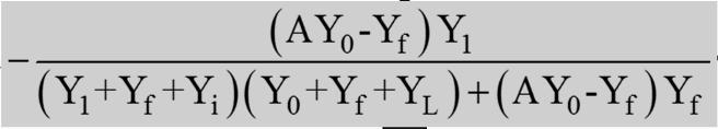
65 inverting operational amplifier Chapter inverting operational amplifier The transfer function: Chapter


66 inverting operational amplifier It is instructive to represent the block diagram with standard negative feedback system as follows: - Negative feedback Chapter inverting operational amplifier - Further simplification of the feedback loop yields feedback system as follows: case 1: the amplifier gain A is infinitely large Since A is very large AY 0 >> Y f and hence we can approximate the inverting amplifier block further. Chapter
67 inverting operational amplifier - If the output impedance Z 0 =0 that is Y 0 = then the block diagram reduces to - Chapter inverting operational amplifier Let the input impedance be infinity ( op-amp draws no current), Y i =0 and the output impedance be zero, Y 0 = but the gain A is finite as shown in the figure below. V E(s) - V 0 A(s)E(s) Then the block diagram becomes Chapter


68 inverting operational amplifier - Y i =0 Y 0 = - Chapter inverting operational amplifier Approximate model of an inverting operational amplifier V 1 e - V 0 An op-amp and its equivalent circuit is given. Obtain a block diagram. W V e - 1 Ae V 0 Chapter

69 inverting operational amplifier W V e - 1 Ae V 0 Consider the nodal equation at the junction of the three impedances: the output Chapter inverting operational amplifier Consider the output Chapter
 Chapter 3-2- 139 inverting operational")
70 inverting operational amplifier Obtain the block diagram of an operational amplifier shown below. V e - 1 Ae V 0 Assume the input impedance, Z i is infinity the output impedance, Z 0, is zero the amplifier gain, A, is finite ( the gain A is not infinity) Chapter inverting operational amplifier Consider the nodal equation at the junction of the two impedances: V e - 1 Ae V 0 the output Chapter
71 inverting operational amplifier Chapter Ideal model of an operational amplifier Ideal model of an operational amplifier will have inverting operational amplifier The amplification, A, as a constant, i.e. the gain A is independent of the frequency (the bandwidth is infinity), The gain, A is infinitely large, A The input impedance, Z i is infinitely large, Z i The output impedance, Z 0 is negligibly small, Z 0 0 In view of A, v 1 v 2» 0, v 1 and v 2 are at the same potential. If v 2 is grounded (that is v 2 =0), then v 1 is at a virtual ground ( v 1» 0). It is comforting to know that the assumption of an ideal model is valid in many application. Chapter
 2. Obtain the model directly 1.")
72 Ideal model of an operational amplifier One may obtain the model of the ideal operational amplifier circuit in two ways: 1. Derive from the non-ideal case by imposing the above 3 conditions (A, Z i and Z 0 0) 2. Obtain the model directly 1. Derivation from the non-ideal case inverting operational amplifier The conditions 2 and 3 are equivalent to Y i = 0 and Y 0 =. Since A(s)Y 0 (s) is large, dividing both numerator and denominator by A(s)Y 0 (s) and taking the limit as A(s)Y 0 (s) approaches infinity yields: Chapter Ideal model of an operational amplifier 2. Direct derivation inverting operational amplifier V 1 I=0 - E=0 V 0 Ideal operational amplifier, I=0 and E=0. Chapter

73 Ideal model of an operational amplifier inverting operational amplifier Consider the ideal operational amplifier circuit. Since the gain, A, is infinite, the voltage across i the input terminals, -, and,, namely E=0. Further since the input impedance, Z i, is infinite, the current input to the op-amp, i=0. Hence applying Kirchhoff s law and using the nodal equation we get Since E=0 we get I= V E=0 V 0 Chapter Ideal model of an operational amplifier inverting operational amplifier Comment The operational amplifiers are used to implement summers, constant gain multipliers, integrators and in general filters. To implement a constant gain amplifier Z i = R i and Z f = R f Chapter
74 Ideal model of an operational amplifier inverting operational amplifier Comment To implement an integrator Z 1 = R 1 and Z f = 1/C f s To implement a filter Z 1 = R 1 (1/Cs) and Z f = R f (1/C f s) Chapter Chapter
Operational amplifiers
 Operational amplifiers Bởi: Sy Hien Dinh INTRODUCTION Having learned the basic laws and theorems for circuit analysis, we are now ready to study an active circuit element of paramount importance: the operational
Operational Amplifiers (Op Amps)
") Operational Amplifiers (Op Amps) Introduction * An operational amplifier is modeled as a voltage controlled voltage source. * An operational amplifier has a very high input impedance and a very high gain.
Operational Amplifiers (Op Amps) Introduction * An operational amplifier is modeled as a voltage controlled voltage source. * An operational amplifier has a very high input impedance and a very high gain.
Chapter 2. Operational Amplifiers
 Chapter 2. Operational Amplifiers Tong In Oh 1 Objective Terminal characteristics of the ideal op amp How to analyze op amp circuits How to use op amps to design amplifiers How to design more sophisticated
Lesson number one. Operational Amplifier Basics
 What About Lesson number one Operational Amplifier Basics As well as resistors and capacitors, Operational Amplifiers, or Op-amps as they are more commonly called, are one of the basic building blocks
Department of Mechanical Engineering
 Department of Mechanical Engineering 2.010 CONTROL SYSTEMS PRINCIPLES Introduction to the Operational Amplifier The integrated-circuit operational-amplifier is the fundamental building block for many electronic
Mechatronics. Analog and Digital Electronics: Studio Exercises 1 & 2
 Mechatronics Analog and Digital Electronics: Studio Exercises 1 & 2 There is an electronics revolution taking place in the industrialized world. Electronics pervades all activities. Perhaps the most important
ES250: Electrical Science. HW6: The Operational Amplifier
 ES250: Electrical Science HW6: The Operational Amplifier Introduction This chapter introduces the operational amplifier or op amp We will learn how to analyze and design circuits that contain op amps,
Common Reference Example
 Operational Amplifiers Overview Common reference circuit diagrams Real models of operational amplifiers Ideal models operational amplifiers Inverting amplifiers Noninverting amplifiers Summing amplifiers
Operational Amplifiers
 Operational Amplifiers Spring 2008 Sean Lynch Lambros Samouris Tom Groshans History of Op Amps Non Named for their originally intended functions: performing mathematical operations and amplification Addition
LECTURE 2: PD, PID, and Feedback Compensation. ( ) = + We consider various settings for Zc when compensating the system with the following RL:
 = + We consider various settings for Zc when compensating the system with the following RL:") LECTURE 2: PD, PID, and Feedback Compensation. 2.1 Ideal Derivative Compensation (PD) Generally, we want to speed up the transient response (decrease Ts and Tp). If we are lucky then a system s desired
LECTURE 2: PD, PID, and Feedback Compensation. 2.1 Ideal Derivative Compensation (PD) Generally, we want to speed up the transient response (decrease Ts and Tp). If we are lucky then a system s desired
Integrated Circuit: Classification:
 Integrated Circuit: It is a miniature, low cost electronic circuit consisting of active and passive components that are irreparably joined together on a single crystal chip of silicon. Classification:
Operational Amplifiers
 Fundamentals of op-amp Operation modes Golden rules of op-amp Op-amp circuits Inverting & non-inverting amplifier Unity follower, integrator & differentiator Introduction An operational amplifier, or op-amp,
ELEC207 LINEAR INTEGRATED CIRCUITS
 Concept of VIRTUAL SHORT For feedback amplifiers constructed with op-amps, the two op-amp terminals will always be approximately equal (V + = V - ) This condition in op-amp feedback amplifiers is known
Chapter 3: Operational Amplifiers
 Chapter 3: Operational Amplifiers 1 OPERATIONAL AMPLIFIERS Having learned the basic laws and theorems for circuit analysis, we are now ready to study an active circuit element of paramount importance:
Homework Assignment 03
 Homework Assignment 03 Question 1 (Short Takes), 2 points each unless otherwise noted. 1. Two 0.68 μf capacitors are connected in series across a 10 khz sine wave signal source. The total capacitive reactance
Introduction... 1 Part I: Getting Started with Circuit Analysis Part II: Applying Analytical Methods for Complex Circuits...
 Contents at a Glance Introduction... 1 Part I: Getting Started with Circuit Analysis... 5 Chapter 1: Introducing Circuit Analysis...7 Chapter 2: Clarifying Basic Circuit Concepts and Diagrams...15 Chapter
Applied Electronics II
 Applied Electronics II Chapter 3: Operational Amplifier Part 1- Op Amp Basics School of Electrical and Computer Engineering Addis Ababa Institute of Technology Addis Ababa University Daniel D./Getachew
Università degli Studi di Roma Tor Vergata Dipartimento di Ingegneria Elettronica. Analogue Electronics. Paolo Colantonio A.A.
 Università degli Studi di Roma Tor Vergata Dipartimento di Ingegneria Elettronica Analogue Electronics Paolo Colantonio A.A. 2056 Operational amplifiers (op amps) Operational amplifiers (op amps) are among
EECE251 Circuit Analysis I Set 5: Operational Amplifiers
 EECE251 Circuit Analysis I Set 5: Operational Amplifiers Shahriar Mirabbasi Department of Electrical and Computer Engineering University of British Columbia shahriar@ece.ubc.ca 1 Amplifiers There are various
Operational Amplifier BME 360 Lecture Notes Ying Sun
 Operational Amplifier BME 360 Lecture Notes Ying Sun Characteristics of Op-Amp An operational amplifier (op-amp) is an analog integrated circuit that consists of several stages of transistor amplification
L02 Operational Amplifiers Applications 1
 L02 Operational Amplifiers Applications 1 Chapter 9 Ideal Operational Amplifiers and Op-Amp Circuits Donald A. Neamen (2009). Microelectronics: Circuit Analysis and Design, 4th Edition, Mc-Graw-Hill Prepared
C H A P T E R 02. Operational Amplifiers
 C H A P T E R 02 Operational Amplifiers The Op-amp Figure 2.1 Circuit symbol for the op amp. Figure 2.2 The op amp shown connected to dc power supplies. The Ideal Op-amp 1. Infinite input impedance 2.
Signal Conditioning Systems
 Note-13 1 Signal Conditioning Systems 2 Generalized Measurement System: The output signal from a sensor has generally to be processed or conditioned to make it suitable for the next stage Signal conditioning
EKT 314 ELECTRONIC INSTRUMENTATION
 EKT 314 ELECTRONIC INSTRUMENTATION Elektronik Instrumentasi Semester 2 2012/2013 Chapter 3 Analog Signal Conditioning Session 2 Mr. Fazrul Faiz Zakaria school of computer and communication engineering.
Section 4: Operational Amplifiers
 Section 4: Operational Amplifiers Op Amps Integrated circuits Simpler to understand than transistors Get back to linear systems, but now with gain Come in various forms Comparators Full Op Amps Differential
Basic Information of Operational Amplifiers
 EC1254 Linear Integrated Circuits Unit I: Part - II Basic Information of Operational Amplifiers Mr. V. VAITHIANATHAN, M.Tech (PhD) Assistant Professor, ECE Department Objectives of this presentation To
Switch Mode Power Conversion Prof. L. Umanand Department of Electronics System Engineering Indian Institute of Science, Bangalore
 Switch Mode Power Conversion Prof. L. Umanand Department of Electronics System Engineering Indian Institute of Science, Bangalore Lecture - 30 Implementation on PID controller Good day to all of you. We
Department of Electronics &Electrical Engineering
 Department of Electronics &Electrical Engineering Question Bank- 3rd Semester, (Network Analysis & Synthesis) EE-201 Electronics & Communication Engineering TWO MARKS OUSTIONS: 1. Differentiate between
1. An engineer measures the (step response) rise time of an amplifier as. Estimate the 3-dB bandwidth of the amplifier. (2 points)
 rise time of an amplifier as. Estimate the 3-dB bandwidth of the amplifier. (2 points)") Exam 1 Name: Score /60 Question 1 Short Takes 1 point each unless noted otherwise. 1. An engineer measures the (step response) rise time of an amplifier as. Estimate the 3-dB bandwidth of the amplifier.
Exam 1 Name: Score /60 Question 1 Short Takes 1 point each unless noted otherwise. 1. An engineer measures the (step response) rise time of an amplifier as. Estimate the 3-dB bandwidth of the amplifier.
Chapter 7. Response of First-Order RL and RC Circuits
 Chapter 7. Response of First-Order RL and RC Circuits By: FARHAD FARADJI, Ph.D. Assistant Professor, Electrical Engineering, K.N. Toosi University of Technology http://wp.kntu.ac.ir/faradji/electriccircuits1.htm
Chapter 9: Operational Amplifiers
 Chapter 9: Operational Amplifiers The Operational Amplifier (or op-amp) is the ideal, simple amplifier. It is an integrated circuit (IC). An IC contains many discrete components (resistors, capacitors,
About the Tutorial. Audience. Prerequisites. Copyright & Disclaimer. Linear Integrated Circuits Applications
 About the Tutorial Linear Integrated Circuits are solid state analog devices that can operate over a continuous range of input signals. Theoretically, they are characterized by an infinite number of operating
Solution: Based on the slope of q(t): 20 A for 0 t 1 s dt = 0 for 3 t 4 s. 20 A for 4 t 5 s 0 for t 5 s 20 C. t (s) 20 C. i (A) Fig. P1.
: 20 A for 0 t 1 s dt = 0 for 3 t 4 s. 20 A for 4 t 5 s 0 for t 5 s 20 C. t (s) 20 C. i (A) Fig. P1.") Problem 1.24 The plot in Fig. P1.24 displays the cumulative charge q(t) that has entered a certain device up to time t. Sketch a plot of the corresponding current i(t). q 20 C 0 1 2 3 4 5 t (s) 20 C Figure
Problem 1.24 The plot in Fig. P1.24 displays the cumulative charge q(t) that has entered a certain device up to time t. Sketch a plot of the corresponding current i(t). q 20 C 0 1 2 3 4 5 t (s) 20 C Figure
Operational Amplifiers
 CHAPTER 5 Operational Amplifiers Operational amplifiers (or Op Amp) is an active circuit element that can perform mathematical operations between signals (e.g., amplify, sum, subtract, multiply, divide,
Chapter 9: Operational Amplifiers
 Chapter 9: Operational Amplifiers The Operational Amplifier (or op-amp) is the ideal, simple amplifier. It is an integrated circuit (IC). An IC contains many discrete components (resistors, capacitors,
Basic Analog Circuits
 Basic Analog Circuits Overview This tutorial is part of the National Instruments Measurement Fundamentals series. Each tutorial in this series, will teach you a specific topic of common measurement applications,
Unit 4: Block Diagram Reduction. Block Diagram Reduction. Cascade Form Parallel Form Feedback Form Moving Blocks Example
 Engineering 5821: Control Systems I Faculty of Engineering & Applied Science Memorial University of Newfoundland February 15, 2010 1 1 Subsystems are represented in block diagrams as blocks, each representing
ELECTRIC CIRCUITS. Third Edition JOSEPH EDMINISTER MAHMOOD NAHVI
 ELECTRIC CIRCUITS Third Edition JOSEPH EDMINISTER MAHMOOD NAHVI Includes 364 solved problems --fully explained Complete coverage of the fundamental, core concepts of electric circuits All-new chapters
Gechstudentszone.wordpress.com
 8.1 Operational Amplifier (Op-Amp) UNIT 8: Operational Amplifier An operational amplifier ("op-amp") is a DC-coupled high-gain electronic voltage amplifier with a differential input and, usually, a single-ended
UNIT I. Operational Amplifiers
 UNIT I Operational Amplifiers Operational Amplifier: The operational amplifier is a direct-coupled high gain amplifier. It is a versatile multi-terminal device that can be used to amplify dc as well as
PHYS225 Lecture 10. Electronic Circuits
 PHYS225 Lecture 10 Electronic Circuits Last lecture Operational Amplifiers Many applications Use feedback for control Negative feedback Ideal case rules Output is whatever is needed to make inputs equal
EE301 Electronics I , Fall
 EE301 Electronics I 2018-2019, Fall 1. Introduction to Microelectronics (1 Week/3 Hrs.) Introduction, Historical Background, Basic Consepts 2. Rewiev of Semiconductors (1 Week/3 Hrs.) Semiconductor materials
CHAPTER 7 HARDWARE IMPLEMENTATION
 168 CHAPTER 7 HARDWARE IMPLEMENTATION 7.1 OVERVIEW In the previous chapters discussed about the design and simulation of Discrete controller for ZVS Buck, Interleaved Boost, Buck-Boost, Double Frequency
ELC224 Final Review (12/10/2009) Name:
 Name:") ELC224 Final Review (12/10/2009) Name: Select the correct answer to the problems 1 through 20. 1. A common-emitter amplifier that uses direct coupling is an example of a dc amplifier. 2. The frequency
ELC224 Final Review (12/10/2009) Name: Select the correct answer to the problems 1 through 20. 1. A common-emitter amplifier that uses direct coupling is an example of a dc amplifier. 2. The frequency
Magnetic Levitation System
 Magnetic Levitation System Electromagnet Infrared LED Phototransistor Levitated Ball Magnetic Levitation System K. Craig 1 Magnetic Levitation System Electromagnet Emitter Infrared LED i Detector Phototransistor
Chapter 2. Operational Amplifiers
 Chapter 2. Operational Amplifiers Tong In Oh 1 2.3 The Noninverting Configuration v I is applied directly to the positive input terminal of the op amp One terminal of is connected to ground Closed-loop
DEPARTMENT OF ELECTRICAL AND ELECTRONIC ENGINEERING BANGLADESH UNIVERSITY OF ENGINEERING & TECHNOLOGY EEE 402 : CONTROL SYSTEMS SESSIONAL
 DEPARTMENT OF ELECTRICAL AND ELECTRONIC ENGINEERING BANGLADESH UNIVERSITY OF ENGINEERING & TECHNOLOGY EEE 402 : CONTROL SYSTEMS SESSIONAL Experiment No. 1(a) : Modeling of physical systems and study of
Operational Amplifier (Op-Amp)
") Operational Amplifier (Op-Amp) 1 Contents Op-Amp Characteristics Op-Amp Circuits - Noninverting Amplifier - Inverting Amplifier - Comparator - Differential - Summing - Integrator - Differentiator 2 Introduction
Operational Amplifier (Op-Amp) 1 Contents Op-Amp Characteristics Op-Amp Circuits - Noninverting Amplifier - Inverting Amplifier - Comparator - Differential - Summing - Integrator - Differentiator 2 Introduction
Analog I/O. ECE 153B Sensor & Peripheral Interface Design Winter 2016
 Analog I/O ECE 153B Sensor & Peripheral Interface Design Introduction Anytime we need to monitor or control analog signals with a digital system, we require analogto-digital (ADC) and digital-to-analog
Signal Conditioning Devices
 Lecture 4. Signal Conditioning Devices Signal Conditioning Operations In previous lectures we have studied various sensors and transducers used in a mechatronics system. Transducers sense physical phenomenon
Experiments #7. Operational Amplifier part 1
 Experiments #7 Operational Amplifier part 1 1) Objectives: The objective of this lab is to study operational amplifier (op amp) and its applications. We will be simulating and building some basic op-amp
inverting V CC v O -V EE non-inverting
 Chapter 4 Operational Amplifiers 4.1 Introduction The operational amplifier (opamp for short) is perhaps the most important building block for the design of analog circuits. Combined with simple negative
An electronic unit that behaves like a voltagecontrolled
 1 An electronic unit that behaves like a voltagecontrolled voltage source. An active circuit element that amplifies, sums, subtracts, multiply, divide, differentiate or integrates a signal 2 A typical
Analog Electronics. Lecture Pearson Education. Upper Saddle River, NJ, All rights reserved.
 Analog Electronics V Lecture 5 V Operational Amplifers Op-amp is an electronic device that amplify the difference of voltage at its two inputs. V V 8 1 DIP 8 1 DIP 20 SMT 1 8 1 SMT Operational Amplifers
Dr Ian R. Manchester Dr Ian R. Manchester Amme 3500 : Root Locus Design
 Week Content Notes 1 Introduction 2 Frequency Domain Modelling 3 Transient Performance and the s-plane 4 Block Diagrams 5 Feedback System Characteristics Assign 1 Due 6 Root Locus 7 Root Locus 2 Assign
Lecture # 4 Network Analysis
 CPEN 206 Linear Circuits Lecture # 4 Network Analysis Dr. Godfrey A. Mills Email: gmills@ug.edu.gh Phone: 026-907-3163 February 22, 2016 Course TA David S. Tamakloe 1 What is Network Technique o Network
UNIT- IV ELECTRONICS
 UNIT- IV ELECTRONICS INTRODUCTION An operational amplifier or OP-AMP is a DC-coupled voltage amplifier with a very high voltage gain. Op-amp is basically a multistage amplifier in which a number of amplifier
Unit 6 Operational Amplifiers Chapter 5 (Sedra and Smith)
") Unit 6 Operational Amplifiers Chapter 5 (Sedra and Smith) Prepared by: S V UMA, Associate Professor, Department of ECE, RNSIT, Bangalore Reference: Microelectronic Circuits Adel Sedra and K C Smith 1 Objectives
Unit 6 Operational Amplifiers Chapter 5 (Sedra and Smith) Prepared by: S V UMA, Associate Professor, Department of ECE, RNSIT, Bangalore Reference: Microelectronic Circuits Adel Sedra and K C Smith 1 Objectives
Differential Amplifier : input. resistance. Differential amplifiers are widely used in engineering instrumentation
 Differential Amplifier : input resistance Differential amplifiers are widely used in engineering instrumentation Differential Amplifier : input resistance v 2 v 1 ir 1 ir 1 2iR 1 R in v 2 i v 1 2R 1 Differential
Basic Operational Amplifier Circuits
 Basic Operational Amplifier Circuits Comparators A comparator is a specialized nonlinear op-amp circuit that compares two input voltages and produces an output state that indicates which one is greater.
Chapter 13 Oscillators and Data Converters
 Chapter 13 Oscillators and Data Converters 13.1 General Considerations 13.2 Ring Oscillators 13.3 LC Oscillators 13.4 Phase Shift Oscillator 13.5 Wien-Bridge Oscillator 13.6 Crystal Oscillators 13.7 Chapter
Unit WorkBook 1 Level 4 ENG U22 Electronic Circuits and Devices 2018 UniCourse Ltd. All Rights Reserved. Sample
 Pearson BTEC Level 4 Higher Nationals in Engineering (RQF) Unit 22: Electronic Circuits and Devices Unit Workbook 1 in a series of 4 for this unit Learning Outcome 1 Operational Amplifiers Page 1 of 23
Questions Bank of Electrical Circuits
 Questions Bank of Electrical Circuits 1. If a 100 resistor and a 60 XL are in series with a 115V applied voltage, what is the circuit impedance? 2. A 50 XC and a 60 resistance are in series across a 110V
Circuit Systems with MATLAB and PSpice
 Circuit Systems with MATLAB and PSpice Won Y. Yang and Seung C. Lee Chung-Ang University, South Korea BICENTENNIAL 9 I CE NTE NNIAL John Wiley & Sons(Asia) Pte Ltd Contents Preface Limits of Liability
Department of Mechanical and Aerospace Engineering. MAE334 - Introduction to Instrumentation and Computers. Final Examination.
 Name: Number: Department of Mechanical and Aerospace Engineering MAE334 - Introduction to Instrumentation and Computers Final Examination December 12, 2002 Closed Book and Notes 1. Be sure to fill in your
Chapter 6: Operational Amplifier (Op Amp)
") Chapter 6: Operational Amplifier (Op Amp) 6.1 What is an Op Amp? 6.2 Ideal Op Amp 6.3 Nodal Analysis of Circuits with Op Amps 6.4 Configurations of Op Amp 6.5 Cascaded Op Amp 6.6 Op Amp Circuits & Linear
Chapter 6: Operational Amplifier (Op Amp) 6.1 What is an Op Amp? 6.2 Ideal Op Amp 6.3 Nodal Analysis of Circuits with Op Amps 6.4 Configurations of Op Amp 6.5 Cascaded Op Amp 6.6 Op Amp Circuits & Linear
Introduction to Op Amps
 Introduction to Op Amps ENGI 242 ELEC 222 Basic Op-Amp The op-amp is a differential amplifier with a very high open loop gain 25k AVOL 500k (much higher for FET inputs) high input impedance 500kΩ ZIN 10MΩ
Analog Circuits and Systems
 Analog Circuits and Systems Prof. K Radhakrishna Rao Lecture 4 Analog Signal Processing One-Port Networks 1 Analog Signal Processing Functions ASP Amplification Filtering Oscillation Mixing, Modulation,
KINGS COLLEGE OF ENGINEERING DEPARTMENT OF ELECTRICAL AND ELECTRONICS ENGINEERING QUESTION BANK UNIT I BASIC CIRCUITS ANALYSIS PART A (2-MARKS)
") KINGS COLLEGE OF ENGINEERING DEPARTMENT OF ELECTRICAL AND ELECTRONICS ENGINEERING QUESTION BANK YEAR / SEM : I / II SUBJECT CODE & NAME : EE 1151 CIRCUIT THEORY UNIT I BASIC CIRCUITS ANALYSIS PART A (2-MARKS)
KINGS COLLEGE OF ENGINEERING DEPARTMENT OF ELECTRICAL AND ELECTRONICS ENGINEERING QUESTION BANK YEAR / SEM : I / II SUBJECT CODE & NAME : EE 1151 CIRCUIT THEORY UNIT I BASIC CIRCUITS ANALYSIS PART A (2-MARKS)
ELECTRONICS. EE 42/100 Lecture 8: Op-Amps. Rev B 3/3/2010 (9:13 PM) Prof. Ali M. Niknejad
 Prof. Ali M. Niknejad") A. M. Niknejad University of California, Berkeley EE 100 / 42 Lecture 8 p. 1/21 EE 42/100 Lecture 8: Op-Amps ELECTRONICS Rev B 3/3/2010 (9:13 PM) Prof. Ali M. Niknejad University of California, Berkeley
A. M. Niknejad University of California, Berkeley EE 100 / 42 Lecture 8 p. 1/21 EE 42/100 Lecture 8: Op-Amps ELECTRONICS Rev B 3/3/2010 (9:13 PM) Prof. Ali M. Niknejad University of California, Berkeley
Chapter 2. Operational Amplifiers
 Chapter 2. Operational Amplifiers Tong In Oh 1 2.5 Integrators and Differentiators Utilized resistors in the op-amp feedback and feed-in path Ideally independent of frequency Use of capacitors together
An Overview of Linear Systems
 An Overview of Linear Systems The content from this course was hosted on TechOnline.com from 999-4. TechOnline.com is now targeting commercial clients, so the content, (without animation and voice) is
UNIT 1 CIRCUIT ANALYSIS 1 What is a graph of a network? When all the elements in a network is replaced by lines with circles or dots at both ends.
 UNIT 1 CIRCUIT ANALYSIS 1 What is a graph of a network? When all the elements in a network is replaced by lines with circles or dots at both ends. 2 What is tree of a network? It is an interconnected open
FUN WITH OP-AMP BAND-PASS FILTERS
 FUN WITH OP-AMP BAND-PASS FILTERS July 6, 5 J.L. ADJUSTABLE SINGLE OP-AMP BAND-PASS BOOSTER Two nice op-amp band-pass filter circuits came up to my knowledge recently and since I spent a decent amount
Analog Circuits Prof. Jayanta Mukherjee Department of Electrical Engineering Indian Institute of Technology-Bombay
 Analog Circuits Prof. Jayanta Mukherjee Department of Electrical Engineering Indian Institute of Technology-Bombay Week -02 Module -01 Non Idealities in Op-Amp (Finite Gain, Finite Bandwidth and Slew Rate)
ESE319 Introduction to Microelectronics High Frequency BJT Model & Cascode BJT Amplifier
 High Frequency BJT Model & Cascode BJT Amplifier 1 Gain of 10 Amplifier Non-ideal Transistor C in R 1 V CC R 2 v s Gain starts dropping at > 1MHz. Why! Because of internal transistor capacitances that
Testing and Stabilizing Feedback Loops in Today s Power Supplies
 Keywords Venable, frequency response analyzer, impedance, injection transformer, oscillator, feedback loop, Bode Plot, power supply design, open loop transfer function, voltage loop gain, error amplifier,
Interface Electronic Circuits
 Lecture (5) Interface Electronic Circuits Part: 1 Prof. Kasim M. Al-Aubidy Philadelphia University-Jordan AMSS-MSc Prof. Kasim Al-Aubidy 1 Interface Circuits: An interface circuit is a signal conditioning
55:041 Electronic Circuits The University of Iowa Fall Exam 3. Question 1 Unless stated otherwise, each question below is 1 point.
 Exam 3 Name: Score /65 Question 1 Unless stated otherwise, each question below is 1 point. 1. An engineer designs a class-ab amplifier to deliver 2 W (sinusoidal) signal power to an resistive load. Ignoring
CHAPTER 3. Instrumentation Amplifier (IA) Background. 3.1 Introduction. 3.2 Instrumentation Amplifier Architecture and Configurations
 Background. 3.1 Introduction. 3.2 Instrumentation Amplifier Architecture and Configurations") CHAPTER 3 Instrumentation Amplifier (IA) Background 3.1 Introduction The IAs are key circuits in many sensor readout systems where, there is a need to amplify small differential signals in the presence
CHAPTER 3 Instrumentation Amplifier (IA) Background 3.1 Introduction The IAs are key circuits in many sensor readout systems where, there is a need to amplify small differential signals in the presence
I1 19u 5V R11 1MEG IDC Q7 Q2N3904 Q2N3904. Figure 3.1 A scaled down 741 op amp used in this lab
 Lab 3: 74 Op amp Purpose: The purpose of this laboratory is to become familiar with a two stage operational amplifier (op amp). Students will analyze the circuit manually and compare the results with SPICE.
1. Consider the closed loop system shown in the figure below. Select the appropriate option to implement the system shown in dotted lines using
 1. Consider the closed loop system shown in the figure below. Select the appropriate option to implement the system shown in dotted lines using op-amps a. b. c. d. Solution: b) Explanation: The dotted
EE 3305 Lab I Revised July 18, 2003
 Operational Amplifiers Operational amplifiers are high-gain amplifiers with a similar general description typified by the most famous example, the LM741. The LM741 is used for many amplifier varieties
SECTION 6: ROOT LOCUS DESIGN
 SECTION 6: ROOT LOCUS DESIGN MAE 4421 Control of Aerospace & Mechanical Systems 2 Introduction Introduction 3 Consider the following unity feedback system 3 433 Assume A proportional controller Design
Operational amplifiers
 Chapter 8 Operational amplifiers An operational amplifier is a device with two inputs and one output. It takes the difference between the voltages at the two inputs, multiplies by some very large gain,
De Anza College Department of Engineering Engr 37-Intorduction to Circuit Analysis
 De Anza College Department of Engineering Engr 37-Intorduction to Circuit Analysis Spring 2017 Lec: Mon to Thurs 8:15 am 9:20 am S48 Office Hours: Thursday7:15 am to 8:15 am S48 Manizheh Zand email: zandmanizheh@fhda.edu
BSNL TTA Question Paper Control Systems Specialization 2007
 BSNL TTA Question Paper Control Systems Specialization 2007 1. An open loop control system has its (a) control action independent of the output or desired quantity (b) controlling action, depending upon
EEE118: Electronic Devices and Circuits
 EEE118: Electronic Devices and Circuits Lecture XVII James E Green Department of Electronic Engineering University of Sheffield j.e.green@sheffield.ac.uk Review Looked (again) at Feedback for signals and
INTRODUCTION TO FILTER CIRCUITS
 INTRODUCTION TO FILTER CIRCUITS 1 2 Background: Filters may be classified as either digital or analog. Digital filters are implemented using a digital computer or special purpose digital hardware. Analog
Techniques for Passive Circuit Analysis for. State Space Differential Equations
 Techniques for Passive Circuit Analysis for chp4 1 State Space Differential Equations 1. Draw circuit schematic and label components (e.g., R 1, R 2, C 1, L 1 ) 2. Assign voltage at each node (e.g., e
Operational Amplifier as A Black Box
 Chapter 8 Operational Amplifier as A Black Box 8. General Considerations 8.2 Op-Amp-Based Circuits 8.3 Nonlinear Functions 8.4 Op-Amp Nonidealities 8.5 Design Examples Chapter Outline CH8 Operational Amplifier
Section3 Chapter 2: Operational Amplifiers
 2012 Section3 Chapter 2: Operational Amplifiers Reference : Microelectronic circuits Sedra six edition 1/10/2012 Contents: 1- THE Ideal operational amplifier 2- Inverting configuration a. Closed loop gain
 Reducing amplifier distortion Avoiding conventional negative feedback by error take-off 367 by A. M. Sandman, M.I.E.R.E., Royal College ofsurgeons, London Error take-off is a method of overcoming the basic
An active filter offers the following advantages over a passive filter:
 ACTIVE FILTERS An electric filter is often a frequency-selective circuit that passes a specified band of frequencies and blocks or attenuates signals of frequencies outside this band. Filters may be classified
ELECTRONICS. EE 42/100 Lecture 8: Op-Amps. Rev A 2/10/2010 (6:47 PM) Prof. Ali M. Niknejad
 Prof. Ali M. Niknejad") A. M. Niknejad University of California, Berkeley EE 100 / 42 Lecture 8 p. 1/21 EE 42/100 Lecture 8: Op-Amps ELECTRONICS Rev A 2/10/2010 (6:47 PM) Prof. Ali M. Niknejad University of California, Berkeley
A. M. Niknejad University of California, Berkeley EE 100 / 42 Lecture 8 p. 1/21 EE 42/100 Lecture 8: Op-Amps ELECTRONICS Rev A 2/10/2010 (6:47 PM) Prof. Ali M. Niknejad University of California, Berkeley
EET 438a Automatic Control Systems Technology Laboratory 1 Analog Sensor Signal Conditioning
 EET 438a Automatic Control Systems Technology Laboratory 1 Analog Sensor Signal Conditioning Objectives: Use analog OP AMP circuits to scale the output of a sensor to signal levels commonly found in practical
4.2.2 Metal Oxide Semiconductor Field Effect Transistor (MOSFET)
") 4.2.2 Metal Oxide Semiconductor Field Effect Transistor (MOSFET) The Metal Oxide Semitonductor Field Effect Transistor (MOSFET) has two modes of operation, the depletion mode, and the enhancement mode.
4.2.2 Metal Oxide Semiconductor Field Effect Transistor (MOSFET) The Metal Oxide Semitonductor Field Effect Transistor (MOSFET) has two modes of operation, the depletion mode, and the enhancement mode.
Principles of Analog In-Circuit Testing
 Principles of Analog In-Circuit Testing By Anthony J. Suto, Teradyne, December 2012 In-circuit test (ICT) has been instrumental in identifying manufacturing process defects and component defects on countless
Chapter 14 Operational Amplifiers
 1. List the characteristics of ideal op amps. 2. Identify negative feedback in op-amp circuits. 3. Analyze ideal op-amp circuits that have negative feedback using the summing-point constraint. ELECTRICAL
OPERATIONAL AMPLIFIER PREPARED BY, PROF. CHIRAG H. RAVAL ASSISTANT PROFESSOR NIRMA UNIVRSITY
 OPERATIONAL AMPLIFIER PREPARED BY, PROF. CHIRAG H. RAVAL ASSISTANT PROFESSOR NIRMA UNIVRSITY INTRODUCTION Op-Amp means Operational Amplifier. Operational stands for mathematical operation like addition,