EE301 Electronics I , Fall
|
|
|
- Elwin Parker
- 5 years ago
- Views:
Transcription


1 EE301 Electronics I , Fall
 Semiconductor materials and their properties, Covalent Bond Model, Drift currents and Mobility, Impurities in Semiconductors, Electron and Hole Concentrations In Doped Semiconductor, Mobility and")
2 1. Introduction to Microelectronics (1 Week/3 Hrs.) Introduction, Historical Background, Basic Consepts 2. Rewiev of Semiconductors (1 Week/3 Hrs.) Semiconductor materials and their properties, Covalent Bond Model, Drift currents and Mobility, Impurities in Semiconductors, Electron and Hole Concentrations In Doped Semiconductor, Mobility and Resistivity in Doped Semiconductors, Diffusion Currents, Energy Band Model 3. Diodes & Applications of Diodes (2 Weeks/6 Hrs.) The Ideal Diode, pn junction as a Diode, Large-Signal and Small-Signal Operation, the i v Characteristics of the Diode, Applications of Diodes: Half-wave And Full- Wave Rectifier Circuits, Voltage Regulation, Limiting Circuits, Voltage Doublers, Diodes as Level Shifters.. 4. Bipolar Junction Transistors (BJTs) & BJT Amplifiers (3 Weeks/9 Hrs.) Physical Structure of The BJTs, Operation of BJTs in Active Mode, BJT Models and Characteristics, Large-Signal Model, the i v Characteristics, Concept of Transconductance, Small-Signal Model, Early Effect, Operation of BJTs in Saturation Mode, NPN and PNP Transistors. General Considerations for BJT Amplifiers, Biasing. 5. MOS Transistors & CMOS Amplifiers (3 Weeks/9 Hrs.) Structure of MOSFET, Operation of MOSFET, Qualitative Analysis, Derivation of I-V Characteristics, Channel-Length Modulation, Large-Signal Model, Small-Signal Model 6. Operational Amplifiers (Op-Amps) (2 Weeks/6 Hrs.) General Considerations, Op-Amp-Based Circuits, Noninverting Amplifier, Inverting Amplifier, Integrator and Differentiator, Voltage Adder, Nonlinear Functions, Precision Rectifier. 7. Cascaded Stages & Current Mirrors (2 Weeks/6 Hrs.) Cascaded Stages, Cascade as a Current Source, Cascade as an Amplifier, Current Mirrors, Initial Thoughts, Bipolar Current Mirror, MOS Current Mirror.
3 The FET has emerged as the dominant device in modern integrated circuits and is present in the vast majority of semiconductor products produced today. The ability to dramatically shrink the size of the FET device has made possible handheld computational power unimagined just 20 years ago. Various versions of the field effect device were conceived by Lilienfeld in 1928, Heil in 1935, and Shockley in 1952, well before the technology to produce such devices existed. The first successful metaloxide-semiconductor field-effect transistors, or MOSFETs, were fabricated in the late 1950s, but it took nearly a decade to develop reliable commercial fabrication processes for MOS devices. Because of fabrication-related difficulties, MOSFETs with a p-type conducting region, PMOS devices, were the first to be commercially available in IC form, and the first microprocessors were built using PMOS processes. By the late 1960s, understanding and control of fabrication processes had improved to the point that devices with an n-type conducting region, NMOS transistors, could be reliably fabricated in large numbers, and NMOS rapidly supplanted PMOS technology because the improved mobility of the NMOS device translated directly into higher circuit performance.

4 By the mid 1980s, power had become a severe problem, and the low-power characteristics of complementary MOS or CMOS devices caused a rapid shift to that technology even though it was a more complex and costly process. Today CMOS technology, which utilizes both NMOS and PMOS transistors, is the dominant technology in the electronics industry. An additional type of FET, the junction field-effect transistor or JFET, is based upon a pn junction structure and is typically found in analog applications including the design of op-amps and RF circuits.
5 Metal-oxide-semiconductor field-effect transistor (MOSFET) is without doubt the most commercially successful solid-state device. It is the primary component in high-density VLSI chips, including microprocessors and memories. A second type of FET, the junction field-effect transistor (JFET), is based on a pn junction structure and finds application particularly in analog and RF circuit design. P-channel MOS (PMOS) transistors were the first MOS devices to be successfully fabricated in large-scale integrated (LSI) circuits. Early microprocessor chips used PMOS technology. Greater performance was later obtained with the commercial introduction of n-channel MOS (NMOS) technology, using both enhancement-mode and ion-implanted depletion-mode devices. Early integrated circuit chips contained only a few transistors, whereas today, the National Technology Roadmap for Semiconductors projects the existence of chips with greater than 10 billion transistors by the year 2020! This phenomenal increase in transistor density has been the force behind the explosive growth of the electronics industry outlined in Chapter 1 that has been driven by our ability to reduce (scale) the dimensions of the transistor without compromising its operating characteristics.

6 In this chapter, we analyze the structure and operation of MOS transistors, preparing ourselves for the study of circuits employing such devices. Following, we aim to understand the physics of the transistor, derive equations that represent its I/V characteristics, and develop an equivalent model that can be used incircuit analysis and design (as previous chapter) The outline below illustrates the sequence of concepts introduced in this chapter.
7 Structure of MOSFET

8 CHARACTERISTICS OF THE MOS CAPACITOR At the heart of the MOSFET is the MOS capacitor structure depicted in Fig The MOS capacitor is used to induce charge at the interface between the semiconductor and oxide. The top electrode of the MOS capacitor is formed of a low-resistivity material, typically aluminum or heavily doped polysilicon (polycrystalline silicon). We refer to this electrode as the gate (G). A thin insulating layer, typically silicon dioxide, isolates the gate from the substrate or body the semiconductor region that acts asthe second electrode of the capacitor. Silicon dioxide is a stable, high-quality electrical insulator readily formed by thermal oxidation of the silicon substrate. The ability to form this stable high-quality insulator is one of the basic reasons that silicon is the dominant semiconductor material today. The semiconductor region may be n- or p-type. A p-type substrate is depicted in figure.
9 CHARACTERISTICS OF THE MOS CAPACITOR The semiconductor forming the bottom electrode of the capacitor typically has a substantial resistivity and a limited supply of holes and electrons. Because the semiconductor can therefore be depleted of carriers, the capacitance of this structure is a nonlinear function of voltage. Figure 4.2 shows the conditions in the region of the substrate immediately below the gate electrode for three different bias conditions: accumulation, depletion, and inversion.
10 ACCUMULATION REGION The situation for a large negative bias on the gate with respect to the substrate is indicated in figure. The large negative charge on the metallic gate is balanced by positively charged holes attracted to the silicon-silicon dioxide interface directly below the gate. For the bias condition shown, the hole density at the surface exceeds that which is present in the original p-type substrate, and the surface is said to be operating in the accumulation region or just in accumulation. This majority carrier accumulation layer is extremely shallow, effectively existing as a charge sheet directly below the gate.
11 DEPLETION REGION Now consider the situation as the gate voltage is slowly increased. First, holes are repelled from the surface. Eventually, the hole density near the surface is reduced below the majority-carrier level set by the substrate doping level. This condition is called depletion and the region, the depletion region. The region beneath the metal electrode is depleted of free carriers in much the same way as the depletion region that exists near the metallurgical junction of the pn junction diode. In figure, positive charge on the gate electrode is balanced by the negative charge of the ionized acceptor atoms in the depletion layer. The depletion-region width W d can range from a fraction of a micron to tens of microns, depending on the applied voltage and substrate doping levels.

12 INVERSION REGION As the voltage on the top electrode increases further, electrons are attracted to the surface. At some particular voltage level, the electron density at the surface exceeds the hole density. At this voltage, the surface has inverted from the p-type polarity of the original substrate to an n-type inversion layer, or inversion region, directly underneath the top plate as indicated in figure. This inversion region is an extremely shallow layer, existing as a charge sheet directly below the gate. In the MOS capacitor, the high density of electrons in the inversion layer is supplied by the electron hole generation process within the depletion layer. The positive charge on the gate is balanced by the combination of negative charge in the inversion layer plus negative ionic acceptor charge in the depletion layer. The voltage at which the surface inversion layer just forms plays an extremely important role in field-effect transistors and is called the threshold voltage V TN. (or V TH )
13 MOS Capacitance
14 What happens as V G increases? To mirror the charge on the gate, more negative ions are exposed and the depletion region under the oxide becomes deeper. Does this mean the transistor never turns on?! Fortunately, if V G becomes sufficiently positive, free electrons are attracted to the oxide-silicon interface, forming a conductive channel [Fig. 6.5(c)]. We say the MOSFET is on. The gate potential at which the channel begins to appear is called the threshold voltage, V TH, and falls in the range of 300 mv to 500 mv. Note that the electrons are readily provided by the n + source and drain regions, and need not be supplied by the substrate. It is interesting to recognize that the gate terminal of the MOSFET draws no (low-frequency) current. Resting on top of the oxide, the gate remains insulated from other terminals and simply operates as a plate of a capacitor.
15 In the arrangement of Fig. 6.5(c), no current flows between S and D because the two terminals are at the same potential. We now raise the drain voltage as shown in Fig. 6.8(a) and examine the drain current (= source current). If V G < V TH, no channel exists, the device is off, and I D = 0 regardless of the value of V D. On the other hand, if V G > V TH, then I D > 0 [Fig. 6.8(b)]. In fact, the source-drain path may act as a simple resistor, yielding the I D -V D characteristic shown in Fig. 6.8(c). The slope of the characteristic is equal to 1/R on, where R on denotes the on-resistance of the transistor. How does the characteristic of Fig. 6.8(b) change if V G increases? The higher density of electrons in the channel lowers the on-resistance, yielding a greater slope. Depicted in Fig. 6.8(d), the resulting characteristics strengthen the notion of voltagedependent resistance.
16 While both the length and the oxide thickness affect the performance of MOSFETs, only the former is under the circuit designer s control, i.e., it can be specified in the layout of the transistor. The latter, on the other hand, is defined during fabrication and remains constant for all transistors in a given generation of the technology. Another MOS parameter controlled by circuit designers is the width of the transistor, the dimension perpendicular to the length [Fig. 6.10(a)]. We therefore observe that lateral dimensions such as L and W can be chosen by circuit designers whereas vertical dimensions such as t ox cannot. As W increases, thus lowering the resistance between the source and the drain and yielding the trends depicted in Fig. 6.10(b). We may then surmise that W must be maximized, but we must also note that the total gate capacitance increases with W, possibly limiting the speed of the circuit. Thus, the width of each device in the circuit must be chosen carefully.
 diffusions to the cross section of Fig. 4.")

17 STRUCTURE OF THE NMOS TRANSISTOR As the voltage on the top electrode increases further, electrons are attracted to the surface. A MOSFET is formed by adding two heavily doped n-type (n+) diffusions to the cross section of Fig. 4.1, resulting in the structure in Fig The diffusions provide a supply of electrons that can readily move under the gate as well as terminals that can be used to apply a voltage and cause a current in the channel region of the transistor.
18 STRUCTURE OF THE NMOS TRANSISTOR The central region of the NMOSFET is the MOS capacitor discussed in Sec. 4.1, and the top electrode of the capacitor is called the gate. The two heavily doped n-type regions (n + regions), called the source (S) and drain (D), are formed in the p-type substrate and aligned with the edge of the gate. The source and drain provide a supply of carriers so that the inversion layer can rapidly form in response to the gate voltage. The substrate of the NMOS transistor represents a fourth device terminal and is referred to synonymously as the substrate terminal, or the body terminal (B).
19 STRUCTURE OF THE NMOS TRANSISTOR The central region of the NMOSFET is the MOS capacitor discussed in Sec. 4.1, and the top electrode of the capacitor is called the gate. The two heavily doped n-type regions (n + regions), called the source (S) and drain (D), are formed in the p-type substrate and aligned with the edge of the gate. The source and drain provide a supply of carriers so that the inversion layer can rapidly form in response to the gate voltage. The substrate of the NMOS transistor represents a fourth device terminal and is referred to synonymously as the substrate terminal, or the body terminal (B). Drain current i D, source current i S, gate current i G, and body current i B are all defined, with the positive direction of each current indicated for an NMOS transistor. The important terminal voltages are the gate-source voltage v GS = v G v S, the drain-source voltage v DS = v D v S, and the source-bulk voltage v SB = v S v B. These voltages are all positive during normal operation of the NMOSFET. Note that the source and drain regions form pn junctions with the substrate. These two junctions are kept reverse-biased at all times to provide isolation between the junctions and the substrate as well as between adjacent MOS transistors. Thus, the bulk voltage must be less than or equal to the voltages applied to the source and drain terminals to ensure that these pn junctions are properly reverse-biased.

20 QUALITATIVE i -v BEHAVIOR OF THE NMOS TRANSISTOR
21 QUALITATIVE i -v BEHAVIOR OF THE NMOS TRANSISTOR Below threshold voltage VT N, back-to-back pn junctions exist between the source and drain, and only a small leakage current can flow between these two terminals. For VGS near but still below threshold, a depletion region forms beneath the gate and merges with the depletion regions of the source and drain. The depletion region is devoid of free carriers, so a current still does not appear between the source and drain. When the gate-channel voltage exceeds the threshold voltage VT N, electrons flow in from the source and drain to form an inversion layer that connects the n + source region to the n + drain. A resistive connection, the channel, exists between the source and drain terminals. If a positive voltage is now applied between the drain and source terminals, electrons in the channel inversion layer will drift in the electric field, creating a current in the terminals. Positive current in the NMOS transistor enters the drain terminal, travels down the channel, and exits the source terminal, as indicated by the polarities in Fig. 4.4(b). The gate terminal is insulated from the channel; thus, there is no dc gate current, and i G = 0. The drain-bulk and source-bulk (and induced channel-to-bulk) pn junctions must be reverse-biased at all times to ensure that only a small reverse-bias leakage current exists in these diodes. This current is usually negligible with respect to the channel current i D and is neglected. Thus we assume that i B = 0.
22 TRIODE (LINEAR) REGION CHARACTERISTICS OF THE NMOS TRANSISTOR We saw that both i G and i B are zero. Therefore, the current entering the drain in Fig. 4.4 must be equal to the current leaving the source: i S = i D An expression for the drain current i D can be developed by considering the transport of charge in the channel in Fig. 4.6, which is depicted for a small value of v DS. Equation (4.10) represents the classic expression for the drain-source current for the NMOS transistor in its linear region or triode region of operation, in which a resistive channel directly connects the source and drain. This resistive connection will exist as long as the voltage across the oxide exceeds the threshold voltage at every point inthe channel:
23 The i -v characteristics in the triode region
24 SATURATION OF THE i -v CHARACTERISTICS As discussed, equation for i D is valid as long as the resistive channel region directly connects the source to the drain. However, an unexpected phenomenon occurs in the MOSFET as the drain voltage increases above the triode region limit. The current does not continue to increase, but instead saturates at a constant value. This unusual behavior is depicted in the i -v characteristics in Fig. 4.8 for several fixed gate-source voltages.

25 SATURATION OF THE i -v CHARACTERISTICS Figure 4.9(c) shows the channel for an even larger value of v DS. The channel region has disappeared, or pinched off, before reaching the drain end of the channel, and the resistive channel region is no longer in contact with the drain.
26 SATURATION OF THE i -v CHARACTERISTICS At first glance, one may be inclined to expect that the current should become zero in the MOSFET; however, this is not the case. As depicted in Fig. 4.9(c), the voltage at the pinch-off point in the channel is always equal to There is still a voltage equal to v GS V TN across the inverted portion of the channel, and electrons will be drifting down the channel from left to right. When the electrons reach the pinch-off point, they are injected into the depleted region between the end of the channel and the drain, and the electric field in the depletion region then sweeps these electrons on to the drain. Once the channel has reached pinch-off, the voltage drop across the inverted channel region is constant; hence, the drain current becomes constant and independent of drainsource voltage. This region of operation of the MOSFET is often referred to as either the saturation region or the pinch-off region of operation.
27 SATURATION OF THE i -v CHARACTERISTICS The drain-source voltage just needed to pinch off the channel at the drain is v DS = v GS V TN, and substituting this value into equation of i D yields an expression for the NMOS current in the saturation region of operation: This is the classic square-law expression for the drain-source current for the n-channel MOSFET operating in pinch-off. The current depends on the square of v GS V TN but is now independent of the drain-source voltage v DS. The value of v DS for which the transistor saturates is given the special name v DSSAT defined by v DSSAT = v GS V TN and v DSSAT is referred to as the saturation voltage, or pinch-off voltage, of the MOSFET. The inverted channel region has a voltage of v GS V TN across it, as depicted in Fig. 4.9(c). Thus, the first term represents the magnitude of the average electron charge in the inversion layer, and the second term is the magnitude of the velocity of electrons in an electric field equal to v GS V TN L.
28 CHANNEL-LENGTH MODULATION The output characteristics of the device indicate that the drain current is constant once the device enters the saturation region of operation. However, this is not quite true. Rather, the i -v curves have a small positive slope, as indicated in Fig. 4.11(a). The drain current increases slightly as the drain-source voltage increases. The increase in drain current visible in Fig is the result of a phenomenon called channel-length modulation, which can be understood by referring to Fig. 4.11(b), in which the channel region of the NMOS transistor is depicted for the case of v DS > v DSSAT.
29 CHANNEL-LENGTH MODULATION The channel pinches off before it makes contact with the drain. Thus, the actual length of the resistive channel is given by L = L M L. As v DS increases above v DSSAT, the length of the depleted channel region L also increases, and the effective value of L decreases. Therefore, the value of L in the denominator of i D equation actually has a slight inverse dependence on v DS, leading to an increase in drain current increases as v DS increases. The expression in i D equation can be heuristically modified to include this drain-voltage dependence as in which λ is called the channel-length modulation parameter. The value of λ is dependent on the channel length, and typical values are 0V 1 0.2V 1. In Fig. 4.11, λ is approximately 0.01V 1., which yields a 10 percent increase in drain current for a drain-source voltage change of 10V.
30 OVERALL MOS CHARACTERISTIC
31
32
33
34
35
36 MOS TRANSCONDUCTANCE
37 MOS TRANSCONDUCTANCE
38 MOS DEVICE MODELS With our study of MOS I-V characteristics in the previous section, we now develop models that can be used in circuit analysis and design. Large-Signal Model For arbitrary voltage and current levels, we must resort to the previous equations to express the device behavior:

39 MOS DEVICE MODELS - Large-Signal Model
40 MOS DEVICE MODELS - Small-Signal Model If the bias currents and voltages of a MOSFET are only slightly disturbed by signals, the nonlinear, large-signal models can be reduced to linear, small-signal representations. The development of the model proceeds in a manner similar to that in previous chapter for bipolar devices. Of particular interest to us in this course is the small-signal model for the saturation region. Viewing the transistor as a voltage-controlled current source, we draw the basic model as in Fig. 6.31(a), where i D = g m v GS and the gate remains open. To represent channellength modulation, i.e., variation of i D with v DS, we add a resistor as in Fig. 6.31(b): Since channel-length modulation is relatively small, the denominator of this equation can be approximated as ID λ, yielding

41 MOS DEVICE MODELS - Small-Signal Model
42 PMOS TRANSISTOR

43 CMOS TECHNOLOGY Is it possible to build both NMOS and PMOS devices on the same wafer? Figures 6.2(a) and 6.32(a) reveal that the two require different types of substrate. Fortunately, a local n-type substrate can be created in a p-type substrate, thereby accommodating PMOS transistors. Called complementary MOS (CMOS) technology, the above structure requires more complex processing than simple NMOS or PMOS devices. In fact, the first few generations of MOS technology contained only NMOS transistors,15 and the higher cost of CMOS processes seemed prohibitive. However, many significant advantages of complementary devices eventually made CMOS technology dominant and NMOS technology obsolete.
44
45 END OF CHAPTER 5, Part 1 Dr. Yılmaz KALKAN
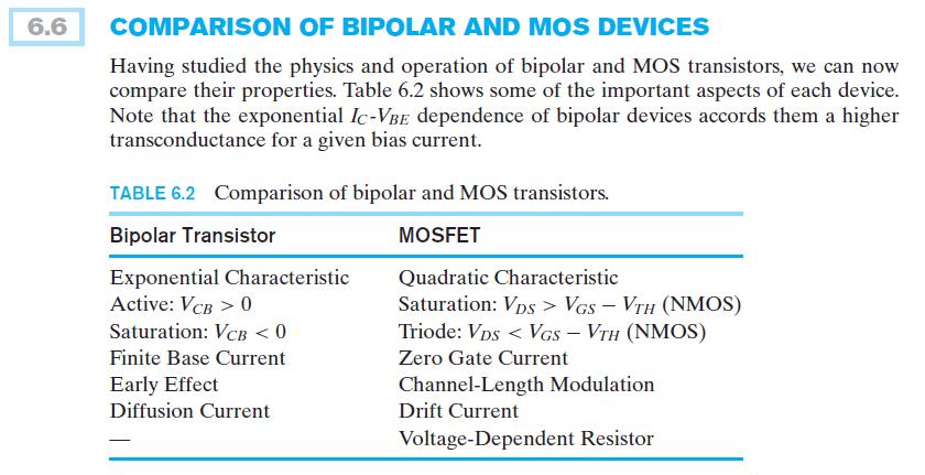
EE301 Electronics I , Fall
 EE301 Electronics I 2018-2019, Fall 1. Introduction to Microelectronics (1 Week/3 Hrs.) Introduction, Historical Background, Basic Consepts 2. Rewiev of Semiconductors (1 Week/3 Hrs.) Semiconductor materials
Field-Effect Transistor (FET) is one of the two major transistors; FET derives its name from its working mechanism;
 is one of the two major transistors; FET derives its name from its working mechanism;") Chapter 3 Field-Effect Transistors (FETs) 3.1 Introduction Field-Effect Transistor (FET) is one of the two major transistors; FET derives its name from its working mechanism; The concept has been known
Chapter 3 Field-Effect Transistors (FETs) 3.1 Introduction Field-Effect Transistor (FET) is one of the two major transistors; FET derives its name from its working mechanism; The concept has been known
UNIT 3: FIELD EFFECT TRANSISTORS
 FIELD EFFECT TRANSISTOR: UNIT 3: FIELD EFFECT TRANSISTORS The field effect transistor is a semiconductor device, which depends for its operation on the control of current by an electric field. There are
EE301 Electronics I , Fall
 EE301 Electronics I 2018-2019, Fall 1. Introduction to Microelectronics (1 Week/3 Hrs.) Introduction, Historical Background, Basic Consepts 2. Rewiev of Semiconductors (1 Week/3 Hrs.) Semiconductor materials
ECE520 VLSI Design. Lecture 2: Basic MOS Physics. Payman Zarkesh-Ha
 ECE520 VLSI Design Lecture 2: Basic MOS Physics Payman Zarkesh-Ha Office: ECE Bldg. 230B Office hours: Wednesday 2:00-3:00PM or by appointment E-mail: pzarkesh@unm.edu Slide: 1 Review of Last Lecture Semiconductor
Solid State Devices- Part- II. Module- IV
 Solid State Devices- Part- II Module- IV MOS Capacitor Two terminal MOS device MOS = Metal- Oxide- Semiconductor MOS capacitor - the heart of the MOSFET The MOS capacitor is used to induce charge at the
Semiconductor Physics and Devices
 Metal-Semiconductor and Semiconductor Heterojunctions The Metal-Oxide-Semiconductor Field-Effect Transistor (MOSFET) is one of two major types of transistors. The MOSFET is used in digital circuit, because
INTRODUCTION: Basic operating principle of a MOSFET:
 INTRODUCTION: Along with the Junction Field Effect Transistor (JFET), there is another type of Field Effect Transistor available whose Gate input is electrically insulated from the main current carrying
INTRODUCTION TO MOS TECHNOLOGY
 INTRODUCTION TO MOS TECHNOLOGY 1. The MOS transistor The most basic element in the design of a large scale integrated circuit is the transistor. For the processes we will discuss, the type of transistor
FIELD EFFECT TRANSISTOR (FET) 1. JUNCTION FIELD EFFECT TRANSISTOR (JFET)
 1. JUNCTION FIELD EFFECT TRANSISTOR (JFET)") FIELD EFFECT TRANSISTOR (FET) The field-effect transistor (FET) is a three-terminal device used for a variety of applications that match, to a large extent, those of the BJT transistor. Although there
FIELD EFFECT TRANSISTOR (FET) The field-effect transistor (FET) is a three-terminal device used for a variety of applications that match, to a large extent, those of the BJT transistor. Although there
Three Terminal Devices
 Three Terminal Devices - field effect transistor (FET) - bipolar junction transistor (BJT) - foundation on which modern electronics is built - active devices - devices described completely by considering
EE70 - Intro. Electronics
 EE70 - Intro. Electronics Course website: ~/classes/ee70/fall05 Today s class agenda (November 28, 2005) review Serial/parallel resonant circuits Diode Field Effect Transistor (FET) f 0 = Qs = Qs = 1 2π
Conduction Characteristics of MOS Transistors (for fixed Vds)! Topic 2. Basic MOS theory & SPICE simulation. MOS Transistor
! Topic 2. Basic MOS theory & SPICE simulation. MOS Transistor") Conduction Characteristics of MOS Transistors (for fixed Vds)! Topic 2 Basic MOS theory & SPICE simulation Peter Cheung Department of Electrical & Electronic Engineering Imperial College London (Weste&Harris,
Conduction Characteristics of MOS Transistors (for fixed Vds)! Topic 2 Basic MOS theory & SPICE simulation Peter Cheung Department of Electrical & Electronic Engineering Imperial College London (Weste&Harris,
Topic 2. Basic MOS theory & SPICE simulation
 Topic 2 Basic MOS theory & SPICE simulation Peter Cheung Department of Electrical & Electronic Engineering Imperial College London (Weste&Harris, Ch 2 & 5.1-5.3 Rabaey, Ch 3) URL: www.ee.ic.ac.uk/pcheung/
Conduction Characteristics of MOS Transistors (for fixed Vds) Topic 2. Basic MOS theory & SPICE simulation. MOS Transistor
 Topic 2. Basic MOS theory & SPICE simulation. MOS Transistor") Conduction Characteristics of MOS Transistors (for fixed Vds) Topic 2 Basic MOS theory & SPICE simulation Peter Cheung Department of Electrical & Electronic Engineering Imperial College London (Weste&Harris,
Conduction Characteristics of MOS Transistors (for fixed Vds) Topic 2 Basic MOS theory & SPICE simulation Peter Cheung Department of Electrical & Electronic Engineering Imperial College London (Weste&Harris,
(Refer Slide Time: 02:05)
") Electronics for Analog Signal Processing - I Prof. K. Radhakrishna Rao Department of Electrical Engineering Indian Institute of Technology Madras Lecture 27 Construction of a MOSFET (Refer Slide Time:
Electronics for Analog Signal Processing - I Prof. K. Radhakrishna Rao Department of Electrical Engineering Indian Institute of Technology Madras Lecture 27 Construction of a MOSFET (Refer Slide Time:
MOSFET & IC Basics - GATE Problems (Part - I)
") MOSFET & IC Basics - GATE Problems (Part - I) 1. Channel current is reduced on application of a more positive voltage to the GATE of the depletion mode n channel MOSFET. (True/False) [GATE 1994: 1 Mark]
MOSFET & IC Basics - GATE Problems (Part - I) 1. Channel current is reduced on application of a more positive voltage to the GATE of the depletion mode n channel MOSFET. (True/False) [GATE 1994: 1 Mark]
Lecture-45. MOS Field-Effect-Transistors Threshold voltage
 Lecture-45 MOS Field-Effect-Transistors 7.4. Threshold voltage In this section we summarize the calculation of the threshold voltage and discuss the dependence of the threshold voltage on the bias applied
8. Characteristics of Field Effect Transistor (MOSFET)
") 1 8. Characteristics of Field Effect Transistor (MOSFET) 8.1. Objectives The purpose of this experiment is to measure input and output characteristics of n-channel and p- channel field effect transistors
1 8. Characteristics of Field Effect Transistor (MOSFET) 8.1. Objectives The purpose of this experiment is to measure input and output characteristics of n-channel and p- channel field effect transistors
UNIT 3 Transistors JFET
 UNIT 3 Transistors JFET Mosfet Definition of BJT A bipolar junction transistor is a three terminal semiconductor device consisting of two p-n junctions which is able to amplify or magnify a signal. It
I E I C since I B is very small
 Figure 2: Symbols and nomenclature of a (a) npn and (b) pnp transistor. The BJT consists of three regions, emitter, base, and collector. The emitter and collector are usually of one type of doping, while
UNIT-1 Bipolar Junction Transistors. Text Book:, Microelectronic Circuits 6 ed., by Sedra and Smith, Oxford Press
 UNIT-1 Bipolar Junction Transistors Text Book:, Microelectronic Circuits 6 ed., by Sedra and Smith, Oxford Press Figure 6.1 A simplified structure of the npn transistor. Microelectronic Circuits, Sixth
UNIT-VI FIELD EFFECT TRANSISTOR. 1. Explain about the Field Effect Transistor and also mention types of FET s.
 UNIT-I FIELD EFFECT TRANSISTOR 1. Explain about the Field Effect Transistor and also mention types of FET s. The Field Effect Transistor, or simply FET however, uses the voltage that is applied to their
Difference between BJTs and FETs. Junction Field Effect Transistors (JFET)
") Difference between BJTs and FETs Transistors can be categorized according to their structure, and two of the more commonly known transistor structures, are the BJT and FET. The comparison between BJTs
Difference between BJTs and FETs Transistors can be categorized according to their structure, and two of the more commonly known transistor structures, are the BJT and FET. The comparison between BJTs
MEASUREMENT AND INSTRUMENTATION STUDY NOTES UNIT-I
 MEASUREMENT AND INSTRUMENTATION STUDY NOTES The MOSFET The MOSFET Metal Oxide FET UNIT-I As well as the Junction Field Effect Transistor (JFET), there is another type of Field Effect Transistor available
Design cycle for MEMS
 Design cycle for MEMS Design cycle for ICs IC Process Selection nmos CMOS BiCMOS ECL for logic for I/O and driver circuit for critical high speed parts of the system The Real Estate of a Wafer MOS Transistor
In this lecture we will begin a new topic namely the Metal-Oxide-Semiconductor Field Effect Transistor.
 Solid State Devices Dr. S. Karmalkar Department of Electronics and Communication Engineering Indian Institute of Technology, Madras Lecture - 38 MOS Field Effect Transistor In this lecture we will begin
Student Lecture by: Giangiacomo Groppi Joel Cassell Pierre Berthelot September 28 th 2004
 Student Lecture by: Giangiacomo Groppi Joel Cassell Pierre Berthelot September 28 th 2004 Lecture outline Historical introduction Semiconductor devices overview Bipolar Junction Transistor (BJT) Field
6. Field-Effect Transistor
 6. Outline: Introduction to three types of FET: JFET MOSFET & CMOS MESFET Constructions, Characteristics & Transfer curves of: JFET & MOSFET Introduction The field-effect transistor (FET) is a threeterminal
Basic Fabrication Steps
 Basic Fabrication Steps and Layout Somayyeh Koohi Department of Computer Engineering Adapted with modifications from lecture notes prepared by author Outline Fabrication steps Transistor structures Transistor
EE 5611 Introduction to Microelectronic Technologies Fall Thursday, September 04, 2014 Lecture 02
 EE 5611 Introduction to Microelectronic Technologies Fall 2014 Thursday, September 04, 2014 Lecture 02 1 Lecture Outline Review on semiconductor materials Review on microelectronic devices Example of microelectronic
BJT Amplifier. Superposition principle (linear amplifier)
") BJT Amplifier Two types analysis DC analysis Applied DC voltage source AC analysis Time varying signal source Superposition principle (linear amplifier) The response of a linear amplifier circuit excited
BJT Amplifier Two types analysis DC analysis Applied DC voltage source AC analysis Time varying signal source Superposition principle (linear amplifier) The response of a linear amplifier circuit excited
ECE 340 Lecture 37 : Metal- Insulator-Semiconductor FET Class Outline:
 ECE 340 Lecture 37 : Metal- Insulator-Semiconductor FET Class Outline: Metal-Semiconductor Junctions MOSFET Basic Operation MOS Capacitor Things you should know when you leave Key Questions What is the
Laboratory #5 BJT Basics and MOSFET Basics
 Laboratory #5 BJT Basics and MOSFET Basics I. Objectives 1. Understand the physical structure of BJTs and MOSFETs. 2. Learn to measure I-V characteristics of BJTs and MOSFETs. II. Components and Instruments
Week 7: Common-Collector Amplifier, MOS Field Effect Transistor
 EE 2110A Electronic Circuits Week 7: Common-Collector Amplifier, MOS Field Effect Transistor ecture 07-1 Topics to coer Common-Collector Amplifier MOS Field Effect Transistor Physical Operation and I-V
FET. Field Effect Transistors ELEKTRONIKA KONTROL. Eka Maulana, ST, MT, M.Eng. Universitas Brawijaya. p + S n n-channel. Gate. Basic structure.
 FET Field Effect Transistors ELEKTRONIKA KONTROL Basic structure Gate G Source S n n-channel Cross section p + p + p + G Depletion region Drain D Eka Maulana, ST, MT, M.Eng. Universitas Brawijaya S Channel
Transistor was first invented by William.B.Shockley, Walter Brattain and John Bardeen of Bell Labratories. In 1961, first IC was introduced.
 Unit 1 Basic MOS Technology Transistor was first invented by William.B.Shockley, Walter Brattain and John Bardeen of Bell Labratories. In 1961, first IC was introduced. Levels of Integration:- i) SSI:-
An introduction to Depletion-mode MOSFETs By Linden Harrison
 An introduction to Depletion-mode MOSFETs By Linden Harrison Since the mid-nineteen seventies the enhancement-mode MOSFET has been the subject of almost continuous global research, development, and refinement
MOS Field-Effect Transistors (MOSFETs)
") 6 MOS Field-Effect Transistors (MOSFETs) A three-terminal device that uses the voltages of the two terminals to control the current flowing in the third terminal. The basis for amplifier design. The basis
6 MOS Field-Effect Transistors (MOSFETs) A three-terminal device that uses the voltages of the two terminals to control the current flowing in the third terminal. The basis for amplifier design. The basis
MOSFET Terminals. The voltage applied to the GATE terminal determines whether current can flow between the SOURCE & DRAIN terminals.
 MOSFET Terminals The voltage applied to the GATE terminal determines whether current can flow between the SOURCE & DRAIN terminals. For an n-channel MOSFET, the SOURCE is biased at a lower potential (often
UNIVERSITY OF CALIFORNIA AT BERKELEY College of Engineering Department of Electrical Engineering and Computer Sciences.
 UNIVERSITY OF CALIFORNIA AT BERKELEY College of Engineering Department of Electrical Engineering and Computer Sciences Discussion #9 EE 05 Spring 2008 Prof. u MOSFETs The standard MOSFET structure is shown
Digital Electronics. By: FARHAD FARADJI, Ph.D. Assistant Professor, Electrical and Computer Engineering, K. N. Toosi University of Technology
 K. N. Toosi University of Technology Chapter 7. Field-Effect Transistors By: FARHAD FARADJI, Ph.D. Assistant Professor, Electrical and Computer Engineering, K. N. Toosi University of Technology http://wp.kntu.ac.ir/faradji/digitalelectronics.htm
Lesson 5. Electronics: Semiconductors Doping p-n Junction Diode Half Wave and Full Wave Rectification Introduction to Transistors-
 Lesson 5 Electronics: Semiconductors Doping p-n Junction Diode Half Wave and Full Wave Rectification Introduction to Transistors- Types and Connections Semiconductors Semiconductors If there are many free
Department of Electrical Engineering IIT Madras
 Department of Electrical Engineering IIT Madras Sample Questions on Semiconductor Devices EE3 applicants who are interested to pursue their research in microelectronics devices area (fabrication and/or
55:041 Electronic Circuits
 55:041 Electronic Circuits Mosfet Review Sections of Chapter 3 &4 A. Kruger Mosfet Review, Page-1 Basic Structure of MOS Capacitor Sect. 3.1 Width 1 10-6 m or less Thickness 50 10-9 m or less ` MOS Metal-Oxide-Semiconductor
Lecture 16: MOS Transistor models: Linear models, SPICE models. Context. In the last lecture, we discussed the MOS transistor, and
 Lecture 16: MOS Transistor models: Linear models, SPICE models Context In the last lecture, we discussed the MOS transistor, and added a correction due to the changing depletion region, called the body
Unit III FET and its Applications. 2 Marks Questions and Answers
 Unit III FET and its Applications 2 Marks Questions and Answers 1. Why do you call FET as field effect transistor? The name field effect is derived from the fact that the current is controlled by an electric
Session 10: Solid State Physics MOSFET
 Session 10: Solid State Physics MOSFET 1 Outline A B C D E F G H I J 2 MOSCap MOSFET Metal-Oxide-Semiconductor Field-Effect Transistor: Al (metal) SiO2 (oxide) High k ~0.1 ~5 A SiO2 A n+ n+ p-type Si (bulk)
Depletion-mode operation ( 공핍형 ): Using an input gate voltage to effectively decrease the channel size of an FET
: Using an input gate voltage to effectively decrease the channel size of an FET") Ch. 13 MOSFET Metal-Oxide-Semiconductor Field-Effect Transistor : I D D-mode E-mode V g The gate oxide is made of dielectric SiO 2 with e = 3.9 Depletion-mode operation ( 공핍형 ): Using an input gate voltage
Ch. 13 MOSFET Metal-Oxide-Semiconductor Field-Effect Transistor : I D D-mode E-mode V g The gate oxide is made of dielectric SiO 2 with e = 3.9 Depletion-mode operation ( 공핍형 ): Using an input gate voltage
Module-3: Metal Oxide Semiconductor (MOS) & Emitter coupled logic (ECL) families
 & Emitter coupled logic (ECL) families") 1 Module-3: Metal Oxide Semiconductor (MOS) & Emitter coupled logic (ECL) families 1. Introduction 2. Metal Oxide Semiconductor (MOS) logic 2.1. Enhancement and depletion mode 2.2. NMOS and PMOS inverter
1 Module-3: Metal Oxide Semiconductor (MOS) & Emitter coupled logic (ECL) families 1. Introduction 2. Metal Oxide Semiconductor (MOS) logic 2.1. Enhancement and depletion mode 2.2. NMOS and PMOS inverter
Lecture 15. Field Effect Transistor (FET) Wednesday 29/11/2017 MOSFET 1-1
 Wednesday 29/11/2017 MOSFET 1-1") Lecture 15 Field Effect Transistor (FET) Wednesday 29/11/2017 MOSFET 1-1 Outline MOSFET transistors Introduction to MOSFET MOSFET Types epletion-type MOSFET Characteristics Comparison between JFET and
Lecture 15 Field Effect Transistor (FET) Wednesday 29/11/2017 MOSFET 1-1 Outline MOSFET transistors Introduction to MOSFET MOSFET Types epletion-type MOSFET Characteristics Comparison between JFET and
Exam Below are two schematics of current sources implemented with MOSFETs. Which current source has the best compliance voltage?
 Exam 2 Name: Score /90 Question 1 Short Takes 1 point each unless noted otherwise. 1. Below are two schematics of current sources implemented with MOSFETs. Which current source has the best compliance
Basic Electronics Prof. Dr. Chitralekha Mahanta Department of Electronics and Communication Engineering Indian Institute of Technology, Guwahati
 Basic Electronics Prof. Dr. Chitralekha Mahanta Department of Electronics and Communication Engineering Indian Institute of Technology, Guwahati Module: 3 Field Effect Transistors Lecture-7 High Frequency
Lecture 3: Transistors
 Lecture 3: Transistors Now that we know about diodes, let s put two of them together, as follows: collector base emitter n p n moderately doped lightly doped, and very thin heavily doped At first glance,
Chapter 8. Field Effect Transistor
 Chapter 8. Field Effect Transistor Field Effect Transistor: The field effect transistor is a semiconductor device, which depends for its operation on the control of current by an electric field. There
COLLECTOR DRAIN BASE GATE EMITTER. Applying a voltage to the Gate connection allows current to flow between the Drain and Source connections.
 MOSFETS Although the base current in a transistor is usually small (< 0.1 ma), some input devices (e.g. a crystal microphone) may be limited in their output. In order to overcome this, a Field Effect Transistor
Basic Electronics. Introductory Lecture Course for. Technology and Instrumentation in Particle Physics Chicago, Illinois June 9-14, 2011
 Basic Electronics Introductory Lecture Course for Technology and Instrumentation in Particle Physics 2011 Chicago, Illinois June 9-14, 2011 Presented By Gary Drake Argonne National Laboratory Session 3
Field Effect Transistor (FET) FET 1-1
 FET 1-1") Field Effect Transistor (FET) FET 1-1 Outline MOSFET transistors ntroduction to MOSFET MOSFET Types epletion-type MOSFET Characteristics Biasing Circuits and Examples Comparison between JFET and epletion-type
Field Effect Transistor (FET) FET 1-1 Outline MOSFET transistors ntroduction to MOSFET MOSFET Types epletion-type MOSFET Characteristics Biasing Circuits and Examples Comparison between JFET and epletion-type
SRM INSTITUTE OF SCIENCE AND TECHNOLOGY (DEEMED UNIVERSITY)
") SRM INSTITUTE OF SCIENCE AND TECHNOLOGY (DEEMED UNIVERSITY) QUESTION BANK I YEAR B.Tech (II Semester) ELECTRONIC DEVICES (COMMON FOR EC102, EE104, IC108, BM106) UNIT-I PART-A 1. What are intrinsic and
SRM INSTITUTE OF SCIENCE AND TECHNOLOGY (DEEMED UNIVERSITY) QUESTION BANK I YEAR B.Tech (II Semester) ELECTRONIC DEVICES (COMMON FOR EC102, EE104, IC108, BM106) UNIT-I PART-A 1. What are intrinsic and
55:041 Electronic Circuits
 55:041 Electronic Circuits MOSFETs Sections of Chapter 3 &4 A. Kruger MOSFETs, Page-1 Basic Structure of MOS Capacitor Sect. 3.1 Width = 1 10-6 m or less Thickness = 50 10-9 m or less ` MOS Metal-Oxide-Semiconductor
Notes. (Subject Code: 7EC5)
") COMPUCOM INSTITUTE OF TECHNOLOGY & MANAGEMENT, JAIPUR (DEPARTMENT OF ELECTRONICS & COMMUNICATION) Notes VLSI DESIGN NOTES (Subject Code: 7EC5) Prepared By: MANVENDRA SINGH Class: B. Tech. IV Year, VII
COMPUCOM INSTITUTE OF TECHNOLOGY & MANAGEMENT, JAIPUR (DEPARTMENT OF ELECTRONICS & COMMUNICATION) Notes VLSI DESIGN NOTES (Subject Code: 7EC5) Prepared By: MANVENDRA SINGH Class: B. Tech. IV Year, VII
Chapter 5. Operational Amplifiers and Source Followers. 5.1 Operational Amplifier
 Chapter 5 Operational Amplifiers and Source Followers 5.1 Operational Amplifier In single ended operation the output is measured with respect to a fixed potential, usually ground, whereas in double-ended
Chapter 4. CMOS Cascode Amplifiers. 4.1 Introduction. 4.2 CMOS Cascode Amplifiers
 Chapter 4 CMOS Cascode Amplifiers 4.1 Introduction A single stage CMOS amplifier cannot give desired dc voltage gain, output resistance and transconductance. The voltage gain can be made to attain higher
KOM2751 Analog Electronics :: Dr. Muharrem Mercimek :: YTU - Control and Automation Dept. 1 6 FIELD-EFFECT TRANSISTORS
 KOM2751 Analog Electronics :: Dr. Muharrem Mercimek :: YTU - Control and Automation Dept. 1 6 FIELD-EFFECT TRANSISTORS Most of the content is from the textbook: Electronic devices and circuit theory, Robert
Field Effect Transistors (npn)
") Field Effect Transistors (npn) gate drain source FET 3 terminal device channel e - current from source to drain controlled by the electric field generated by the gate base collector emitter BJT 3 terminal
Field Effect Transistors (npn) gate drain source FET 3 terminal device channel e - current from source to drain controlled by the electric field generated by the gate base collector emitter BJT 3 terminal
Prof. Paolo Colantonio a.a
 Prof. Paolo Colantonio a.a. 20 2 Field effect transistors (FETs) are probably the simplest form of transistor, widely used in both analogue and digital applications They are characterised by a very high
Introduction to MOSFET MOSFET (Metal Oxide Semiconductor Field Effect Transistor)
") Microelectronic Circuits Introduction to MOSFET MOSFET (Metal Oxide Semiconductor Field Effect Transistor) Slide 1 MOSFET Construction MOSFET (Metal Oxide Semiconductor Field Effect Transistor) Slide 2
Microelectronic Circuits Introduction to MOSFET MOSFET (Metal Oxide Semiconductor Field Effect Transistor) Slide 1 MOSFET Construction MOSFET (Metal Oxide Semiconductor Field Effect Transistor) Slide 2
Lecture 2 p-n junction Diode characteristics. By Asst. Prof Dr. Jassim K. Hmood
 Electronic I Lecture 2 p-n junction Diode characteristics By Asst. Prof Dr. Jassim K. Hmood THE p-n JUNCTION DIODE The pn junction diode is formed by fabrication of a p-type semiconductor region in intimate
CHAPTER 8 FIELD EFFECT TRANSISTOR (FETs)
") CHAPTER 8 FIELD EFFECT TRANSISTOR (FETs) INTRODUCTION - FETs are voltage controlled devices as opposed to BJT which are current controlled. - There are two types of FETs. o Junction FET (JFET) o Metal
CHAPTER 8 FIELD EFFECT TRANSISTOR (FETs) INTRODUCTION - FETs are voltage controlled devices as opposed to BJT which are current controlled. - There are two types of FETs. o Junction FET (JFET) o Metal
Field Effect Transistors
 Field Effect Transistors LECTURE NO. - 41 Field Effect Transistors www.mycsvtunotes.in JFET MOSFET CMOS Field Effect transistors - FETs First, why are we using still another transistor? BJTs had a small
Chapter 2 : Semiconductor Materials & Devices (II) Feb
 Feb") Chapter 2 : Semiconductor Materials & Devices (II) 1 Reference 1. SemiconductorManufacturing Technology: Michael Quirk and Julian Serda (2001) 3. Microelectronic Circuits (5/e): Sedra & Smith (2004) 4.
Chapter 2 : Semiconductor Materials & Devices (II) 1 Reference 1. SemiconductorManufacturing Technology: Michael Quirk and Julian Serda (2001) 3. Microelectronic Circuits (5/e): Sedra & Smith (2004) 4.
97.398*, Physical Electronics, Lecture 21. MOSFET Operation
 97.398*, Physical Electronics, Lecture 21 MOSFET Operation Lecture Outline Last lecture examined the MOSFET structure and required processing steps Now move on to basic MOSFET operation, some of which
EIE209 Basic Electronics. Transistor Devices. Contents BJT and FET Characteristics Operations. Prof. C.K. Tse: T ransistor devices
 EIE209 Basic Electronics Transistor Devices Contents BJT and FET Characteristics Operations 1 What is a transistor? Three-terminal device whose voltage-current relationship is controlled by a third voltage
Lecture - 18 Transistors
 Electronic Materials, Devices and Fabrication Dr. S. Prarasuraman Department of Metallurgical and Materials Engineering Indian Institute of Technology, Madras Lecture - 18 Transistors Last couple of classes
MODULE-2: Field Effect Transistors (FET)
") FORMAT-1B Definition: MODULE-2: Field Effect Transistors (FET) FET is a three terminal electronic device used for variety of applications that match with BJT. In FET, an electric field is established by
FORMAT-1B Definition: MODULE-2: Field Effect Transistors (FET) FET is a three terminal electronic device used for variety of applications that match with BJT. In FET, an electric field is established by
Physics 364, Fall 2012, reading due your answers to by 11pm on Thursday
 Physics 364, Fall 2012, reading due 2012-10-25. Email your answers to ashmansk@hep.upenn.edu by 11pm on Thursday Course materials and schedule are at http://positron.hep.upenn.edu/p364 Assignment: (a)
FET(Field Effect Transistor)
") Field Effect Transistor: Construction and Characteristic of JFETs. Transfer Characteristic. CS,CD,CG amplifier and analysis of CS amplifier MOSFET (Depletion and Enhancement) Type, Transfer Characteristic,
Field Effect Transistor: Construction and Characteristic of JFETs. Transfer Characteristic. CS,CD,CG amplifier and analysis of CS amplifier MOSFET (Depletion and Enhancement) Type, Transfer Characteristic,
Chapter 5: Field Effect Transistors
 Chapter 5: Field Effect Transistors Slide 1 FET FET s (Field Effect Transistors) are much like BJT s (Bipolar Junction Transistors). Similarities: Amplifiers Switching devices Impedance matching circuits
EE105 Fall 2015 Microelectronic Devices and Circuits: MOSFET Prof. Ming C. Wu 511 Sutardja Dai Hall (SDH)
") EE105 Fall 2015 Microelectronic Devices and Circuits: MOSFET Prof. Ming C. Wu wu@eecs.berkeley.edu 511 Sutardja Dai Hall (SDH) 7-1 Simplest Model of MOSFET (from EE16B) 7-2 CMOS Inverter 7-3 CMOS NAND
EE105 Fall 2015 Microelectronic Devices and Circuits: MOSFET Prof. Ming C. Wu wu@eecs.berkeley.edu 511 Sutardja Dai Hall (SDH) 7-1 Simplest Model of MOSFET (from EE16B) 7-2 CMOS Inverter 7-3 CMOS NAND
FUNDAMENTALS OF MODERN VLSI DEVICES
 19-13- FUNDAMENTALS OF MODERN VLSI DEVICES YUAN TAUR TAK H. MING CAMBRIDGE UNIVERSITY PRESS Physical Constants and Unit Conversions List of Symbols Preface page xi xiii xxi 1 INTRODUCTION I 1.1 Evolution
MOS Field Effect Transistors
 MOS Field Effect Transistors A gate contact gate interconnect n polysilicon gate source contacts W active area (thin oxide area) polysilicon gate contact metal interconnect drain contacts A bulk contact
MOS Transistor Theory
 MOS Transistor Theory So far, we have viewed a MOS transistor as an ideal switch (digital operation) Reality: less than ideal EE 261 Krish Chakrabarty 1 MOS Transistor Theory Study conducting channel between
4.1 Device Structure and Physical Operation
 10/12/2004 4_1 Device Structure and Physical Operation blank.doc 1/2 4.1 Device Structure and Physical Operation Reading Assignment: pp. 235-248 Chapter 4 covers Field Effect Transistors ( ) Specifically,
Lecture 13. Metal Oxide Semiconductor Field Effect Transistor (MOSFET) MOSFET 1-1
 MOSFET 1-1") Lecture 13 Metal Oxide Semiconductor Field Effect Transistor (MOSFET) MOSFET 1-1 Outline Continue MOSFET Qualitative Operation epletion-type MOSFET Characteristics Biasing Circuits and Examples Enhancement-type
Lecture 13 Metal Oxide Semiconductor Field Effect Transistor (MOSFET) MOSFET 1-1 Outline Continue MOSFET Qualitative Operation epletion-type MOSFET Characteristics Biasing Circuits and Examples Enhancement-type
Experiment 3. 3 MOSFET Drain Current Modeling. 3.1 Summary. 3.2 Theory. ELEC 3908 Experiment 3 Student#:
 Experiment 3 3 MOSFET Drain Current Modeling 3.1 Summary In this experiment I D vs. V DS and I D vs. V GS characteristics are measured for a silicon MOSFET, and are used to determine the parameters necessary
Integrated diodes. The forward voltage drop only slightly depends on the forward current. ELEKTRONIKOS ĮTAISAI
 1 Integrated diodes pn junctions of transistor structures can be used as integrated diodes. The choice of the junction is limited by the considerations of switching speed and breakdown voltage. The forward
TECHNO INDIA BATANAGAR (DEPARTMENT OF ELECTRONICS & COMMUNICATION ENGINEERING) QUESTION BANK- 2018
 QUESTION BANK- 2018") TECHNO INDIA BATANAGAR (DEPARTMENT OF ELECTRONICS & COMMUNICATION ENGINEERING) QUESTION BANK- 2018 Paper Setter Detail Name Designation Mobile No. E-mail ID Raina Modak Assistant Professor 6290025725 raina.modak@tib.edu.in
TECHNO INDIA BATANAGAR (DEPARTMENT OF ELECTRONICS & COMMUNICATION ENGINEERING) QUESTION BANK- 2018 Paper Setter Detail Name Designation Mobile No. E-mail ID Raina Modak Assistant Professor 6290025725 raina.modak@tib.edu.in
Power Bipolar Junction Transistors (BJTs)
") ECE442 Power Semiconductor Devices and Integrated Circuits Power Bipolar Junction Transistors (BJTs) Zheng Yang (ERF 3017, email: yangzhen@uic.edu) Power Bipolar Junction Transistor (BJT) Background The
ECE442 Power Semiconductor Devices and Integrated Circuits Power Bipolar Junction Transistors (BJTs) Zheng Yang (ERF 3017, email: yangzhen@uic.edu) Power Bipolar Junction Transistor (BJT) Background The
Field Effect Transistors
 Chapter 5: Field Effect Transistors Slide 1 FET FET s (Field Effect Transistors) are much like BJT s (Bipolar Junction Transistors). Similarities: Amplifiers Switching devices Impedance matching circuits
Analog IC Design. Lecture 1,2: Introduction & MOS transistors. Henrik Sjöland. Dept. of Electrical and Information Technology
 Analog IC Design Lecture 1,2: Introduction & MOS transistors Henrik.Sjoland@eit.lth.se Part 1: Introduction Analogue IC Design (7.5hp, lp2) CMOS Technology Analog building blocks in CMOS Single- and multiple
MOSFET short channel effects
 MOSFET short channel effects overview Five different short channel effects can be distinguished: velocity saturation drain induced barrier lowering (DIBL) impact ionization surface scattering hot electrons
Sub-Threshold Region Behavior of Long Channel MOSFET
 Sub-threshold Region - So far, we have discussed the MOSFET behavior in linear region and saturation region - Sub-threshold region is refer to region where Vt is less than Vt - Sub-threshold region reflects
EDC UNIT IV- Transistor and FET Characteristics EDC Lesson 9- ", Raj Kamal, 1
 EDC UNIT IV- Transistor and FET Characteristics Lesson-9: JFET and Construction of JFET 2008 EDC Lesson 9- ", Raj Kamal, 1 1. Transistor 2008 EDC Lesson 9- ", Raj Kamal, 2 Transistor Definition The transferred-resistance
Power MOSFET Zheng Yang (ERF 3017,
 ECE442 Power Semiconductor Devices and Integrated Circuits Power MOSFET Zheng Yang (ERF 3017, email: yangzhen@uic.edu) Evolution of low-voltage (
Organic Electronics. Information: Information: 0331a/ 0442/
 Organic Electronics (Course Number 300442 ) Spring 2006 Organic Field Effect Transistors Instructor: Dr. Dietmar Knipp Information: Information: http://www.faculty.iubremen.de/course/c30 http://www.faculty.iubremen.de/course/c30
444 Index. F Fermi potential, 146 FGMOS transistor, 20 23, 57, 83, 84, 98, 205, 208, 213, 215, 216, 241, 242, 251, 280, 311, 318, 332, 354, 407
 Index A Accuracy active resistor structures, 46, 323, 328, 329, 341, 344, 360 computational circuits, 171 differential amplifiers, 30, 31 exponential circuits, 285, 291, 292 multifunctional structures,
problem grade total
 Fall 2005 6.012 Microelectronic Devices and Circuits Prof. J. A. del Alamo Name: Recitation: November 16, 2005 Quiz #2 problem grade 1 2 3 4 total General guidelines (please read carefully before starting):
FIELD EFFECT TRANSISTORS MADE BY : GROUP (13)/PM
/PM") FIELD EFFECT TRANSISTORS MADE BY : GROUP (13)/PM THE FIELD EFFECT TRANSISTOR (FET) In 1945, Shockley had an idea for making a solid state device out of semiconductors. He reasoned that a strong electrical
FIELD EFFECT TRANSISTORS MADE BY : GROUP (13)/PM THE FIELD EFFECT TRANSISTOR (FET) In 1945, Shockley had an idea for making a solid state device out of semiconductors. He reasoned that a strong electrical
Solid State Device Fundamentals
 Solid State Device Fundamentals 4.4. Field Effect Transistor (MOSFET) ENS 463 Lecture Course by Alexander M. Zaitsev alexander.zaitsev@csi.cuny.edu Tel: 718 982 2812 4N101b 1 Field-effect transistor (FET)
ECE 440 Lecture 39 : MOSFET-II
 ECE 440 Lecture 39 : MOSFETII Class Outline: MOSFET Qualitative Effective Mobility MOSFET Quantitative Things you should know when you leave Key Questions How does a MOSFET work? Why does the channel mobility