FET. Field Effect Transistors ELEKTRONIKA KONTROL. Eka Maulana, ST, MT, M.Eng. Universitas Brawijaya. p + S n n-channel. Gate. Basic structure.
|
|
|
- Lillian Peters
- 5 years ago
- Views:
Transcription


1 FET Field Effect Transistors ELEKTRONIKA KONTROL Basic structure Gate G Source S n n-channel Cross section p + p + p + G Depletion region Drain D Eka Maulana, ST, MT, M.Eng. Universitas Brawijaya S Channel thickness n p + n-channel (a) n D

2 INTRODUCTION TO FET FET: FIELD EFFECT TRANSISTOR THERE ARE TWO TYPES JFET: JUNCTION FET MOSFET: METAL-OXIDE-SEMICONDUCTOR FET MOSFET IS ALSO CALLED THE INSULATED-GATE FET OR IGFET. QUITE SMALL SIMPLE MANUFACTURING PROCESS LOW POWER CONSUMPTION WIDELY USED IN VLSI CIRCUITS(>800 MILLION ON A SINGLE IC CHIP) 2
3 3 CLASSIFICATION OF FET ACCORDING TO THE TYPE OF THE CHANNEL, FETS CAN BE CLASSIFIED AS JFET P CHANNEL N CHANNEL MOSFET N CHANNEL P CHANNEL Enhancement type Depletion type Enhancement type Depletion type
4 SIMBOL JFET DAN MOSFET 4
5 THE FIELD EFFECT TRANSISTOR (FET) IN 1945, SHOCKLEY HAD AN IDEA FOR MAKING A SOLID STATE DEVICE OUT OF SEMICONDUCTORS. HE REASONED THAT A STRONG ELECTRICAL FIELD COULD CAUSE THE FLOW OF ELECTRICITY WITHIN A NEARBY SEMICONDUCTOR. HE TRIED TO BUILD ONE, BUT IT DIDN'T WORK. THREE YEARS LATER, BRATTAIN & BARDEEN BUILT THE FIRST WORKING TRANSISTOR, THE GERMANIUM POINT-CONTACT TRANSISTOR, WHICH WAS DESIGNED AS THE JUNCTION (SANDWICH) TRANSISTOR. IN 1960 BELL SCIENTIST JOHN ATALLA DEVELOPED A NEW DESIGN BASED ON SHOCKLEY'S ORIGINAL FIELD-EFFECT THEORIES. BY THE LATE 1960S, MANUFACTURERS CONVERTED FROM JUNCTION TYPE INTEGRATED CIRCUITS TO FIELD EFFECT DEVICES.
6 THE FIELD EFFECT TRANSISTOR (FET) FIELD EFFECT DEVICES ARE THOSE IN WHICH CURRENT IS CONTROLLED BY THE ACTION OF AN ELECTRON FIELD, RATHER THAN CARRIER INJECTION. FIELD-EFFECT TRANSISTORS ARE SO NAMED BECAUSE A WEAK ELECTRICAL SIGNAL COMING IN THROUGH ONE ELECTRODE CREATES AN ELECTRICAL FIELD THROUGH THE REST OF THE TRANSISTOR. THE FET WAS KNOWN AS A UNIPOLAR TRANSISTOR. THE TERM REFERS TO THE FACT THAT CURRENT IS TRANSPORTED BY CARRIERS OF ONE POLARITY (MAJORITY), WHEREAS IN THE CONVENTIONAL BIPOLAR TRANSISTOR CARRIERS OF BOTH POLARITIES (MAJORITY AND MINORITY) ARE INVOLVED.
7
8 OPERASI JFET 8
9 JUNCTION FET D Depletion layer G N-channel P + P + n-type Semiconductor G D S S 9

10 10 PHYSICAL OPERATION UNDER V DS =0 D D D P + G P + G P+ P + G P+ P + S S S U GS = 0 U GS < 0 U GS = U GS(off)


11 The effect of U DS on I D for U GS(off) <U GS < 0 11
12 TEST 12
13 TEST MODE ENHANCEMENT 13
14 RANGKAIAN COPER FET 14
")
15 Specification Sheet (JFETs)
16 CASE CONSTRUCTION AND TERMINAL IDENTIFICATION
17 IRFZ44 DATASHEET
18 JUNCTION FETS (JFETS) JFETS CONSISTS OF A PIECE OF HIGH-RESISTIVITY SEMICONDUCTOR MATERIAL (USUALLY SI) WHICH CONSTITUTES A CHANNEL FOR THE MAJORITY CARRIER FLOW. CONDUCTING SEMICONDUCTOR CHANNEL BETWEEN TWO OHMIC CONTACTS SOURCE & DRAIN
19 JUNCTION FETS (JFETS) THE MAGNITUDE OF THIS CURRENT IS CONTROLLED BY A VOLTAGE APPLIED TO A GATE, WHICH IS A REVERSE-BIASED. THE FUNDAMENTAL DIFFERENCE BETWEEN JFET AND BJT DEVICES: WHEN THE JFET JUNCTION IS REVERSE-BIASED THE GATE CURRENT IS PRACTICALLY ZERO, WHEREAS THE BASE CURRENT OF THE BJT IS ALWAYS SOME VALUE GREATER THAN ZERO.
20 JUNCTION FETS JFET IS A HIGH-INPUT RESISTANCE DEVICE, WHILE THE BJT IS COMPARATIVELY LOW. IF THE CHANNEL IS DOPED WITH A DONOR IMPURITY, N-TYPE MATERIAL IS FORMED AND THE CHANNEL CURRENT WILL CONSIST OF ELECTRONS. IF THE CHANNEL IS DOPED WITH AN ACCEPTOR IMPURITY, P-TYPE MATERIAL WILL BE FORMED AND THE CHANNEL CURRENT WILL CONSIST OF HOLES. N-CHANNEL DEVICES HAVE GREATER CONDUCTIVITY THAN P-CHANNEL TYPES, SINCE ELECTRONS HAVE HIGHER MOBILITY THAN DO HOLES; THUS N-CHANNEL JFETS ARE APPROXIMATELY TWICE AS EFFICIENT CONDUCTORS COMPARED TO THEIR P-CHANNEL COUNTERPARTS.
21 BASIC STRUCTURE OF JFETS IN ADDITION TO THE CHANNEL, A JFET CONTAINS TWO OHMIC CONTACTS: THE SOURCE AND THE DRAIN. THE JFET WILL CONDUCT CURRENT EQUALLY WELL IN EITHER DIRECTION AND THE SOURCE AND DRAIN LEADS ARE USUALLY INTERCHANGEABLE.
 S Channel thickness n p + n-channel n D (b)")
22 Basic structure Source S Cross section n p + p + p + n-channel G Gate G Depletion region Drain D Circuit symbol for n-channel FET Depletion regions n-channel S n S G G p D p + D Metal electrode Insulation (SiO 2 ) S Channel thickness n p + n-channel n D (b) (a)
23 N-CHANNEL JFET THIS TRANSISTOR IS MADE BY FORMING A CHANNEL OF N- TYPE MATERIAL IN A P-TYPE SUBSTRATE. THREE WIRES ARE THEN CONNECTED TO THE DEVICE. ONE AT EACH END OF THE CHANNEL. ONE CONNECTED TO THE SUBSTRATE. IN A SENSE, THE DEVICE IS A BIT LIKE A PN-JUNCTION DIODE, EXCEPT THAT THERE ARE TWO WIRES CONNECTED TO THE N-TYPE SIDE.
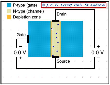
24 HOW JFET FUNCTION THE GATE IS CONNECTED TO THE SOURCE. SINCE THE PN JUNCTION IS REVERSE-BIASED, LITTLE CURRENT WILL FLOW IN THE GATE CONNECTION. THE POTENTIAL GRADIENT ESTABLISHED WILL FORM A DEPLETION LAYER, WHERE ALMOST ALL THE ELECTRONS PRESENT IN THE N-TYPE CHANNEL WILL BE SWEPT AWAY. THE MOST DEPLETED PORTION IS IN THE HIGH FIELD BETWEEN THE G AND THE D, AND THE LEAST-DEPLETED AREA IS BETWEEN THE G AND THE S.
25 HOW JFET FUNCTION BECAUSE THE FLOW OF CURRENT ALONG THE CHANNEL FROM THE (+VE) DRAIN TO THE (-VE) SOURCE IS REALLY A FLOW OF FREE ELECTRONS FROM S TO D IN THE N- TYPE SI, THE MAGNITUDE OF THIS CURRENT WILL FALL AS MORE SI BECOMES DEPLETED OF FREE ELECTRONS. THERE IS A LIMIT TO THE DRAIN CURRENT (I D ) WHICH INCREASED V DS CAN DRIVE THROUGH THE CHANNEL. THIS LIMITING CURRENT IS KNOWN AS I DSS (DRAIN-TO-SOURCE CURRENT WITH THE GATE SHORTED TO THE SOURCE).
26 THE OUTPUT CHARACTERISTICS OF AN N-CHANNEL JFET WITH THE GATE SHORT-CIRCUITED TO THE SOURCE. THE INITIAL RISE IN I D IS RELATED TO THE BUILDUP OF THE DEPLETION LAYER AS V DS INCREASES. THE CURVE APPROACHES THE LEVEL OF THE LIMITING CURRENT I DSS WHEN I D BEGINS TO BE PINCHED OFF. THE PHYSICAL MEANING OF THIS TERM LEADS TO ONE DEFINITION OF PINCH-OFF VOLTAGE, V P, WHICH IS THE VALUE OF V DS AT WHICH THE MAXIMUM I DSS FLOWS.

27 WITH A STEADY GATE-SOURCE VOLTAGE OF 1 V THERE IS ALWAYS 1 V ACROSS THE WALL OF THE CHANNEL AT THE SOURCE END. A DRAIN-SOURCE VOLTAGE OF 1 V MEANS THAT THERE WILL BE 2 V ACROSS THE WALL AT THE DRAIN END. (THE DRAIN IS UP 1V FROM THE SOURCE POTENTIAL AND THE GATE IS 1V DOWN, HENCE THE TOTAL DIFFERENCE IS 2V.) THE HIGHER VOLTAGE DIFFERENCE AT THE DRAIN END MEANS THAT THE ELECTRON CHANNEL IS SQUEEZED DOWN A BIT MORE AT THIS END.

28 WHEN THE DRAIN-SOURCE VOLTAGE IS INCREASED TO 10V THE VOLTAGE ACROSS THE CHANNEL WALLS AT THE DRAIN END INCREASES TO 11V, BUT REMAINS JUST 1V AT THE SOURCE END. THE FIELD ACROSS THE WALLS NEAR THE DRAIN END IS NOW A LOT LARGER THAN AT THE SOURCE END. AS A RESULT THE CHANNEL NEAR THE DRAIN IS SQUEEZED DOWN QUITE A LOT.

29 INCREASING THE SOURCE-DRAIN VOLTAGE TO 20V SQUEEZES DOWN THIS END OF THE CHANNEL STILL MORE. AS WE INCREASE THIS VOLTAGE WE INCREASE THE ELECTRIC FIELD WHICH DRIVES ELECTRONS ALONG THE OPEN PART OF THE CHANNEL. HOWEVER, ALSO SQUEEZES DOWN THE CHANNEL NEAR THE DRAIN END. THIS REDUCTION IN THE OPEN CHANNEL WIDTH MAKES IT HARDER FOR ELECTRONS TO PASS. AS A RESULT THE DRAIN-SOURCE CURRENT TENDS TO REMAIN CONSTANT WHEN WE INCREASE THE DRAIN-SOURCE VOLTAGE.
30
31 INCREASING V DS INCREASES THE WIDTHS OF DEPLETION LAYERS, WHICH PENETRATE MORE INTO CHANNEL AND HENCE RESULT IN MORE CHANNEL NARROWING TOWARD THE DRAIN. THE RESISTANCE OF THE N-CHANNEL, R AB THEREFORE INCREASES WITH V DS. THE DRAIN CURRENT: I DS = V DS /R AB I D VERSUS V DS EXHIBITS A SUBLINEAR BEHAVIOR, SEE FIGURE FOR V DS < 5V. THE PINCH-OFF VOLTAGE, V P IS THE MAGNITUDE OF REVERSE BIAS NEEDED ACROSS THE P + N JUNCTION TO MAKE THEM JUST TOUCH AT THE DRAIN END. SINCE ACTUAL BIAS VOLTAGE ACROSS P + N JUNCTION AT DRAIN END IS V GD, THE PINCH-OFF OCCUR WHENEVER: V GD = -V P.
32
33 BEYOND V DS = V P, THERE IS A SHORT PINCH-OFF CHANNEL OF LENGTH, l PO. AS V DS INCREASES, MOST OF ADDITIONAL VOLTAGE SIMPLY DROPS ACROSS l PO AS THIS REGION IS DEPLETED OF CARRIERS AND HENCE HIGHLY RESISTIVE. VOLTAGE DROP ACROSS CHANNEL LENGTH, L CH REMAIN AS V P. BEYOND PINCH-OFF THEN I D = V P /R AP (V DS >V P ).
34 WHAT HAPPEN WHEN NEGATIVE VOLTAGE, SAYS V GS = -2V, IS APPLIED TO GATE WITH RESPECT TO SOURCE (WITH V DS =0). THE P + N JUNCTION ARE NOW REVERSE BIASED FROM THE START, THE CHANNEL IS NARROWER, AND CHANNEL RESISTANCE IS NOW LARGER THAN IN THE V GS = 0 CASE.
35 THE DRAIN CURRENT THAT FLOWS WHEN A SMALL V DS APPLIED (FIG B) IS NOW SMALLER THAN IN V GS = 0 CASE. APPLIED V DS = 3 V TO PINCH-OFF THE CHANNEL (FIG C). WHEN V DS = 3V, V GD ACROSS P + N JUNCTION AT DRAIN END IS -5V, WHICH IS V P, SO CHANNEL BECOMES PINCH-OFF. BEYOND PINCH-OFF, I D IS NEARLY SATURATED JUST AS IN THE V GS =0 CASE. PINCH-OFF OCCURS AT V DS = V DS(SAT), V DS(SAT) = V P +V GS, WHERE V GS IS VE VOLTAGE (REDUCING V P ). FOR V DS >V DS(SAT), I D BECOMES NEARLY SATURATED AT VALUE AS I DS.
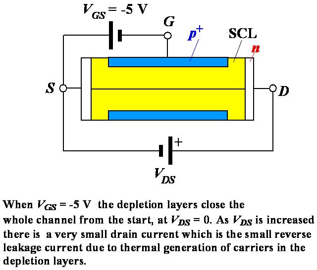
36 BEYOND PINCH-OF, WITH VE V GS, I DS IS WHERE R AP (V GS ) IS THE EFFECTIVE RESISTANCE OF THE CONDUCTING N-CHANNEL FROM A TO P, WHICH DEPENDS ON CHANNEL THICKNESS AND HENCE V GS. WHEN V GS = -V P = -5V WITH V DS = 0, THE TWO DEPLETION LAYERS TOUCH OVER THE ENTIRE CHANNEL LENGTH AND THE WHOLE CHANNEL IS CLOSED. THE CHANNEL SAID TO BE OFF.
37
38
39 THERE IS A CONVENIENT RELATIONSHIP BETWEEN I DS AND V GS. BEYOND PINCH-OFF 2 I DS I DSS 1 V V GS GS ( off ) WHERE I DSS IS DRAIN CURRENT WHEN V GS = 0 AND V GS(OFF) IS DEFINED AS V P, THAT IS GATE-SOURCE VOLTAGE THAT JUST PINCHES OFF THE CHANNEL. THE PINCH OFF VOLTAGE V P HERE IS A +VE QUANTITY BECAUSE IT WAS INTRODUCED THROUGH V DS(SAT). V GS(OFF) HOWEVER IS NEGATIVE, -V P.
40
41
42 I-V CHARACTERISTICS
43 I-V CHARACTERISTICS
44 JFET: I-V CHARACTERISTICS
45 THE TRANSCONDUCTANCE CURVE THE PROCESS FOR PLOTTING TRANSCONDUCTANCE CURVE FOR A GIVEN JFET: PLOT A POINT THAT CORRESPONDS TO VALUE OF V GS(OFF). PLOT A POIT THAT CORRESPONDS TO VALUE OF I DSS. SELECT 3 OR MORE VALUES OF V GS BETWEEN 0 V AND V GS(OFF). FOR VALUE OF V GS, DETERMINE THE CORRESPONDING VALUE OF I D FROM PLOT THE POINT FROM (3) AND CONNECT ALL THE PLOTTED POINT WITH A SMOOTH CURVE.
46 DEVICE STRUCTURE OF MOSFET (N-TYPE) Source(S) Oxide (SiO 2 ) Gate(G) Metal Drain(D) n + Channel area n + p-type Semiconductor Substrate (Body) Body(B) For normal operation, it is needed to create a conducting channel between Source and Drain 2014/9/30 SJTU J. Chen 46
 L = 0.1 to 3 mm W = 0.")

47 DEVICE STRUCTURE OF MOSFET (N-TYPE) L = 0.1 to 3 mm W = 0.2 to 100 mm T ox = 2 to 50 nm Cross-section view 2014/9/30 SJTU J. Chen 47


48 DRAIN CURRENT UNDER PINCH OFF The electrons pass through the pinch off area at very high speed so as the current continuity holds, similar to the water flow at the Yangtze Gorges Pinched-off channel 2014/9/30 SJTU J. Chen 48
49 DRAIN CURRENT CONTROLLED BY V GS V GS CREATES THE CHANNEL. INCREASING V GS WILL INCREASE THE CONDUCTANCE OF THE CHANNEL. AT SATURATION REGION ONLY THE V GS CONTROLS THE DRAIN CURRENT. AT SUBTHRESHOLD REGION, DRAIN CURRENT HAS THE EXPONENTIAL RELATIONSHIP WITH V GS 49
50 P CHANNEL DEVICE TWO REASONS FOR READERS TO BE FAMILIAR WITH P CHANNEL DEVICE Existence in discrete-circuit. More important is the utilization of complementary MOS or CMOS circuits. 2014/9/30 SJTU J. Chen 50
 The i D v DS characteristics for a device with k n (W/L) = 1.0 ma/v 2.")
51 51 OUTPUT CHARACTERISTIC CURVES OF NMOS (a) An n-channel enhancementtype MOSFET with v GS and v DS applied and with the normal directions of current flow indicated. (b) The i D v DS characteristics for a device with k n (W/L) = 1.0 ma/v 2.
52 OUTPUT CHARACTERISTIC CURVES OF NMOS Three distinct region Cutoff region Triode region Saturation region Characteristic equations Circuit model 2014/9/30 SJTU J. Chen 52
53 53 CUTOFF REGION Biased voltage v V GS t The transistor is turned off. i D 0 Operating in cutoff region as a switch.
54 54 TRIODE REGION Biased voltage v v GS DS V v t GS V t The channel depth changes from uniform to tapered shape. Drain current is controlled not only by v DS but also by v GS i D k k n n W ' L W ' L ( v ( v GS GS V ) v t t V ) v DS DS 1 2 v 2 DS process transconductance parameter
55 55 CHANNEL LENGTH MODULATION The MOSFET parameter V A depends on the process technology and, for a given process, is proportional to the channel length L.

56 THE DEPLETION-TYPE MOSFET PHYSICAL STRUCTURE THE STRUCTURE OF DEPLETION-TYPE MOSFET IS SIMILAR TO THAT OF ENHANCEMENT-TYPE MOSFET WITH ONE IMPORTANT DIFFERENCE: THE DEPLETION-TYPE MOSFET HAS A PHYSICALLY IMPLANTED CHANNEL There is no need to induce a channel The depletion MOSFET can be operated at both enhancement mode and depletion mode 56
57 57 CIRCUIT SYMBOL FOR THE N-CHANNEL DEPLETION-MOS Circuit symbol for the n- channel depletion-type MOSFET Simplified circuit symbol applicable for the case the substrate (B) is connected to the source (S).
58 58 CHARACTERISTIC CURVES Expression of characteristic equation i D W k ' ( v L n GS t ) Drain current with I DSS W L kn' Vt v GS V 0 the i D v GS characteristic in saturation
59 59 THE I D V GS CHARACTERISTIC IN SATURATION Sketches of the i D v GS characteristics for MOSFETs of enhancement and depletion types The characteristic curves intersect the v GS axis at V t.

60 THE OUTPUT CHARACTERISTIC CURVES 60
 via a thin insulating layer of SiO 2 The n-doped material lies on a p-doped substrate that may have an additional terminal connection called")
61 Depletion Mode MOSFET Construction The Drain (D) and Source (S) leads connect to the to n-doped regions These N-doped regions are connected via an n-channel This n-channel is connected to the Gate (G) via a thin insulating layer of SiO 2 The n-doped material lies on a p-doped substrate that may have an additional terminal connection called SS
62 OPERASI DASAR A D-MOSFET may be biased to operate in two modes: the Depletion mode or the Enhancement mode
63 D-MOSFET DEPLETION MODE OPERATION 63 The transfer characteristics are similar to the JFET In Depletion Mode operation: When VGS = 0V, ID = IDSS When VGS < 0V, ID < IDSS When VGS > 0V, ID > IDSS The formula used to plot the Transfer Curve, is: I D = I DSS 1 - V V GS P 2
64 64 D-MOSFET ENHANCEMENT MODE OPERATION Enhancement Mode operation In this mode, the transistor operates with V GS > 0V, and I D increases above I DSS Shockley s equation, the formula used to plot the Transfer Curve, still applies but VGS is positive: 2 V GS I D = I DSS 1 - VP
65 p-channel Depletion Mode MOSFET The p-channel Depletion mode MOSFET is similar to the n-channel except that the voltage polarities and current directions are reversed
66 Basic Operation The Enhancement mode MOSFET only operates in the enhancement mode. VGS is always positive IDSS = 0 when VGS < VT As VGS increases above VT, ID increases If VGS is kept constant and VDS is increased, then ID saturates (IDSS) The saturation level, VDSsat is reached.
67 TRANSFER CURVE ID(on) k= To determine ID given VGS: 2 I D = k (V GS - V T) (V 2 GS(ON) - V T ) where VT = threshold voltage or voltage at which the MOSFET turns on. k = constant found in the specification sheet The PSpice determination of k is based on the geometry of the device: W KP k = where KP = μnc L 2 OX
68 P-CHANNEL ENHANCEMENT MODE MOSFETS The p-channel Enhancement mode MOSFET is similar to the n-channel except that the voltage polarities and current directions are reversed.
69 69 Tabel Rangkuman JFET D-MOSFET E-MOSFET
EDC UNIT IV- Transistor and FET JFET Characteristics EDC Lesson 4- ", Raj Kamal, 1
 EDC UNIT IV- Transistor and FET Characteristics Lesson-10: JFET Characteristics Qualitative Discussion 2008 EDC Lesson 4- ", Raj Kamal, 1 n-junction FET and p-jfet Symbols D D + D G + V DS V DS V GS S
EDC UNIT IV- Transistor and FET Characteristics EDC Lesson 9- ", Raj Kamal, 1
 EDC UNIT IV- Transistor and FET Characteristics Lesson-9: JFET and Construction of JFET 2008 EDC Lesson 9- ", Raj Kamal, 1 1. Transistor 2008 EDC Lesson 9- ", Raj Kamal, 2 Transistor Definition The transferred-resistance
FIELD EFFECT TRANSISTORS MADE BY : GROUP (13)/PM
/PM") FIELD EFFECT TRANSISTORS MADE BY : GROUP (13)/PM THE FIELD EFFECT TRANSISTOR (FET) In 1945, Shockley had an idea for making a solid state device out of semiconductors. He reasoned that a strong electrical
FIELD EFFECT TRANSISTORS MADE BY : GROUP (13)/PM THE FIELD EFFECT TRANSISTOR (FET) In 1945, Shockley had an idea for making a solid state device out of semiconductors. He reasoned that a strong electrical
Field Effect Transistors
 Chapter 5: Field Effect Transistors Slide 1 FET FET s (Field Effect Transistors) are much like BJT s (Bipolar Junction Transistors). Similarities: Amplifiers Switching devices Impedance matching circuits
Three Terminal Devices
 Three Terminal Devices - field effect transistor (FET) - bipolar junction transistor (BJT) - foundation on which modern electronics is built - active devices - devices described completely by considering
Chapter 5: Field Effect Transistors
 Chapter 5: Field Effect Transistors Slide 1 FET FET s (Field Effect Transistors) are much like BJT s (Bipolar Junction Transistors). Similarities: Amplifiers Switching devices Impedance matching circuits
6. Field-Effect Transistor
 6. Outline: Introduction to three types of FET: JFET MOSFET & CMOS MESFET Constructions, Characteristics & Transfer curves of: JFET & MOSFET Introduction The field-effect transistor (FET) is a threeterminal
Field-Effect Transistor (FET) is one of the two major transistors; FET derives its name from its working mechanism;
 is one of the two major transistors; FET derives its name from its working mechanism;") Chapter 3 Field-Effect Transistors (FETs) 3.1 Introduction Field-Effect Transistor (FET) is one of the two major transistors; FET derives its name from its working mechanism; The concept has been known
Chapter 3 Field-Effect Transistors (FETs) 3.1 Introduction Field-Effect Transistor (FET) is one of the two major transistors; FET derives its name from its working mechanism; The concept has been known
UNIT-VI FIELD EFFECT TRANSISTOR. 1. Explain about the Field Effect Transistor and also mention types of FET s.
 UNIT-I FIELD EFFECT TRANSISTOR 1. Explain about the Field Effect Transistor and also mention types of FET s. The Field Effect Transistor, or simply FET however, uses the voltage that is applied to their
Chapter 6: Field-Effect Transistors
 Chapter 6: Field-Effect Transistors Islamic University of Gaza Dr. Talal Skaik MOSFETs MOSFETs have characteristics similar to JFETs and additional characteristics that make then very useful. There are
UNIT 3: FIELD EFFECT TRANSISTORS
 FIELD EFFECT TRANSISTOR: UNIT 3: FIELD EFFECT TRANSISTORS The field effect transistor is a semiconductor device, which depends for its operation on the control of current by an electric field. There are
MEASUREMENT AND INSTRUMENTATION STUDY NOTES UNIT-I
 MEASUREMENT AND INSTRUMENTATION STUDY NOTES The MOSFET The MOSFET Metal Oxide FET UNIT-I As well as the Junction Field Effect Transistor (JFET), there is another type of Field Effect Transistor available
FIELD EFFECT TRANSISTOR (FET) 1. JUNCTION FIELD EFFECT TRANSISTOR (JFET)
 1. JUNCTION FIELD EFFECT TRANSISTOR (JFET)") FIELD EFFECT TRANSISTOR (FET) The field-effect transistor (FET) is a three-terminal device used for a variety of applications that match, to a large extent, those of the BJT transistor. Although there
FIELD EFFECT TRANSISTOR (FET) The field-effect transistor (FET) is a three-terminal device used for a variety of applications that match, to a large extent, those of the BJT transistor. Although there
Q1. Explain the construction and principle of operation of N-Channel and P-Channel Junction Field Effect Transistor (JFET).
.") Q. Explain the construction and principle of operation of N-Channel and P-Channel Junction Field Effect Transistor (JFET). Answer: N-Channel Junction Field Effect Transistor (JFET) Construction: Drain(D)
Q. Explain the construction and principle of operation of N-Channel and P-Channel Junction Field Effect Transistor (JFET). Answer: N-Channel Junction Field Effect Transistor (JFET) Construction: Drain(D)
Chapter 6: Field-Effect Transistors
 Chapter 6: Field-Effect Transistors FETs vs. BJTs Similarities: Amplifiers Switching devices Impedance matching circuits Differences: FETs are voltage controlled devices. BJTs are current controlled devices.
KOM2751 Analog Electronics :: Dr. Muharrem Mercimek :: YTU - Control and Automation Dept. 1 6 FIELD-EFFECT TRANSISTORS
 KOM2751 Analog Electronics :: Dr. Muharrem Mercimek :: YTU - Control and Automation Dept. 1 6 FIELD-EFFECT TRANSISTORS Most of the content is from the textbook: Electronic devices and circuit theory, Robert
Digital Electronics. By: FARHAD FARADJI, Ph.D. Assistant Professor, Electrical and Computer Engineering, K. N. Toosi University of Technology
 K. N. Toosi University of Technology Chapter 7. Field-Effect Transistors By: FARHAD FARADJI, Ph.D. Assistant Professor, Electrical and Computer Engineering, K. N. Toosi University of Technology http://wp.kntu.ac.ir/faradji/digitalelectronics.htm
MODULE-2: Field Effect Transistors (FET)
") FORMAT-1B Definition: MODULE-2: Field Effect Transistors (FET) FET is a three terminal electronic device used for variety of applications that match with BJT. In FET, an electric field is established by
FORMAT-1B Definition: MODULE-2: Field Effect Transistors (FET) FET is a three terminal electronic device used for variety of applications that match with BJT. In FET, an electric field is established by
Prof. Paolo Colantonio a.a
 Prof. Paolo Colantonio a.a. 20 2 Field effect transistors (FETs) are probably the simplest form of transistor, widely used in both analogue and digital applications They are characterised by a very high
Depletion-mode operation ( 공핍형 ): Using an input gate voltage to effectively decrease the channel size of an FET
: Using an input gate voltage to effectively decrease the channel size of an FET") Ch. 13 MOSFET Metal-Oxide-Semiconductor Field-Effect Transistor : I D D-mode E-mode V g The gate oxide is made of dielectric SiO 2 with e = 3.9 Depletion-mode operation ( 공핍형 ): Using an input gate voltage
Ch. 13 MOSFET Metal-Oxide-Semiconductor Field-Effect Transistor : I D D-mode E-mode V g The gate oxide is made of dielectric SiO 2 with e = 3.9 Depletion-mode operation ( 공핍형 ): Using an input gate voltage
FIELD EFFECT TRANSISTORS
 FIELD EFFECT TRANSISTORS Module 5 Introduction Symbol Features: 1. Voltage is applied across gate and source terminals. This voltage controls the drain current. Hence FET is a voltage controlled device.
EIE209 Basic Electronics. Transistor Devices. Contents BJT and FET Characteristics Operations. Prof. C.K. Tse: T ransistor devices
 EIE209 Basic Electronics Transistor Devices Contents BJT and FET Characteristics Operations 1 What is a transistor? Three-terminal device whose voltage-current relationship is controlled by a third voltage
Unit III FET and its Applications. 2 Marks Questions and Answers
 Unit III FET and its Applications 2 Marks Questions and Answers 1. Why do you call FET as field effect transistor? The name field effect is derived from the fact that the current is controlled by an electric
FET(Field Effect Transistor)
") Field Effect Transistor: Construction and Characteristic of JFETs. Transfer Characteristic. CS,CD,CG amplifier and analysis of CS amplifier MOSFET (Depletion and Enhancement) Type, Transfer Characteristic,
Field Effect Transistor: Construction and Characteristic of JFETs. Transfer Characteristic. CS,CD,CG amplifier and analysis of CS amplifier MOSFET (Depletion and Enhancement) Type, Transfer Characteristic,
INTRODUCTION: Basic operating principle of a MOSFET:
 INTRODUCTION: Along with the Junction Field Effect Transistor (JFET), there is another type of Field Effect Transistor available whose Gate input is electrically insulated from the main current carrying
CHAPTER 8 FIELD EFFECT TRANSISTOR (FETs)
") CHAPTER 8 FIELD EFFECT TRANSISTOR (FETs) INTRODUCTION - FETs are voltage controlled devices as opposed to BJT which are current controlled. - There are two types of FETs. o Junction FET (JFET) o Metal
CHAPTER 8 FIELD EFFECT TRANSISTOR (FETs) INTRODUCTION - FETs are voltage controlled devices as opposed to BJT which are current controlled. - There are two types of FETs. o Junction FET (JFET) o Metal
IENGINEERS-CONSULTANTS QUESTION BANK SERIES ELECTRONICS ENGINEERING 1 YEAR UPTU ELECTRONICS ENGINEERING EC 101 UNIT 3 (JFET AND MOSFET)
") ELECTRONICS ENGINEERING EC 101 UNIT 3 (JFET AND MOSFET) LONG QUESTIONS (10 MARKS) 1. Draw the construction diagram and explain the working of P-Channel JFET. Also draw the characteristics curve and transfer
ELECTRONICS ENGINEERING EC 101 UNIT 3 (JFET AND MOSFET) LONG QUESTIONS (10 MARKS) 1. Draw the construction diagram and explain the working of P-Channel JFET. Also draw the characteristics curve and transfer
FET. FET (field-effect transistor) JFET. Prepared by Engr. JP Timola Reference: Electronic Devices by Floyd
 JFET. Prepared by Engr. JP Timola Reference: Electronic Devices by Floyd") FET Prepared by Engr. JP Timola Reference: Electronic Devices by Floyd FET (field-effect transistor) unipolar devices - unlike BJTs that use both electron and hole current, they operate only with one type
FET Prepared by Engr. JP Timola Reference: Electronic Devices by Floyd FET (field-effect transistor) unipolar devices - unlike BJTs that use both electron and hole current, they operate only with one type
UNIT-1 Bipolar Junction Transistors. Text Book:, Microelectronic Circuits 6 ed., by Sedra and Smith, Oxford Press
 UNIT-1 Bipolar Junction Transistors Text Book:, Microelectronic Circuits 6 ed., by Sedra and Smith, Oxford Press Figure 6.1 A simplified structure of the npn transistor. Microelectronic Circuits, Sixth
EE70 - Intro. Electronics
 EE70 - Intro. Electronics Course website: ~/classes/ee70/fall05 Today s class agenda (November 28, 2005) review Serial/parallel resonant circuits Diode Field Effect Transistor (FET) f 0 = Qs = Qs = 1 2π
Electronic Circuits. Junction Field-effect Transistors. Dr. Manar Mohaisen Office: F208 Department of EECE
 Electronic Circuits Junction Field-effect Transistors Dr. Manar Mohaisen Office: F208 Email: manar.subhi@kut.ac.kr Department of EECE Review of the Precedent Lecture Explain the Operation Class A Power
Lecture-45. MOS Field-Effect-Transistors Threshold voltage
 Lecture-45 MOS Field-Effect-Transistors 7.4. Threshold voltage In this section we summarize the calculation of the threshold voltage and discuss the dependence of the threshold voltage on the bias applied
I E I C since I B is very small
 Figure 2: Symbols and nomenclature of a (a) npn and (b) pnp transistor. The BJT consists of three regions, emitter, base, and collector. The emitter and collector are usually of one type of doping, while
Basic Electronics Prof. Dr. Chitralekha Mahanta Department of Electronics and Communication Engineering Indian Institute of Technology, Guwahati
 Basic Electronics Prof. Dr. Chitralekha Mahanta Department of Electronics and Communication Engineering Indian Institute of Technology, Guwahati Module: 3 Field Effect Transistors Lecture-7 High Frequency
Introduction to MOSFET MOSFET (Metal Oxide Semiconductor Field Effect Transistor)
") Microelectronic Circuits Introduction to MOSFET MOSFET (Metal Oxide Semiconductor Field Effect Transistor) Slide 1 MOSFET Construction MOSFET (Metal Oxide Semiconductor Field Effect Transistor) Slide 2
Microelectronic Circuits Introduction to MOSFET MOSFET (Metal Oxide Semiconductor Field Effect Transistor) Slide 1 MOSFET Construction MOSFET (Metal Oxide Semiconductor Field Effect Transistor) Slide 2
Field Effect Transistors
 Field Effect Transistors LECTURE NO. - 41 Field Effect Transistors www.mycsvtunotes.in JFET MOSFET CMOS Field Effect transistors - FETs First, why are we using still another transistor? BJTs had a small
4.1 Device Structure and Physical Operation
 10/12/2004 4_1 Device Structure and Physical Operation blank.doc 1/2 4.1 Device Structure and Physical Operation Reading Assignment: pp. 235-248 Chapter 4 covers Field Effect Transistors ( ) Specifically,
EE 5611 Introduction to Microelectronic Technologies Fall Thursday, September 04, 2014 Lecture 02
 EE 5611 Introduction to Microelectronic Technologies Fall 2014 Thursday, September 04, 2014 Lecture 02 1 Lecture Outline Review on semiconductor materials Review on microelectronic devices Example of microelectronic
Laboratory #5 BJT Basics and MOSFET Basics
 Laboratory #5 BJT Basics and MOSFET Basics I. Objectives 1. Understand the physical structure of BJTs and MOSFETs. 2. Learn to measure I-V characteristics of BJTs and MOSFETs. II. Components and Instruments
Summary. Electronics II Lecture 5(b): Metal-Oxide Si FET MOSFET. A/Lectr. Khalid Shakir Dept. Of Electrical Engineering
: Metal-Oxide Si FET MOSFET. A/Lectr. Khalid Shakir Dept. Of Electrical Engineering") Summary Electronics II Lecture 5(b): Metal-Oxide Si FET MOSFET A/Lectr. Khalid Shakir Dept. Of Electrical Engineering College of Engineering Maysan University Page 1-21 Summary The MOSFET The metal oxide
Summary Electronics II Lecture 5(b): Metal-Oxide Si FET MOSFET A/Lectr. Khalid Shakir Dept. Of Electrical Engineering College of Engineering Maysan University Page 1-21 Summary The MOSFET The metal oxide
COLLECTOR DRAIN BASE GATE EMITTER. Applying a voltage to the Gate connection allows current to flow between the Drain and Source connections.
 MOSFETS Although the base current in a transistor is usually small (< 0.1 ma), some input devices (e.g. a crystal microphone) may be limited in their output. In order to overcome this, a Field Effect Transistor
UNIVERSITY OF CALIFORNIA AT BERKELEY College of Engineering Department of Electrical Engineering and Computer Sciences.
 UNIVERSITY OF CALIFORNIA AT BERKELEY College of Engineering Department of Electrical Engineering and Computer Sciences Discussion #9 EE 05 Spring 2008 Prof. u MOSFETs The standard MOSFET structure is shown
(Refer Slide Time: 02:05)
") Electronics for Analog Signal Processing - I Prof. K. Radhakrishna Rao Department of Electrical Engineering Indian Institute of Technology Madras Lecture 27 Construction of a MOSFET (Refer Slide Time:
Electronics for Analog Signal Processing - I Prof. K. Radhakrishna Rao Department of Electrical Engineering Indian Institute of Technology Madras Lecture 27 Construction of a MOSFET (Refer Slide Time:
Analog Electronics. Electronic Devices, 9th edition Thomas L. Floyd Pearson Education. Upper Saddle River, NJ, All rights reserved.
 Analog Electronics BJT Structure The BJT has three regions called the emitter, base, and collector. Between the regions are junctions as indicated. The base is a thin lightly doped region compared to the
UNIT 3 Transistors JFET
 UNIT 3 Transistors JFET Mosfet Definition of BJT A bipolar junction transistor is a three terminal semiconductor device consisting of two p-n junctions which is able to amplify or magnify a signal. It
PESIT Bangalore South Campus
 INTERNAL ASSESSMENT TEST 2 Date : 19/09/2016 Max Marks: 40 Subject & Code : Analog and Digital Electronics (15CS32) Section: III A and B Name of faculty: Deepti.C Time : 8:30 am-10:00 am Note: Answer five
MOSFET Terminals. The voltage applied to the GATE terminal determines whether current can flow between the SOURCE & DRAIN terminals.
 MOSFET Terminals The voltage applied to the GATE terminal determines whether current can flow between the SOURCE & DRAIN terminals. For an n-channel MOSFET, the SOURCE is biased at a lower potential (often
Field Effect Transistors (npn)
") Field Effect Transistors (npn) gate drain source FET 3 terminal device channel e - current from source to drain controlled by the electric field generated by the gate base collector emitter BJT 3 terminal
Field Effect Transistors (npn) gate drain source FET 3 terminal device channel e - current from source to drain controlled by the electric field generated by the gate base collector emitter BJT 3 terminal
Lecture 14. Field Effect Transistor (FET) Sunday 26/11/2017 FET 1-1
 Sunday 26/11/2017 FET 1-1") Lecture 14 Field Effect Transistor (FET) Sunday 26/11/2017 FET 1-1 Outline Introduction to FET transistors Types of FET Transistors Junction Field Effect Transistor (JFET) Characteristics Construction
Lecture 14 Field Effect Transistor (FET) Sunday 26/11/2017 FET 1-1 Outline Introduction to FET transistors Types of FET Transistors Junction Field Effect Transistor (JFET) Characteristics Construction
Chapter 8. Field Effect Transistor
 Chapter 8. Field Effect Transistor Field Effect Transistor: The field effect transistor is a semiconductor device, which depends for its operation on the control of current by an electric field. There
Electronic Circuits II - Revision
 Electronic Circuits II - Revision -1 / 16 - T & F # 1 A bypass capacitor in a CE amplifier decreases the voltage gain. 2 If RC in a CE amplifier is increased, the voltage gain is reduced. 3 4 5 The load
Field Effect Transistor (FET) FET 1-1
 FET 1-1") Field Effect Transistor (FET) FET 1-1 Outline MOSFET transistors ntroduction to MOSFET MOSFET Types epletion-type MOSFET Characteristics Biasing Circuits and Examples Comparison between JFET and epletion-type
Field Effect Transistor (FET) FET 1-1 Outline MOSFET transistors ntroduction to MOSFET MOSFET Types epletion-type MOSFET Characteristics Biasing Circuits and Examples Comparison between JFET and epletion-type
Field-Effect Transistor
 Philadelphia University Faculty of Engineering Communication and Electronics Engineering Field-Effect Transistor Introduction FETs (Field-Effect Transistors) are much like BJTs (Bipolar Junction Transistors).
Solid State Device Fundamentals
 Solid State Device Fundamentals 4.4. Field Effect Transistor (MOSFET) ENS 463 Lecture Course by Alexander M. Zaitsev alexander.zaitsev@csi.cuny.edu Tel: 718 982 2812 4N101b 1 Field-effect transistor (FET)
Lecture 17. Field Effect Transistor (FET) FET 1-1
 FET 1-1") Lecture 17 Field Effect Transistor (FET) FET 1-1 Outline ntroduction to FET transistors Comparison with BJT transistors FET Types Construction and Operation of FET Characteristics Of FET Examples FET 1-2
Lecture 17 Field Effect Transistor (FET) FET 1-1 Outline ntroduction to FET transistors Comparison with BJT transistors FET Types Construction and Operation of FET Characteristics Of FET Examples FET 1-2
8. Characteristics of Field Effect Transistor (MOSFET)
") 1 8. Characteristics of Field Effect Transistor (MOSFET) 8.1. Objectives The purpose of this experiment is to measure input and output characteristics of n-channel and p- channel field effect transistors
1 8. Characteristics of Field Effect Transistor (MOSFET) 8.1. Objectives The purpose of this experiment is to measure input and output characteristics of n-channel and p- channel field effect transistors
Lecture 4. MOS transistor theory
 Lecture 4 MOS transistor theory 1.7 Introduction: A MOS transistor is a majority-carrier device, in which the current in a conducting channel between the source and the drain is modulated by a voltage
THE METAL-SEMICONDUCTOR CONTACT
 THE METAL-SEMICONDUCTOR CONTACT PROBLEM 1 To calculate the theoretical barrier height, built-in potential barrier, and maximum electric field in a metal-semiconductor diode for zero applied bias. Consider
MOSFET & IC Basics - GATE Problems (Part - I)
") MOSFET & IC Basics - GATE Problems (Part - I) 1. Channel current is reduced on application of a more positive voltage to the GATE of the depletion mode n channel MOSFET. (True/False) [GATE 1994: 1 Mark]
MOSFET & IC Basics - GATE Problems (Part - I) 1. Channel current is reduced on application of a more positive voltage to the GATE of the depletion mode n channel MOSFET. (True/False) [GATE 1994: 1 Mark]
Lecture 15. Field Effect Transistor (FET) Wednesday 29/11/2017 MOSFET 1-1
 Wednesday 29/11/2017 MOSFET 1-1") Lecture 15 Field Effect Transistor (FET) Wednesday 29/11/2017 MOSFET 1-1 Outline MOSFET transistors Introduction to MOSFET MOSFET Types epletion-type MOSFET Characteristics Comparison between JFET and
Lecture 15 Field Effect Transistor (FET) Wednesday 29/11/2017 MOSFET 1-1 Outline MOSFET transistors Introduction to MOSFET MOSFET Types epletion-type MOSFET Characteristics Comparison between JFET and
MOS Field-Effect Transistors (MOSFETs)
") 6 MOS Field-Effect Transistors (MOSFETs) A three-terminal device that uses the voltages of the two terminals to control the current flowing in the third terminal. The basis for amplifier design. The basis
6 MOS Field-Effect Transistors (MOSFETs) A three-terminal device that uses the voltages of the two terminals to control the current flowing in the third terminal. The basis for amplifier design. The basis
ITT Technical Institute. ET215 Devices 1. Unit 7 Chapter 4, Sections
 ITT Technical Institute ET215 Devices 1 Unit 7 Chapter 4, Sections 4.1 4.3 Chapter 4 Section 4.1 Structure of Field-Effect Transistors Recall that the BJT is a current-controlling device; the field-effect
Department of Electrical Engineering IIT Madras
 Department of Electrical Engineering IIT Madras Sample Questions on Semiconductor Devices EE3 applicants who are interested to pursue their research in microelectronics devices area (fabrication and/or
Solid State Devices- Part- II. Module- IV
 Solid State Devices- Part- II Module- IV MOS Capacitor Two terminal MOS device MOS = Metal- Oxide- Semiconductor MOS capacitor - the heart of the MOSFET The MOS capacitor is used to induce charge at the
Lecture Integrated circuits era
 Lecture 1 1.1 Integrated circuits era Transistor was first invented by William.B.Shockley, Walter Brattain and John Bardeen of Bell laboratories. In 1961, first IC was introduced. Levels of Integration:-
Semiconductor Physics and Devices
 Metal-Semiconductor and Semiconductor Heterojunctions The Metal-Oxide-Semiconductor Field-Effect Transistor (MOSFET) is one of two major types of transistors. The MOSFET is used in digital circuit, because
Student Lecture by: Giangiacomo Groppi Joel Cassell Pierre Berthelot September 28 th 2004
 Student Lecture by: Giangiacomo Groppi Joel Cassell Pierre Berthelot September 28 th 2004 Lecture outline Historical introduction Semiconductor devices overview Bipolar Junction Transistor (BJT) Field
THE JFET. Script. Discuss the JFET and how it differs from the BJT. Describe the basic structure of n-channel and p -channel JFETs
 Course: B.Sc. Applied Physical Science (Computer Science) Year & Sem.: Ist Year, Sem - IInd Subject: Electronics Paper No.: V Paper Title: Analog Circuits Lecture No.: 12 Lecture Title: Analog Circuits
KOREA UNIVERSITY. Photonics Laboratory. Ch 15. Field effect Introduction-The J-FET and MESFET
 Ch 15. Field effect Introduction-The J-FET and MESFET : (a) The device worked on the principle that a voltage applied to the metallic plate modulated the conductance of the underlying semiconductor, which
Field-Effect Transistor
 Module: Electronics Module Number: 610/6501- Philadelphia University Faculty of Engineering Communication and Electronics Engineering Field-Effect Transistor ntroduction FETs (Field-Effect Transistors)
Field - Effect Transistor
 Page 1 of 6 Field - Effect Transistor Aim :- To draw and study the out put and transfer characteristics of the given FET and to determine its parameters. Apparatus :- FET, two variable power supplies,
ITT Technical Institute. ET215 Devices 1. Unit 8 Chapter 4, Sections
 ITT Technical Institute ET215 Devices 1 Unit 8 Chapter 4, Sections 4.4 4.5 Chapter 4 Section 4.4 MOSFET Characteristics A Metal-Oxide semiconductor field-effect transistor is the other major category of
Difference between BJTs and FETs. Junction Field Effect Transistors (JFET)
") Difference between BJTs and FETs Transistors can be categorized according to their structure, and two of the more commonly known transistor structures, are the BJT and FET. The comparison between BJTs
Difference between BJTs and FETs Transistors can be categorized according to their structure, and two of the more commonly known transistor structures, are the BJT and FET. The comparison between BJTs
97.398*, Physical Electronics, Lecture 21. MOSFET Operation
 97.398*, Physical Electronics, Lecture 21 MOSFET Operation Lecture Outline Last lecture examined the MOSFET structure and required processing steps Now move on to basic MOSFET operation, some of which
EE301 Electronics I , Fall
 EE301 Electronics I 2018-2019, Fall 1. Introduction to Microelectronics (1 Week/3 Hrs.) Introduction, Historical Background, Basic Consepts 2. Rewiev of Semiconductors (1 Week/3 Hrs.) Semiconductor materials
Electronics I. Last Time
 (Rev. 1.0) Electronics I Lecture 28 Introduction to Field Effect Transistors (FET s) Muhammad Tilal Department of Electrical Engineering CIIT Attock Campus The logo and is the property of CIIT, Pakistan
IFB270 Advanced Electronic Circuits
 IFB270 Advanced Electronic Circuits Chapter 9: FET amplifiers and switching circuits Prof. Manar Mohaisen Department of EEC Engineering Review of the Precedent Lecture Review of basic electronic devices
(a) Current-controlled and (b) voltage-controlled amplifiers.
 Current-controlled and (b) voltage-controlled amplifiers.") Fig. 6.1 (a) Current-controlled and (b) voltage-controlled amplifiers. Fig. 6.2 Drs. Ian Munro Ross (front) and G. C. Dacey jointly developed an experimental procedure for measuring the characteristics
Fig. 6.1 (a) Current-controlled and (b) voltage-controlled amplifiers. Fig. 6.2 Drs. Ian Munro Ross (front) and G. C. Dacey jointly developed an experimental procedure for measuring the characteristics
Design cycle for MEMS
 Design cycle for MEMS Design cycle for ICs IC Process Selection nmos CMOS BiCMOS ECL for logic for I/O and driver circuit for critical high speed parts of the system The Real Estate of a Wafer MOS Transistor
Analogue Electronics
 Università degli Studi di Roma Tor Vergata Dipartimento di Ingegneria Elettronica Analogue Electronics Paolo Colantonio A.A. 2015-16 Field-effect transistors Field-effect transistors (FETs) are probably
L MOSFETS, IDENTIFICATION, CURVES. PAGE 1. I. Review of JFET (DRAW symbol for n-channel type, with grounded source)
") L.107.4 MOSFETS, IDENTIFICATION, CURVES. PAGE 1 I. Review of JFET (DRAW symbol for n-channel type, with grounded source) 1. "normally on" device A. current from source to drain when V G = 0 no need to
L.107.4 MOSFETS, IDENTIFICATION, CURVES. PAGE 1 I. Review of JFET (DRAW symbol for n-channel type, with grounded source) 1. "normally on" device A. current from source to drain when V G = 0 no need to
Lecture (03) The JFET
 The JFET") Lecture (03) The JFET By: Dr. Ahmed ElShafee ١ JFET Basic Structure Figure shows the basic structure of an n channel JFET (junction field effect transistor). Wire leads are connected to each end of the
Lecture (03) The JFET By: Dr. Ahmed ElShafee ١ JFET Basic Structure Figure shows the basic structure of an n channel JFET (junction field effect transistor). Wire leads are connected to each end of the
NAME: Last First Signature
 UNIVERSITY OF CALIFORNIA, BERKELEY College of Engineering Department of Electrical Engineering and Computer Sciences EE 130: IC Devices Spring 2003 FINAL EXAMINATION NAME: Last First Signature STUDENT
INTRODUCTION TO MOS TECHNOLOGY
 INTRODUCTION TO MOS TECHNOLOGY 1. The MOS transistor The most basic element in the design of a large scale integrated circuit is the transistor. For the processes we will discuss, the type of transistor
MOS TRANSISTOR THEORY
 MOS TRANSISTOR THEORY Introduction A MOS transistor is a majority-carrier device, in which the current in a conducting channel between the source and the drain is modulated by a voltage applied to the
Lecture 16: MOS Transistor models: Linear models, SPICE models. Context. In the last lecture, we discussed the MOS transistor, and
 Lecture 16: MOS Transistor models: Linear models, SPICE models Context In the last lecture, we discussed the MOS transistor, and added a correction due to the changing depletion region, called the body
Field Effect Transistors (FET s) University of Connecticut 136
 University of Connecticut 136") Field Effect Transistors (FET s) University of Connecticut 136 Field Effect Transistors (FET s) FET s are classified three ways: by conduction type n-channel - conduction by electrons p-channel - conduction
Field Effect Transistors (FET s) University of Connecticut 136 Field Effect Transistors (FET s) FET s are classified three ways: by conduction type n-channel - conduction by electrons p-channel - conduction
Lecture 13. Metal Oxide Semiconductor Field Effect Transistor (MOSFET) MOSFET 1-1
 MOSFET 1-1") Lecture 13 Metal Oxide Semiconductor Field Effect Transistor (MOSFET) MOSFET 1-1 Outline Continue MOSFET Qualitative Operation epletion-type MOSFET Characteristics Biasing Circuits and Examples Enhancement-type
Lecture 13 Metal Oxide Semiconductor Field Effect Transistor (MOSFET) MOSFET 1-1 Outline Continue MOSFET Qualitative Operation epletion-type MOSFET Characteristics Biasing Circuits and Examples Enhancement-type
Sub-Threshold Region Behavior of Long Channel MOSFET
 Sub-threshold Region - So far, we have discussed the MOSFET behavior in linear region and saturation region - Sub-threshold region is refer to region where Vt is less than Vt - Sub-threshold region reflects
Transistor was first invented by William.B.Shockley, Walter Brattain and John Bardeen of Bell Labratories. In 1961, first IC was introduced.
 Unit 1 Basic MOS Technology Transistor was first invented by William.B.Shockley, Walter Brattain and John Bardeen of Bell Labratories. In 1961, first IC was introduced. Levels of Integration:- i) SSI:-
Lecture (10) MOSFET. By: Dr. Ahmed ElShafee. Dr. Ahmed ElShafee, ACU : Fall 2016, Electronic Circuits II
 MOSFET. By: Dr. Ahmed ElShafee. Dr. Ahmed ElShafee, ACU : Fall 2016, Electronic Circuits II") Lecture (10) MOSFET By: Dr. Ahmed ElShafee ١ Dr. Ahmed ElShafee, ACU : Fall 2017, Electronic Circuits II Introduction The MOSFET (metal oxide semiconductor field effect transistor) is another category
Lecture (10) MOSFET By: Dr. Ahmed ElShafee ١ Dr. Ahmed ElShafee, ACU : Fall 2017, Electronic Circuits II Introduction The MOSFET (metal oxide semiconductor field effect transistor) is another category
Questions on JFET: 1) Which of the following component is a unipolar device?
 Which of the following component is a unipolar device?") Questions on JFET: 1) Which of the following component is a unipolar device? a) BJT b) FET c) DJT d) EFT 2) Current Conduction in FET takes place due e) Majority charge carriers only f) Minority charge
Questions on JFET: 1) Which of the following component is a unipolar device? a) BJT b) FET c) DJT d) EFT 2) Current Conduction in FET takes place due e) Majority charge carriers only f) Minority charge
Conduction Characteristics of MOS Transistors (for fixed Vds)! Topic 2. Basic MOS theory & SPICE simulation. MOS Transistor
! Topic 2. Basic MOS theory & SPICE simulation. MOS Transistor") Conduction Characteristics of MOS Transistors (for fixed Vds)! Topic 2 Basic MOS theory & SPICE simulation Peter Cheung Department of Electrical & Electronic Engineering Imperial College London (Weste&Harris,
Conduction Characteristics of MOS Transistors (for fixed Vds)! Topic 2 Basic MOS theory & SPICE simulation Peter Cheung Department of Electrical & Electronic Engineering Imperial College London (Weste&Harris,
Topic 2. Basic MOS theory & SPICE simulation
 Topic 2 Basic MOS theory & SPICE simulation Peter Cheung Department of Electrical & Electronic Engineering Imperial College London (Weste&Harris, Ch 2 & 5.1-5.3 Rabaey, Ch 3) URL: www.ee.ic.ac.uk/pcheung/
Conduction Characteristics of MOS Transistors (for fixed Vds) Topic 2. Basic MOS theory & SPICE simulation. MOS Transistor
 Topic 2. Basic MOS theory & SPICE simulation. MOS Transistor") Conduction Characteristics of MOS Transistors (for fixed Vds) Topic 2 Basic MOS theory & SPICE simulation Peter Cheung Department of Electrical & Electronic Engineering Imperial College London (Weste&Harris,
Conduction Characteristics of MOS Transistors (for fixed Vds) Topic 2 Basic MOS theory & SPICE simulation Peter Cheung Department of Electrical & Electronic Engineering Imperial College London (Weste&Harris,
ECE520 VLSI Design. Lecture 2: Basic MOS Physics. Payman Zarkesh-Ha
 ECE520 VLSI Design Lecture 2: Basic MOS Physics Payman Zarkesh-Ha Office: ECE Bldg. 230B Office hours: Wednesday 2:00-3:00PM or by appointment E-mail: pzarkesh@unm.edu Slide: 1 Review of Last Lecture Semiconductor
Transistors. Bipolar Junction transistors Principle of operation Characteristics. Field effect transistors Principle of operation Characteristics
 Transistors ipolar Junction transistors Principle of operation haracteristics Field effect transistors Principle of operation haracteristics ntroduction Radio based on vacuum tubes Fundamental building
55:041 Electronic Circuits
 55:041 Electronic Circuits Mosfet Review Sections of Chapter 3 &4 A. Kruger Mosfet Review, Page-1 Basic Structure of MOS Capacitor Sect. 3.1 Width 1 10-6 m or less Thickness 50 10-9 m or less ` MOS Metal-Oxide-Semiconductor
55:041 Electronic Circuits
 55:041 Electronic Circuits MOSFETs Sections of Chapter 3 &4 A. Kruger MOSFETs, Page-1 Basic Structure of MOS Capacitor Sect. 3.1 Width = 1 10-6 m or less Thickness = 50 10-9 m or less ` MOS Metal-Oxide-Semiconductor
Summary of Lecture Notes on Metal-Oxide-Semiconductor, Field-Effect Transistors (MOSFETs)
") Mani Vaidyanathan 1 Summary of Lecture Notes on Metal-Oxide-Semiconductor, Field-Effect Transistors (MOSFETs) Introduction 1. We began by asking, Why study MOSFETs? The answer is, Because MOSFETs are the
Mani Vaidyanathan 1 Summary of Lecture Notes on Metal-Oxide-Semiconductor, Field-Effect Transistors (MOSFETs) Introduction 1. We began by asking, Why study MOSFETs? The answer is, Because MOSFETs are the