Transmissions Electron Microscopy (TEM)
|
|
|
- Christian Ferguson
- 5 years ago
- Views:
Transcription

1 Transmissions Electron Microscopy (TEM) Basic principles Diffraction Imaging Specimen preparation A.E. Gunnæs MENA3100 V18
2 Electron interaction with the (thin) specimen e - Typical specimen thickness Absorbed electrons EBIC Auger electrons Cathodoluminescence Backscattered electrons Secondary electrons X-rays Specimen Gas Heating Cooling ~ 100 nm or less Elastically scattered electrons Inelastically scattered electrons Transmitted electrons Electrons interacts times stronger with matter than X-rays -need thin samples


")
")


3 perating modes Convergent beam Parallel beam Can be scanned (STEM mode) Spectroscopy and mapping (EDS and EELS) Specimen Example of EDS mapping in STEM mode. Cu 2 (sputtering, 600nm) Ti 2 (ALD, 10 nm) AZ (sputtering, ~200 nm) Quartz (1mm) S. Gorantla STEM: Scanning transmission electron microscopy HAADF: High angular annular dark field EDS: Energy dispersive spectroscopy EELS: Electron energy loss spectroscopy
 Spectroscopy Chemistry and elecronic states (EDS and EELS). Spatial and energy resolution down to the atomic level and ~0.1 ev.")
4 TEM is based on three possible set of techniqes Diffraction From regions down to a few nm (CBED). Imaging With spatial resolution down to the atomic level (HREM and STEM) Spectroscopy Chemistry and elecronic states (EDS and EELS). Spatial and energy resolution down to the atomic level and ~0.1 ev. 200 nm SAD pattern CBED: Convergent beam electron diffraction SAD: Selected area diffraction BF TEM image HREM: High resolution electron microscopy BF: Bright field

5 Imaging and resolution Resolution of the eyes:~ mm Resolution in a visible light microscope: ~200 nm Modern TEMs with Cs correctors have sub Å resolution! A.E. Gunnæs

6 The interesting objects for TEM is local structure and inhomogeneities in specimens Important for material properties Defects Interfaces Cu Precipitates Local atomic structure and composition, HAADF image Zn Electronic structure and chemical bonding S. Gorantla Strain analysis around a dislocation core at the Cu-Zn interface
7 An example of a TEM study: Identification of an unknown phase in a thin film A.E. Gunnæs
8 PowderCell 2.0 Specimen: thin film of BiFe 3 + unknown phase Metal organic compound on Pt Ti 2 Pt BiFe 3 Lim Glue Heat treatment at 350 o C (10 min) to remove organic parts. Process repeated three times before final heat treatment at o C (20 min). (intermetallic phase grown) Si 2 Bi Bi Si Bi Fe Bi Bi Fe Fe 200 nm A.E. Gunnæs BF TEM image of the cross section of the specimen Fe Bi Bi Bi Fe Fe Fe Bi Bi Bi Fe Fe Goal to produce single phase: BiFe 3 with space grupe: R3C and celle dimentions: a= Å c= Å Fe Bi Bi Fe Fe Bi b c a Bi Bi


9 Determination of the Bravais-lattice of an unknown crystalline phase Tilting series around a dens row of reflections in the reciprocal space 0 o 50 nm 19 o A. E. Gunnæs Positions of the reflections in the reciprocal space 25 o 40 o 52 o Courtesy: Dr. Jürgen Thomas, IFW-Dresden, Germany
10 Electron Diffraction in TEM Elastic scattered electrons nly the direction of v is changing. (Bragg scattering) Elastic scattering is due to Coulomb interaction between the incident electrons and the electric charge of the electron clouds and the nucleus. (Rutherford scattering). The elastic scattering is due to the average position of the atoms in the lattice. Reflections satisfying Braggs law: 2dsinθ=nλ Electrons interacts times stronger with matter than X-rays -can detect weak reflections not observed with XRD technique Courtesy: Dr. Jürgen Thomas, IFW-Dresden, Germany


11 6.04 Å Bravais-lattice and cell parameters c b [011] [100] [101] a 100 d = L λ / R From the tilt series we find that the unknown phase has a primitive orthorhombic Bravias-lattice with cell parameters: a= 6,04 Å, b= 7.94 Å og c=8.66 Å 7.94 Å α= β= γ= 90 o
12 Chemical analysis by use of EDS and EELS Ukjent fase BiFe 3 BiFe 2 5 CCD CCD counts counts x 1000 x _1evprc.PICT Nr_2_1evprc.PICT - K Fe - L2,3 BiFe 3 Ukjent fase ev forskyvning, ev pr. 600 kanal Energy 400 Loss 600 (ev) Energy Loss (ev)
13 PowderCell 2.0 Published structure A.G. Tutov og V.N. Markin The x-ray structural analysis of the antiferromagnetic Bi 2 Fe 4 9 and the isotypical combinations Bi 2 Ga 4 9 and Bi 2 Al 4 9 Izvestiya Akademii Nauk SSSR, Neorganicheskie Materialy (1970), 6, Romgruppe: Pbam nr. 55, celleparametre: 7,94 Å, 8,44 Å, 6.01Å Bi x y z Bi 4g 0,176 0,175 0 Fe 4h 0,349 0,333 0,5 Fe 4f 0 0,5 0,244 4g 0,14 0, i 0,385 0,207 0,242 4h 0,133 0,427 0,5 2b 0 0 0,5 Fe Fe Fe Bi Fe Fe Bi Fe Bi Fe Bi Bi Fe Fe Bi Bi Fe Fe Fe b c a Celle parameters found with electron diffraction (a= 6,04 Å, b= 7.94 Å and c=8.66 Å) fits reasonably well with the previously published data for the Bi 2 Fe 4 9 phase. The disagreement in the c-axis may be due to the fact that we have been studying a thin film grown on a crystalline substrate and is not a bulk sample. The conditions for reflections from the space group Pbam is in agreement with observations done with electron diffraction. Conclusion: The unknown phase has been identified as Bi 2 Fe 4 9 with space group Pbam with cell parameters a= 6,04 Å, b= 7.94 Å and c=8.66 Å.

14 A.E. Gunnæs The construction of a TEM

15 A.E. Gunnæs
16 Basic TEM Electron gun Apertures 1. and 2. condenser lenses Sample Vacuum in the column better than 10-6 Pa Sample holder bjective lens Intermediate lenses Projector lens Recording media (Cameras, detectors) Fluorescence screen Similar components as a transmission light microscope


17 The electron source Two types of emission guns: Thermionic emission W or LaB 6 Field emission Cold FEG W Schottky FEG Zr/W Thermionic emission
18 Thermionic guns Filament heated to give thermionic emission -Directly (W) or indirectly (LaB 6 ) Filament negative potential to ground Wehnelt produces a small negative bias -Brings electrons to cross over

19 Field emission gun The principle: The strength of an electric field E is considerably increased at sharp points. E=V/r r W < 0.1 µm, V=1 kv E = V/m Lowers the work-function barrier so that electrons can tunnel out of the tungsten. Surface has to be pristine (no contamination or oxide) Ultra high vacuum condition (Cold FEG) or poorer vacuum if tip is heated ( thermal FE; Zr surface tratments Schottky emitters).
 The point resolution in a TEM is limited by the aberrations of")
20 Resolution (JEL2100F: 0.19 nm) The point resolution in a TEM is limited by the aberrations of the lenses. -Spherical - Chromatic -Astigmatism


21 Electromagnetic lenses A charged particle such as an electron, is deflected by a magnetic field. The direction and magnitude of the force F, on the electron is given by the vector equation: F= -e(v x B)
22 Basic TEM Electron gun Apertures 1. and 2. condenser lenses Sample Vacuum in the column better than 10-6 Pa Sample holder bjective lens Intermediate lenses Projector lens Recording media (Cameras, detectors) Fluorescence screen Similar components as a transmission light microscope
23 c b a 3,8 Å Simplified ray diagram Si Parallel incoming electron beam Sample 1,1 nm PowderCell 2.0 bjective lense Diffraction plane (back focal plane) bjective aperture Image plane Selected area aperture
24 Selected area diffraction Parallel incoming electron beam Specimen with two crystals (red and blue) Diffraction from a single crystal in a polycrystalline sample if the aperture is small enough/crystal large enough. rientation relationships can be determined. ~2% accuracy of lattice parameters bjective lense XRD is much more accurate Diffraction pattern Pattern on the screen Selected area aperture Image plane


25 Electron Diffraction in TEM Amorphous phase Poly crystalline sample Single Crystals Interface between two different phases epitaxially grown The orientation relationship between the phases can be determined with ED. 25


26 Diffraction with large SAD aperture, ring and spot patterns SAD Similarities to XRD
27 Why do we observe many reflections in one diffraction pattern? 2dsinθ B =λ Cu K alpha X-ray: = 150 pm Electrons at 200 kv: = 2.5 pm Courtesy: Dr. Jürgen Thomas, IFW- Dresden, Germany
28 Illustration with the Ewald Sphere The radius of the Ewald sphere is 1/ (=k) Cu K alpha X-ray: = 150 pm => small k Electrons at 200 kv: = 2.5 pm => large k ko k Resiprocal lattice of a crystal
29 ED and form effects The dimensions of the specimen affects the shape of the resiprocal lattice poins Real space Resiprocal space
30 The intensity distribution around each reciprocal lattice point is spread out in the form of spikes directed normal to the specimen. 2d sinθ = nλ λ 200kV = nm Θ~1 o I(k -k)i=(2/λ)sinθ B =g
31 Zone axis and Laue zones Zone axis [uvw] (hkl) uh+vk+wl= 0
32 Indexing diffraction patterns The g vector to a reflection is normal to the corresponding (h k l) plane and IgI=1/d nh nk nl - Measure R i and the angles between the reflections - Calculate d i, i=1,2,3 (=K/R i ) - Compare with tabulated/theoretical calculated d-values of possible phases (h 2 k 2 l 2 ) - Compare R i /R j with tabulated values for cubic structure. - g 1,hkl + g 2,hkl =g 3,hkl (vector sum must be ok) - Perpendicular vectors: g i g j = 0 rientations of corresponding planes in the real space - Zone axis: g i x g j =[HKL] z - All indexed g must satisfy: g [HKL] z =0
33 A.E. Gunnæs TEM imaging with parallell incomming beam

34 Imaging / microscopy Amplitude contrast Phase contrast BiFe 3 Pt Si 2 Ti 2 Glue Si 200 nm The elctron wave can change both its amplitude and phase as it traverses the specimen Give rise to contrast We select imaging conditions so that one of them dominates.
35 Contrast Difference in intensity of to adjacent areas: C ( I 2 I1) I 1 I I 1 The eyes can not see intensity chanes that is less then 5-10%, however, contrast in images can be enhanced digitally. NB! It is correct to talk about strong and week contrast but not bright and dark contrast
36 Use of apertures Condenser aperture: Limits the number of electrons reaching the specimen (reducing the intensity), Affecting the convergent of the electron beam. Selected area aperture: Allows only electrons going through an area on the sample that is limited by the SAD aperture to contribute to the diffraction pattern (SAD pattern). bjective aperture: Allows certain reflections to contribute to the image. Increases the contrast in the image. Bright field imaging (central beam, 000), Dark field imaging (one reflection, g), High resolution Images (several reflections from a zone axis).
 bjective aperture Image plane Selected area")
37 c b a 3,8 Å Simplified ray diagram Si Parallel incoming electron beam Sample 1,1 nm PowderCell 2.0 bjective lense Diffraction plane (back focal plane) bjective aperture Image plane Selected area aperture
 No aperture used")

38 bjective aperture: Contrast enhancement Si Ag and Pb hole glue (light elements) No aperture used Amplitude contrast: Central beam selected Mass-Density contrast and Diffraction contrast A.E. Gunnæs
39 Mass-Density contrast in TEM Incoherent elastic scattering (Rutherford scattering): peaked in the forward direction, t and Z-dependent Areas of greater Z and/or t scatter electrons more strongly (in total). TEM variables that affect the contrast: -The objective aperture size. -The high tension of the TEM. Williams and Carter, TEM, Part 3 Springer 2009

40 Mass-density contrast A.E. Gunnæs
41 bjective aperture: Contrast enhancement Intensity: Dependent on grain orientation Diffraction contrast 50 nm Try to make an illustration to explain why we get this enhanced contrast when only the central beam is selected by the optical aperture.
42 Diffraction contrast Bright field image A.E. Gunnæs
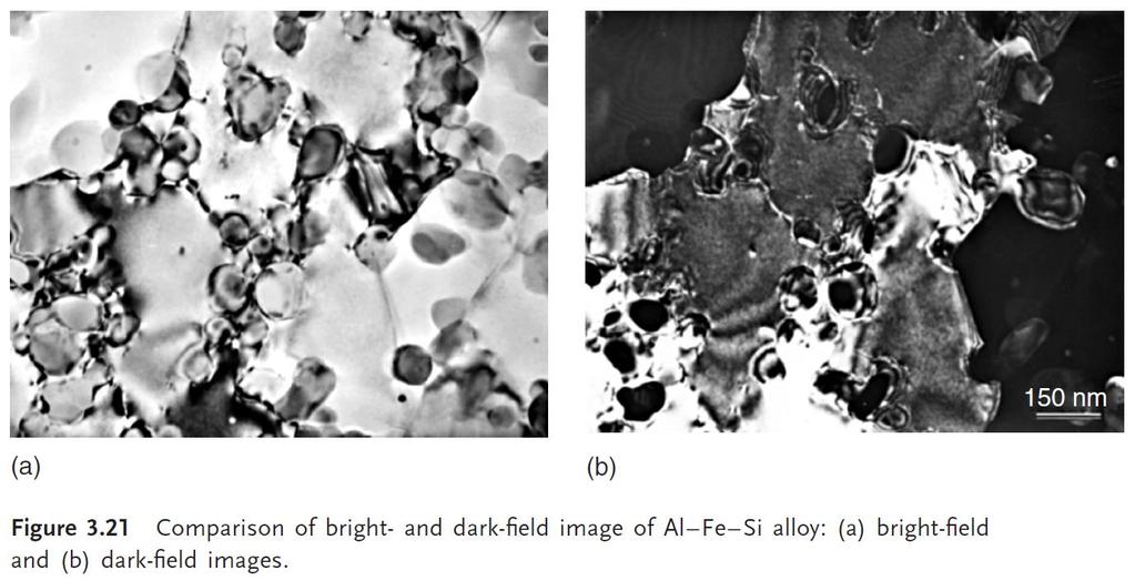
43 Size of objective aperture Bright field (BF), dark field (DF) and High resolution EM (HREM) bjective aperture BF image DF image HREM image Amplitude/Diffraction contrast Phase contrast

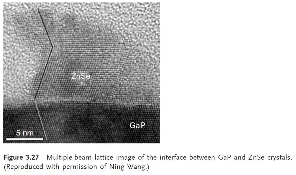
44 Phase contrast: HREM and Moire fringes Long-Wei Yin et al., Materials Letters, 52, p HREM image Interference pattern A Moiré pattern is an interference pattern created, for example, when two grids are overlaid at an angle, or when they have slightly different mesh sizes (rotational and parallel Moire patterns).
45 PART II Transmissions Electron Microscopy (TEM) Basic principles Diffraction Imaging Specimen preparation A.E. Gunnæs MENA3100 V18
46 A.E. Gunnæs Some repetiton.
47 TEM mode with parallel incoming electron beam Specimen Change the strength of the intermediate lens: The diffraction pattern or image of the specimen is magnified
48 TEM mode with parallel incoming electron beam Apertures (No: Blendere) Condenser bject SAD Specimen SAD aperture: used to select an area on the specimen one want diffraction date from (on the second intermediat image and projected).
49 TEM mode with parallel incoming electron beam Apertures (No: Blendere) Condenser bject SAD Specimen bjective aperture: used to select which electron beams will contribute to the image (on the second intermediat image and projected).
50 The objective aperture is used to controls the contrast in the image (enhances contrast). TEM mode with parallel incoming electron beam ne beam: Amplitude contrast (central (BF) or a scattered beam (DF)) Two or more beams: Phase contrast (+ amplitude) (HREM images (zone axis) or Moire) bjective aperture: used to select which electron beams will contribute to the image (on the second intermediat image and projected).
, dark field")
 bjective aperture BF")

51 Size of objective aperture Bright field (BF), dark field (DF) and High resolution EM (HREM) bjective aperture BF image DF image HREM image Amplitude/Diffraction contrast Phase contrast

52 Phase contrast
53 Amplitude contrast Diffraction contrast and Mass-density contrast A TEM image will in most cases show both contrast types
54 Mass-Density contrast in TEM Incoherent elastic scattering (Rutherford scattering): peaked in the forward direction, t and Z-dependent Areas of greater Z and/or t scatter electrons more strongly (in total). Williams and Carter, TEM, Part 3 Springer 2009 TEM variables that affect the contrast: -The objective aperture size. -The high tension of the TEM.
 Bright field image A.E.")
55 Diffraction contrast in the TEM 50 nm The contrast is very sencitive to the specimen orientation. (In contrast to mass-density contrast) Bright field image A.E. Gunnæs

56 Effect of specimen tilt on diffraction contrast
57 Diffraction contrast
58 Where do you see a)mass-density contrast and b) Diffraction contrast? BiFe 3 Pt Ti 2 Glue Si 2 Si 200 nm
59 Crystal defects - Effect of bending - Dislocations - Wedges

.")
60 Bending contours sample bj. lens bj. aperture BF image DF image DF image A.E. Gunnæs Solberg, Jan Ketil & Hansen, Vidar (2001). Innføring i transmisjon elektronmikroskopi

61 Bending contours
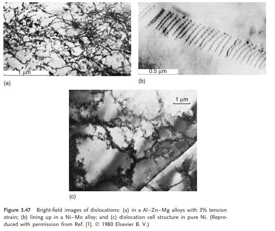
62 Dislocations
63 Double diffraction, extinction thickness Double electron diffraction leads to oscillations in the diffracted intensity with increasing thickness of the sample Incident beam No double diffraction with XRD, kinematical intensities Forbidden reflection may be observed t 0 : Extinction thickness Periodicity of the oscillations t 0 =πv c /λif(hkl)i Wedge shaped TEM sample Diffracted beam Doubly Transmitted diffracted beam beam t 0
64 Simplified kinematical theory for perfect crystals Basis of kinematical theory of electron diffraction for imperfect crystals: t Ψ g (t)= (πi/ξ g ) exp(-2πis g z)dz, 0 Ψ o =1, t: crystal thickess Ψ g (t)= (i/ξ g s g ) exp(-πits g ) sinπs g t Intensity of the scattered beam g (dark field): I g = l Ψ g (t) l 2 = sin 2 πs g t/(ξ g s g ) 2 Intensity of the unscattered beam 0 (bright field): I 0 = 1-I g = 1- l Ψ g (t) l 2 = 1 - sin 2 πs g t/(ξ g s g ) 2
65 Thickness fringes (s g konstant) In the two-beam situation the intensity of the diffracted and direct beam is periodic with thickness (I g =1- I o ) e 000 g I g =1- I o Sample (side view) t Hole Sample (top view) A.E. Gunnæs Intensity of the scattered beam g: I g = l Ψ g (t) l 2 = sin 2 πs g t/(ξ g s g ) 2 MENA3100 V10 Positions with max Intensity in I g


66 Thickness fringes, bright and dark field images Sample Sample BF image DF image A.E. Gunnæs MENA3100 V10
67 Kikuchi lines rigin and use


68 Line pairs in the diffraction plane Need to have a thick specimen region Close to a zone axis Zone axis pattern
69 Need two scattering events 1. Inelastic 2. Elastic 1. -Angular distribution of inelastic scattered electrons falls of rapidly with angle. I=I o cos 2 α
70 Kikuchi pattern. Incoherently and inelastically (ΔE~15-25 ev) scattered electrons give rise to diffuse background in the ED pattern 1.Ineleastic scattering + θb Deficient Excess 2. Bragg scattering event θb 2θB bjective lens Diffraction plane Deficient line 1/d Excess line What will happen if you tilt the specimen?
71 Kikuchi maps Kossel cones -g 000 g I g =I -g Sg<0 Sg=0 g and g Kikuchi lines Parabolas Effect of tilting the specimen
72 TEM specimen preparation
73 What to considder before preparing a TEM specimen Ductile/fragile Bulk/surface/powder Insulating/conducting Heat resistant Single phase/multi phase Etc, etc. What is the objectiv of the TEM work?


74 Specimen preparation for TEM Crushing Cutting saw, diamond pen, ultrasonic drill, ultramicrotomy Mechanical thinning Grinding, dimpling, Tripod polishing Electrochemical thinning Ion milling Coating Replica methods FIB (Focused ion beam) Etc.
75 Grids Several types Different materials (Mo, Cu, Ni ) Support brittle materials Support small particles 3 mm The grid may contribute to the EDS signal.


76 Preparation of self-supporting discs Top view specimens Cutting Ductile material or not? Grinding μm thick polish Cut the 3mm disc Dimple? Final thinning Ion beam milling Electropolishing
77 Cross section TEM sample preparation: Thin films Top view Cut out cylinder Grind down/ dimple Ione beam thinning Cut out slices Cut out a cylinder and glue it in a Cu-tube Grind down and glue on support rings Cross section Glue the interface of interest face to face together with support material or Focused Ion Beam (FIB) Cut a slice of the cylinder and grind it down / dimple Cut off excess material Ione beam thinning A.E. Gunnæs
78 Focused ion beam TEM specimen preparation
Transmissions Electron Microscopy (TEM)
") Transmissions Electron Microscopy (TEM) Basic principles Diffraction Imaging Specimen preparation A.E. Gunnæs MENA3100 V17 TEM is based on three possible set of techniqes Diffraction From regions down
Transmissions Electron Microscopy (TEM) Basic principles Diffraction Imaging Specimen preparation A.E. Gunnæs MENA3100 V17 TEM is based on three possible set of techniqes Diffraction From regions down
Introduction to Transmission Electron Microscopy (Physical Sciences)
") Introduction to Transmission Electron Microscopy (Physical Sciences) Centre for Advanced Microscopy Program 9:30 10:45 Lecture 1 Basics of TEM 10:45 11:00 Morning tea 11:00 12:15 Lecture 2 Diffraction
Introduction to Transmission Electron Microscopy (Physical Sciences) Centre for Advanced Microscopy Program 9:30 10:45 Lecture 1 Basics of TEM 10:45 11:00 Morning tea 11:00 12:15 Lecture 2 Diffraction
NanoSpective, Inc Progress Drive Suite 137 Orlando, Florida
 TEM Techniques Summary The TEM is an analytical instrument in which a thin membrane (typically < 100nm) is placed in the path of an energetic and highly coherent beam of electrons. Typical operating voltages
ELECTRON MICROSCOPY. 13:10 16:00, Oct. 6, 2008 Institute of Physics, Academia Sinica. Tung Hsu
 ELECTRON MICROSCOPY 13:10 16:00, Oct. 6, 2008 Institute of Physics, Academia Sinica Tung Hsu Department of Materials Science and Engineering National Tsing Hua University Hsinchu 300, TAIWAN Tel. 03-5742564
Chapter 4 Imaging Lecture 17
 Chapter 4 Imaging Lecture 17 d (110) Imaging Imaging in the TEM Diffraction Contrast in TEM Image HRTEM (High Resolution Transmission Electron Microscopy) Imaging STEM imaging Imaging in the TEM What is
Chapter 2 Instrumentation for Analytical Electron Microscopy Lecture 7. Chapter 2 CHEM Fall L. Ma
 Chapter 2 Instrumentation for Analytical Electron Microscopy Lecture 7 Outline Electron Sources (Electron Guns) Thermionic: LaB 6 or W Field emission gun: cold or Schottky Lenses Focusing Aberration Probe
Transmission electron Microscopy
 Transmission electron Microscopy Image formation of a concave lens in geometrical optics Some basic features of the transmission electron microscope (TEM) can be understood from by analogy with the operation
ELECTRON MICROSCOPY. 14:10 17:00, Apr. 3, 2007 Department of Physics, National Taiwan University. Tung Hsu
 ELECTRON MICROSCOPY 14:10 17:00, Apr. 3, 2007 Department of Physics, National Taiwan University Tung Hsu Department of Materials Science and Engineering National Tsinghua University Hsinchu 300, TAIWAN
2.Components of an electron microscope. a) vacuum systems, b) electron guns, c) electron optics, d) detectors. Marco Cantoni 021/
 vacuum systems, b) electron guns, c) electron optics, d) detectors. Marco Cantoni 021/") 2.Components of an electron microscope a) vacuum systems, b) electron guns, c) electron optics, d) detectors, 021/693.48.16 Centre Interdisciplinaire de Microscopie Electronique CIME Summary Electron propagation
2.Components of an electron microscope a) vacuum systems, b) electron guns, c) electron optics, d) detectors, 021/693.48.16 Centre Interdisciplinaire de Microscopie Electronique CIME Summary Electron propagation
NANO 703-Notes. Chapter 9-The Instrument
 1 Chapter 9-The Instrument Illumination (condenser) system Before (above) the sample, the purpose of electron lenses is to form the beam/probe that will illuminate the sample. Our electron source is macroscopic
TEM theory Basic optics, image formation and key elements
 Workshop series of Chinese 3DEM community Get acquainted with Cryo-Electron Microscopy: First Chinese Workshop for Structural Biologists TEM theory Basic optics, image formation and key elements Jianlin
A few concepts in TEM and STEM explained
 A few concepts in TEM and STEM explained Martin Ek November 23, 2011 1 Introduction This is a collection of short, qualitative explanations of key concepts in TEM and STEM. Most of them are beyond what
--> Buy True-PDF --> Auto-delivered in 0~10 minutes. JY/T
 Translated English of Chinese Standard: JY/T011-1996 www.chinesestandard.net Sales@ChineseStandard.net INDUSTRY STANDARD OF THE JY PEOPLE S REPUBLIC OF CHINA General rules for transmission electron microscopy
Scanning electron microscope
 Scanning electron microscope 6 th CEMM workshop Maja Koblar, Sc. Eng. Physics Outline The basic principle? What is an electron? Parts of the SEM Electron gun Electromagnetic lenses Apertures Chamber and
High Resolution Transmission Electron Microscopy (HRTEM) Summary 4/11/2018. Thomas LaGrange Faculty Lecturer and Senior Staff Scientist
 Summary 4/11/2018. Thomas LaGrange Faculty Lecturer and Senior Staff Scientist") Thomas LaGrange Faculty Lecturer and Senior Staff Scientist High Resolution Transmission Electron Microscopy (HRTEM) Doctoral Course MS-637 April 16-18th, 2018 Summary Contrast in TEM images results from
Thomas LaGrange Faculty Lecturer and Senior Staff Scientist High Resolution Transmission Electron Microscopy (HRTEM) Doctoral Course MS-637 April 16-18th, 2018 Summary Contrast in TEM images results from
Introduction to Electron Microscopy
 Introduction to Electron Microscopy Prof. David Muller, dm24@cornell.edu Rm 274 Clark Hall, 255-4065 Ernst Ruska and Max Knoll built the first electron microscope in 1931 (Nobel Prize to Ruska in 1986)
FYS 4340/FYS Diffraction Methods & Electron Microscopy. Lecture 3. Sandeep Gorantla. FYS 4340/9340 course Autumn
 FYS 4340/FYS 9340 Diffraction Methods & Electron Microscopy Lecture 3 Sandeep Gorantla 63 Lab Groups THURSDAY TEM COURSE (FYS 4340/FYS 9340) LAB GROUPS PLAN Group 1 Group 2 Group 3 9:00-11:00 12:00-14:00
Scanning electron microscope
 Scanning electron microscope 5 th CEMM workshop Maja Koblar, Sc. Eng. Physics Outline The basic principle? What is an electron? Parts of the SEM Electron gun Electromagnetic lenses Apertures Detectors
ELECTRON MICROSCOPY. 09:10 12:00, Oct. 27, 2006 Institute of Physics, Academia Sinica. Tung Hsu
 ELECTRON MICROSCOPY 09:10 12:00, Oct. 27, 2006 Institute of Physics, Academia Sinica Tung Hsu Department of Materials Science and Engineering National Tsinghua University Hsinchu 300, TAIWAN Tel. 03-5742564
2.Components of an electron microscope. a) vacuum systems, b) electron guns, c) electron optics, d) detectors. Marco Cantoni, 021/
 vacuum systems, b) electron guns, c) electron optics, d) detectors. Marco Cantoni, 021/") 2.Components of an electron microscope a) vacuum systems, b) electron guns, c) electron optics, d) detectors Marco Cantoni, 021/693.48.16 Centre Interdisciplinaire de Microscopie Electronique CIME MSE-603
2.Components of an electron microscope a) vacuum systems, b) electron guns, c) electron optics, d) detectors Marco Cantoni, 021/693.48.16 Centre Interdisciplinaire de Microscopie Electronique CIME MSE-603
Electron Sources, Optics and Detectors
 Thomas LaGrange, Ph.D. Faculty Lecturer and Senior Staff Scientist Electron Sources, Optics and Detectors TEM Doctoral Course MS-637 April 16 th -18 th, 2018 Summary Electron propagation is only possible
Electron
 Electron 1897: Sir Joseph John Thomson (1856-1940) discovered corpuscles small particles with a charge-to-mass ratio over 1000 times greater than that of protons. Plum pudding model : electrons in a sea
Introduction to Electron Microscopy-II
 Introduction to Electron Microscopy-II Prof. David Muller, dm24@cornell.edu Rm 274 Clark Hall, 255-4065 Ernst Ruska and Max Knoll built the first electron microscope in 1931 (Nobel Prize to Ruska in 1986)
SCANNING ELECTRON MICROSCOPY AND X-RAY MICROANALYSIS
 SCANNING ELECTRON MICROSCOPY AND X-RAY MICROANALYSIS Robert Edward Lee Electron Microscopy Center Department of Anatomy and Neurobiology Colorado State University P T R Prentice Hall, Englewood Cliffs,
Transmission Electron Microscopy 9. The Instrument. Outline
 Transmission Electron Microscopy 9. The Instrument EMA 6518 Spring 2009 02/25/09 Outline The Illumination System The Objective Lens and Stage Forming Diffraction Patterns and Images Alignment and Stigmation
MODULE I SCANNING ELECTRON MICROSCOPE (SEM)
") MODULE I SCANNING ELECTRON MICROSCOPE (SEM) Scanning Electron Microscope (SEM) Initially, the plan of SEM was offered by H. Stintzing in 1927 (a German patent application). His suggested procedure was
MODULE I SCANNING ELECTRON MICROSCOPE (SEM) Scanning Electron Microscope (SEM) Initially, the plan of SEM was offered by H. Stintzing in 1927 (a German patent application). His suggested procedure was
Chapter 1. Basic Electron Optics (Lecture 2)
") Chapter 1. Basic Electron Optics (Lecture 2) Basic concepts of microscope (Cont ) Fundamental properties of electrons Electron Scattering Instrumentation Basic conceptions of microscope (Cont ) Ray diagram
Chapter 1. Basic Electron Optics (Lecture 2) Basic concepts of microscope (Cont ) Fundamental properties of electrons Electron Scattering Instrumentation Basic conceptions of microscope (Cont ) Ray diagram
Topics 3b,c Electron Microscopy
 Topics 3b,c Electron Microscopy 1.0 Introduction and History 1.1 Characteristic Information 2.0 Basic Principles 2.1 Electron-Solid Interactions 2.2 Electromagnetic Lenses 2.3 Breakdown of an Electron
Introduction of New Products
 Field Emission Electron Microscope JEM-3100F For evaluation of materials in the fields of nanoscience and nanomaterials science, TEM is required to provide resolution and analytical capabilities that can
Nanotechnology and material science Lecture V
 Most widely used nanoscale microscopy. Based on possibility to create bright electron beam with sub-nm spot size. History: Ernst Ruska (1931), Nobel Prize (1986) For visible light λ=400-700nm, for electrons
Indiana University JEM-3200FS
 Indiana University JEM-3200FS Installation Specification Model: JEM 3200FS Serial Number: EM 15000013 Objective Lens Configuration: High Resolution Pole Piece (HRP) JEOL Engineer: Michael P. Van Etten
Scanning Electron Microscopy Basics and Applications
 Scanning Electron Microscopy Basics and Applications Dr. Julia Deuschle Stuttgart Center for Electron Microscopy MPI for Solid State Research Room: 1E15, phone: 0711/ 689-1193 email: j.deuschle@fkf.mpg.de
GBS765 Hybrid methods
 GBS765 Hybrid methods Lecture 3 Contrast and image formation 10/20/14 4:37 PM The lens ray diagram Magnification M = A/a = v/u and 1/u + 1/v = 1/f where f is the focal length The lens ray diagram So we
Recent results from the JEOL JEM-3000F FEGTEM in Oxford
 Recent results from the JEOL JEM-3000F FEGTEM in Oxford R.E. Dunin-Borkowski a, J. Sloan b, R.R. Meyer c, A.I. Kirkland c,d and J. L. Hutchison a a b c d Department of Materials, Parks Road, Oxford OX1
Introduction: Why electrons?
 Introduction: Why electrons? 1 Radiations Visible light X-rays Electrons Neutrons Advantages Not very damaging Easily focused Eye wonderful detector Small wavelength (Angstroms) Good penetration Small
CHAPTER TWO METALLOGRAPHY & MICROSCOPY
 CHAPTER TWO METALLOGRAPHY & MICROSCOPY 1. INTRODUCTION: Materials characterisation has two main aspects: Accurately measuring the physical, mechanical and chemical properties of materials Accurately measuring
VISUAL PHYSICS ONLINE DEPTH STUDY: ELECTRON MICROSCOPES
 VISUAL PHYSICS ONLINE DEPTH STUDY: ELECTRON MICROSCOPES Shortly after the experimental confirmation of the wave properties of the electron, it was suggested that the electron could be used to examine objects
JEM-F200. Multi-purpose Electron Microscope. Scientific / Metrology Instruments Multi-purpose Electron Microscope
 Scientific / Metrology Instruments Multi-purpose Electron Microscope JEM-F200 Multi-purpose Electron Microscope JEM-F200/F2 is a multi-purpose electron microscope of the new generation to meet today's
FYS 4340/FYS Diffraction Methods & Electron Microscopy. Lecture 9. Imaging Part I. Sandeep Gorantla. FYS 4340/9340 course Autumn
 FYS 4340/FYS 9340 Diffraction Methods & Electron Microscopy Lecture 9 Imaging Part I Sandeep Gorantla FYS 4340/9340 course Autumn 2016 1 Imaging 2 Abbe s principle of imaging Unlike with visible light,
No part of this material may be reproduced without explicit written permission.
 This material is provided for educational use only. The information in these slides including all data, images and related materials are the property of : Robert M. Glaeser Department of Molecular & Cell
Oct. 30th- Nov. 1st, 2017
 Thomas LaGrange, Ph.D. Faculty Lecturer and Senior Staff Scientist Electron Sources, Optics and Detectors SEM Doctoral Course MS-636 Oct. 30th- Nov. 1st, 2017 Summary Electron propagation is only possible
Nanotechnology in Consumer Products
 Nanotechnology in Consumer Products Advances in Transmission Electron Microscopy Friday, April 21, 2017 October 31, 2014 The webinar will begin at 1pm Eastern Time Click here to watch the webinar recording
INTRODUCTION THIN LENSES. Introduction. given by the paraxial refraction equation derived last lecture: Thin lenses (19.1) = 1. Double-lens systems
 = 1. Double-lens systems") Chapter 9 OPTICAL INSTRUMENTS Introduction Thin lenses Double-lens systems Aberrations Camera Human eye Compound microscope Summary INTRODUCTION Knowledge of geometrical optics, diffraction and interference,
Chapter 9 OPTICAL INSTRUMENTS Introduction Thin lenses Double-lens systems Aberrations Camera Human eye Compound microscope Summary INTRODUCTION Knowledge of geometrical optics, diffraction and interference,
S200 Course LECTURE 1 TEM
 S200 Course LECTURE 1 TEM Development of Electron Microscopy 1897 Discovery of the electron (J.J. Thompson) 1924 Particle and wave theory (L. de Broglie) 1926 Electromagnetic Lens (H. Busch) 1932 Construction
Oct. 30th- Nov. 1st, 2017
 Thomas LaGrange, Ph.D. Faculty Lecturer and Senior Staff Scientist Electron Sources, Optics and Detectors SEM Doctoral Course MS-636 Oct. 30th- Nov. 1st, 2017 Summary Electron propagation is only possible
Tecnai on-line help manual --
 Tecnai on-line help Alignments 1 Tecnai on-line help manual -- Alignments Table of Contents 1 Alignments in the Tecnai microscope...5 2 Alignment procedures...6 3 Introduction to electron optics...11 3.1
Low Voltage Electron Microscope
 LVEM5 Low Voltage Electron Microscope Nanoscale from your benchtop LVEM5 Delong America DELONG INSTRUMENTS COMPACT BUT POWERFUL The LVEM5 is designed to excel across a broad range of applications in material
Microscopy techniques for biomaterials. Engenharia Biomédica. Patrícia Almeida Carvalho
 Microscopy techniques for biomaterials Engenharia Biomédica Patrícia Almeida Carvalho 1 2 Why microscopy? http://www.cellsalive.com/howbig.htm 3 Why microscopy? Resolution of an optical system Diffraction
p q p f f f q f p q f NANO 703-Notes Chapter 5-Magnification and Electron Sources
 Chapter 5-agnification and Electron Sources Lens equation Let s first consider the properties of an ideal lens. We want rays diverging from a point on an object in front of the lens to converge to a corresponding
Scanning Electron Microscopy. EMSE-515 F. Ernst
 Scanning Electron Microscopy EMSE-515 F. Ernst 1 2 Scanning Electron Microscopy Max Knoll Manfred von Ardenne Manfred von Ardenne Principle of Scanning Electron Microscopy 3 Principle of Scanning Electron
Introduction to Scanning Electron Microscopy
 Introduction to Scanning Electron Microscopy By: Brandon Cheney Ant s Leg Integrated Circuit Nano-composite This document was created as part of a Senior Project in the Materials Engineering Department
The Wave Nature of Light
 The Wave Nature of Light Physics 102 Lecture 7 4 April 2002 Pick up Grating & Foil & Pin 4 Apr 2002 Physics 102 Lecture 7 1 Light acts like a wave! Last week we saw that light travels from place to place
Low Voltage Electron Microscope
 LVEM 25 Low Voltage Electron Microscope fast compact powerful Delong America FAST, COMPACT AND POWERFUL The LVEM 25 offers a high-contrast, high-throughput, and compact solution with nanometer resolutions.
LVEM 25. Low Voltage Electron Mictoscope. fast compact powerful
 LVEM 25 Low Voltage Electron Mictoscope fast compact powerful FAST, COMPACT AND POWERFUL The LVEM 25 offers a high-contrast, high-throughput, and compact solution with nanometer resolutions. All the benefits
ELECTRON MICROSCOPY AN OVERVIEW
 ELECTRON MICROSCOPY AN OVERVIEW Anjali Priya 1, Abhishek Singh 2, Nikhil Anand Srivastava 3 1,2,3 Department of Electrical & Instrumentation, Sant Longowal Institute of Engg. & Technology, Sangrur, India.
Titan on-line help manual -- Working with a FEG
 1 manual -- Working with a FEG Table of Contents 1 FEG Safety... 2 1.1 The column valves... 2 2 FEG States... 2 3 Starting the FEG... 4 4 Shutting the FEG down... 6 5 FEG Design... 6 5.1 Electron source...
Applications of Optics
 Nicholas J. Giordano www.cengage.com/physics/giordano Chapter 26 Applications of Optics Marilyn Akins, PhD Broome Community College Applications of Optics Many devices are based on the principles of optics
Full-screen mode Popup controls. Overview of the microscope user interface, TEM User Interface and TIA on the left and EDS on the right
 Quick Guide to Operating FEI Titan Themis G2 200 (S)TEM: TEM mode Susheng Tan Nanoscale Fabrication and Characterization Facility, University of Pittsburgh Office: M104/B01 Benedum Hall, 412-383-5978,
Advanced Materials Characterization Workshop
 University of Illinois at Urbana-Champaign Materials Research Laboratory Advanced Materials Characterization Workshop June 3 rd and 4 th, 2013 Transmission Electron Microscopy Wacek Swiech, Honghui Zhou,
Observing Microorganisms through a Microscope LIGHT MICROSCOPY: This type of microscope uses visible light to observe specimens. Compound Light Micros
 PHARMACEUTICAL MICROBIOLOGY JIGAR SHAH INSTITUTE OF PHARMACY NIRMA UNIVERSITY Observing Microorganisms through a Microscope LIGHT MICROSCOPY: This type of microscope uses visible light to observe specimens.
Appreciating the very little things: Status and future prospects of TEM at NUANCE
 Appreciating the very little things: Status and future prospects of TEM at NUANCE Dr. Roberto dos Reis roberto.reis@northwestern.edu 11/28/2018 Nature 542, pages75 79 (2017) TEM Facility Manager: Dr. Xiaobing
GIST OF THE UNIT BASED ON DIFFERENT CONCEPTS IN THE UNIT (BRIEFLY AS POINT WISE). RAY OPTICS
. RAY OPTICS") 209 GIST OF THE UNIT BASED ON DIFFERENT CONCEPTS IN THE UNIT (BRIEFLY AS POINT WISE). RAY OPTICS Reflection of light: - The bouncing of light back into the same medium from a surface is called reflection
209 GIST OF THE UNIT BASED ON DIFFERENT CONCEPTS IN THE UNIT (BRIEFLY AS POINT WISE). RAY OPTICS Reflection of light: - The bouncing of light back into the same medium from a surface is called reflection
Chapter Ray and Wave Optics
 109 Chapter Ray and Wave Optics 1. An astronomical telescope has a large aperture to [2002] reduce spherical aberration have high resolution increase span of observation have low dispersion. 2. If two
MSE 460 TEM Lab 4: Bright/Dark Field Imaging Operation
 MSE 460 TEM Lab 4: Bright/Dark Field Imaging Operation Last updated on 1/8/2018 Jinsong Wu, jinsong-wu@northwestern.edu Aims: The aim of this lab is to familiarize you with bright/dark field imaging operation.
Scanning Electron Microscopy SEM. Warren Straszheim, PhD MARL, 23 Town Engineering
 Scanning Electron Microscopy SEM Warren Straszheim, PhD MARL, 23 Town Engineering wesaia@iastate.edu 515-294-8187 How it works Create a focused electron beam Accelerate it Scan it across the sample Map
BMB/Bi/Ch 173 Winter 2018
 BMB/Bi/Ch 73 Winter 208 Homework Set 2 (200 Points) Assigned -7-8, due -23-8 by 0:30 a.m. TA: Rachael Kuintzle. Office hours: SFL 229, Friday /9 4:00-5:00pm and SFL 220, Monday /22 4:00-5:30pm. For the
MSE 460 TEM Lab 2: Basic Alignment and Operation of Microscope
 MSE 460 TEM Lab 2: Basic Alignment and Operation of Microscope Last updated on 1/8/2018 Jinsong Wu, jinsong-wu@northwestern.edu Aims: The aim of this lab is to familiarize you with basic TEM alignment
Resolution. Diffraction from apertures limits resolution. Rayleigh criterion θ Rayleigh = 1.22 λ/d 1 peak at 2 nd minimum. θ f D
 Microscopy Outline 1. Resolution and Simple Optical Microscope 2. Contrast enhancement: Dark field, Fluorescence (Chelsea & Peter), Phase Contrast, DIC 3. Newer Methods: Scanning Tunneling microscopy (STM),
Observing Microorganisms through a Microscope
 2016/2/19 PowerPoint Lecture Presentations prepared by Bradley W. Christian, McLennan Community College CHAPTER 3 Observing Microorganisms through a Microscope 1 Figure 3.2 Microscopes and Magnification.
Lab 05: Transmission Electron Microscopy
 Lab 05: Transmission Electron Microscopy Author: Mike Nill Alex Bryant Contents 1 Introduction 2 1.1 Imaging Modes....................................... 2 1.2 Electromagnetic Lenses..................................
Fabrication of Probes for High Resolution Optical Microscopy
 Fabrication of Probes for High Resolution Optical Microscopy Physics 564 Applied Optics Professor Andrès La Rosa David Logan May 27, 2010 Abstract Near Field Scanning Optical Microscopy (NSOM) is a technique
ECEN 4606, UNDERGRADUATE OPTICS LAB
 ECEN 4606, UNDERGRADUATE OPTICS LAB Lab 2: Imaging 1 the Telescope Original Version: Prof. McLeod SUMMARY: In this lab you will become familiar with the use of one or more lenses to create images of distant
CS-TEM vs CS-STEM. FEI Titan CIME EPFL. Duncan Alexander EPFL-CIME
 CS-TEM vs CS-STEM Duncan Alexander EPFL-CIME 1 FEI Titan Themis @ CIME EPFL 60 300 kv Monochromator High brightness X-FEG Probe Cs-corrected: 0.7 Å @ 300 kv Image Cs-corrected: 0.7 Å @ 300 kv Super-X EDX
EE119 Introduction to Optical Engineering Spring 2003 Final Exam. Name:
 EE119 Introduction to Optical Engineering Spring 2003 Final Exam Name: SID: CLOSED BOOK. THREE 8 1/2 X 11 SHEETS OF NOTES, AND SCIENTIFIC POCKET CALCULATOR PERMITTED. TIME ALLOTTED: 180 MINUTES Fundamental
Low Voltage Electron Microscope. Nanoscale from your benchtop LVEM5. Delong America
 LVEM5 Low Voltage Electron Microscope Nanoscale from your benchtop LVEM5 Delong America DELONG INSTRUMENTS COMPACT BUT POWERFUL The LVEM5 is designed to excel across a broad range of applications in material
CS-TEM vs CS-STEM. FEI Titan CIME EPFL. Duncan Alexander EPFL-CIME
 CS-TEM vs CS-STEM Duncan Alexander EPFL-CIME 1 FEI Titan Themis @ CIME EPFL 60 300 kv Monochromator High brightness X-FEG Probe Cs-corrected: 0.7 Å @ 300 kv Image Cs-corrected: 0.7 Å @ 300 kv Super-X EDX
First Results from a Retarding Field Angle-Resolved Analyzer
 First Results from a Retarding Field Angle-Resolved Analyzer J. Antel Jr., G. R. Harp Department of Physics and Astronomy Ohio University Athens, OH 45701 USA A LEED-like display analyzer is discussed.
Unit Test Strand: The Wave Nature of Light
 22K 11T 2A 3C Unit Test Strand: The Wave Nature of Light Expectations: E1. analyse technologies that use the wave nature of light, and assess their impact on society and the environment; E2. investigate,
The Resolution in the Electron Microscopy
 Volume 3, Issue, February 1 ISSN 319-87 The Resolution in the Electron Microscopy ABSTRACT Benefit from the group's equations, especially the resolution limits in the transmission electron microscope (TEM)
Microscope anatomy, image formation and resolution
 Microscope anatomy, image formation and resolution Ian Dobbie Buy this book for your lab: D.B. Murphy, "Fundamentals of light microscopy and electronic imaging", ISBN 0-471-25391-X Visit these websites:
Lecture 20: Optical Tools for MEMS Imaging
 MECH 466 Microelectromechanical Systems University of Victoria Dept. of Mechanical Engineering Lecture 20: Optical Tools for MEMS Imaging 1 Overview Optical Microscopes Video Microscopes Scanning Electron
Cs-corrector. Felix de Haas
 Cs-corrector. Felix de Haas Content Non corrector systems Lens aberrations and how to minimize? Corrector systems How is it done? Lens aberrations Spherical aberration Astigmatism Coma Chromatic Quality
Low-energy Electron Diffractive Imaging for Three dimensional Light-element Materials
 Low-energy Electron Diffractive Imaging for Three dimensional Light-element Materials Hitachi Review Vol. 61 (2012), No. 6 269 Osamu Kamimura, Ph. D. Takashi Dobashi OVERVIEW: Hitachi has been developing
microscopy A great online resource Molecular Expressions, a Microscope Primer Partha Roy
 Fundamentals of optical microscopy A great online resource Molecular Expressions, a Microscope Primer http://micro.magnet.fsu.edu/primer/index.html Partha Roy 1 Why microscopy Topics Functions of a microscope
ECEN. Spectroscopy. Lab 8. copy. constituents HOMEWORK PR. Figure. 1. Layout of. of the
 ECEN 4606 Lab 8 Spectroscopy SUMMARY: ROBLEM 1: Pedrotti 3 12-10. In this lab, you will design, build and test an optical spectrum analyzer and use it for both absorption and emission spectroscopy. The
Physics 3340 Spring Fourier Optics
 Physics 3340 Spring 011 Purpose Fourier Optics In this experiment we will show how the Fraunhofer diffraction pattern or spatial Fourier transform of an object can be observed within an optical system.
SECONDARY ELECTRON DETECTION
 SECONDARY ELECTRON DETECTION CAMTEC Workshop Presentation Haitian Xu June 14 th 2010 Introduction SEM Raster scan specimen surface with focused high energy e- beam Signal produced by beam interaction with
5. The Scanning Electron Microscope
 Physical Principles of Electron Microscopy 5. The Scanning Electron Microscope Ray Egerton University of Alberta and National Institute of Nanotechnology Edmonton, Canada www.tem-eels.ca regerton@ualberta.ca
Chapter 25. Optical Instruments
 Chapter 25 Optical Instruments Optical Instruments Analysis generally involves the laws of reflection and refraction Analysis uses the procedures of geometric optics To explain certain phenomena, the wave
Applied Optics. , Physics Department (Room #36-401) , ,
 , ,") Applied Optics Professor, Physics Department (Room #36-401) 2290-0923, 019-539-0923, shsong@hanyang.ac.kr Office Hours Mondays 15:00-16:30, Wednesdays 15:00-16:30 TA (Ph.D. student, Room #36-415) 2290-0921,
Applied Optics Professor, Physics Department (Room #36-401) 2290-0923, 019-539-0923, shsong@hanyang.ac.kr Office Hours Mondays 15:00-16:30, Wednesdays 15:00-16:30 TA (Ph.D. student, Room #36-415) 2290-0921,
Instructions XRD. 1 Choose your setup , Sami Suihkonen. General issues
 Instructions XRD 28.10.2016, Sami Suihkonen General issues Be very gentle when closing the doors Always use Cu attenuator when count rate exceeds 500 000 c/s Do not over tighten optical modules or attach
TSBB09 Image Sensors 2018-HT2. Image Formation Part 1
 TSBB09 Image Sensors 2018-HT2 Image Formation Part 1 Basic physics Electromagnetic radiation consists of electromagnetic waves With energy That propagate through space The waves consist of transversal
Scanning Transmission Electron Microscopy for Nanostructure Characterization
 6 Scanning Transmission Electron Microscopy for Nanostructure Characterization S. J. Pennycook, A. R. Lupini, M. Varela, A. Y. Borisevich, Y. Peng, M. P. Oxley, K. van Benthem, M. F. Chisholm 1. Introduction
Scanning Electron Microscopy
 Scanning Electron Microscopy For the semiconductor industry A tutorial Titel Vorname Nachname Titel Jobtitle, Bereich/Abteilung Overview Scanning Electron microscopy Scanning Electron Microscopy (SEM)
Imaging Systems Laboratory II. Laboratory 8: The Michelson Interferometer / Diffraction April 30 & May 02, 2002
 1051-232 Imaging Systems Laboratory II Laboratory 8: The Michelson Interferometer / Diffraction April 30 & May 02, 2002 Abstract. In the last lab, you saw that coherent light from two different locations
Reflection! Reflection and Virtual Image!
 1/30/14 Reflection - wave hits non-absorptive surface surface of a smooth water pool - incident vs. reflected wave law of reflection - concept for all electromagnetic waves - wave theory: reflected back
Buzz Words (Transmission Electron Microscopy)
") Buzz Words (Transmission Electron Microscopy) Airy disk amplitude contrast angular aperture anticontaminator aperture contrast astigmatism barrel distortion BFEM (Bright Field EM) blind imaging Bragg reflection
Buzz Words (Transmission Electron Microscopy) Airy disk amplitude contrast angular aperture anticontaminator aperture contrast astigmatism barrel distortion BFEM (Bright Field EM) blind imaging Bragg reflection
A Tutorial on Electron Microscopy
 A Tutorial on Electron Microscopy Jian-Min (Jim) Zuo Mat. Sci. Eng. and Seitz-Materials Research Lab., UIUC Outline of This Tutorial I. Science and opportunities of electron microscopy II. The basic TEM,
Physics 431 Final Exam Examples (3:00-5:00 pm 12/16/2009) TIME ALLOTTED: 120 MINUTES Name: Signature:
 TIME ALLOTTED: 120 MINUTES Name: Signature:") Physics 431 Final Exam Examples (3:00-5:00 pm 12/16/2009) TIME ALLOTTED: 120 MINUTES Name: PID: Signature: CLOSED BOOK. TWO 8 1/2 X 11 SHEET OF NOTES (double sided is allowed), AND SCIENTIFIC POCKET CALCULATOR
Physics 431 Final Exam Examples (3:00-5:00 pm 12/16/2009) TIME ALLOTTED: 120 MINUTES Name: PID: Signature: CLOSED BOOK. TWO 8 1/2 X 11 SHEET OF NOTES (double sided is allowed), AND SCIENTIFIC POCKET CALCULATOR