Cs-corrector. Felix de Haas
|
|
|
- Abigayle Parsons
- 5 years ago
- Views:
Transcription

1 Cs-corrector. Felix de Haas
2
3
4 Content Non corrector systems Lens aberrations and how to minimize? Corrector systems How is it done?
5 Lens aberrations Spherical aberration Astigmatism Coma Chromatic

6 Quality of electron lenses! The aberrations of electron optical lenses defined a barrier that has limited the performance of the electron microscopes for a long period

7 Lenses the focal length is given by: f = K U ( N I ) 2 K U N I : constant : accelerating voltage : windings : lens current beam 7
8 Lenses Gaussian Law f f 1 = 1 = f f ' s s ' F s s F 8
9
10 Spherical aberration
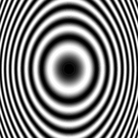
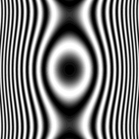
11 What is Astigmatism
12 Astigmatism
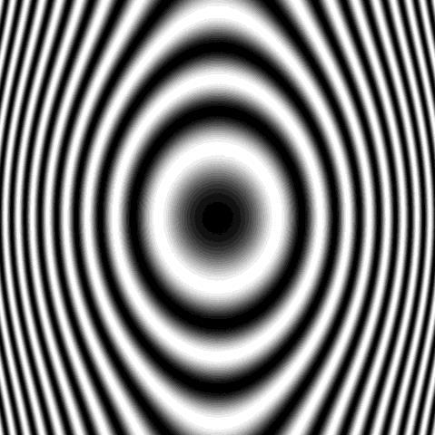
13 Astigmatism
14 Astigmatism
15 Rotation center
16 Rotation center
17 Rotation center
18 Rotation center
19 Rotation center
20 Rotation center
21 Coma free
22 Coma free
23 Coma free
24 Coma free
25 Coma free
26 Coma free
27 Coma free
28 Coma free
29 Coma free
30 Coma free; Illumination passes through a symmetric path through the lens
31 Lenses: Chromatic Aberration Blurring due to energy spread in electron beam and lens current fluctuations Specimen thickness (mean-free-path) Plane of least confusion P a D E 2 D I d = C a c c + E I 31
32 What did we learn? How to optimize the microscope for; Astigmatism» Stigmator for objective lens Rotation center» Direct alignments Coma» Direct alignments» or script to tilt beam and observe FFT» AutoCTF Chromatic aberration» do not use areas where ice is too thick
33 What and how? Cs Corrector


34 History of the Transmission Electron Microscope 1931, Knoll and Ruska Electrostatic lenses, 1933 magnetic lenses BIMR Workshop 2007 Limited by lens defects: aberrations d=0.66c s 1/4 l 3/4 resolution =1-2 Å From H. Rose
35

36

37 Correcting C s The idea of correcting for C s : To create a field which has an opposite character; i.e. the strength (or refraction) of this field should decrease with increasing distance to the optical axis which means negative C s. Why not a concave electron lens? There are no concave electron lenses. Scherzer theorem: C s and C c are always positive for: round lenses no charge on the axis systems where the field do not vary with the time Therefore: C s can only be corrected if the rotational symmetry is given up! 37
38 Spherical Aberration (Cs) Correction Cs corrector Hexa- or dodeca-pole lenses
39 Hexapole Probe C S Corrector Obj Obj Obj Obj Cs-corrector 39
40 The Purpose of a C S Corrector A C S corrector corrects for coherent aberrations, in particular C S. Incoherent aberrations (vibrations, instabilities) or C c are not improved by a C S corrector! BUT, once C S is corrected, other aberrations become important/dominant. Therefore, a corrector not only corrects for C S but for a whole series of coherent aberrations; like astigmatism and coma and aberrations produced by the corrector itself (S3, D4). What s not the purpose of a corrector: A C S corrector does not compensate for a misaligned column! Having a corrector, the optical axis of the microscope is given the column has to be aligned such that it meets this axis, NOT vice versa! 40
 Sample I(x, y)")


 χ odd q = 0")
41 Contrast transfer (Correction) Sample I(x, y) Lens Ab.func. χ Back focal plane F I e iχ Camera F 1 F I sin ( χ even e iχ odd] Optical axis Show result (e.g. as Thon ring positions overlay) u Example Input image f Power spectrum χ even q = 2π λ (1 2 λ2 q 2 Δf+ 1 4 C sq 4 ) χ odd q = 0 Fitted Thon rings defocus + astigmatism value 9/8/
42

43 Spherical Aberration (Cs) Correction Cs corrector Hexa- or dodeca-pole lenses Defocus Twofold astigmatism Axial coma Threefold astigmatism Spherical aberration Star aberration Fourfold astigmatism C1 A1 B2 A2 C3 S3 A3
44 44

45 The phase plate image 17mrad = 1.3 Å Confidence limit of detail represented with smaller than 45 phase change. A2: Threefold astigmatism Next parameter suggested to focus on with optimization mrad = 2.1 Å 6.7 mrad = 3.4 Å 1.3Å Calculated from determined parameters.
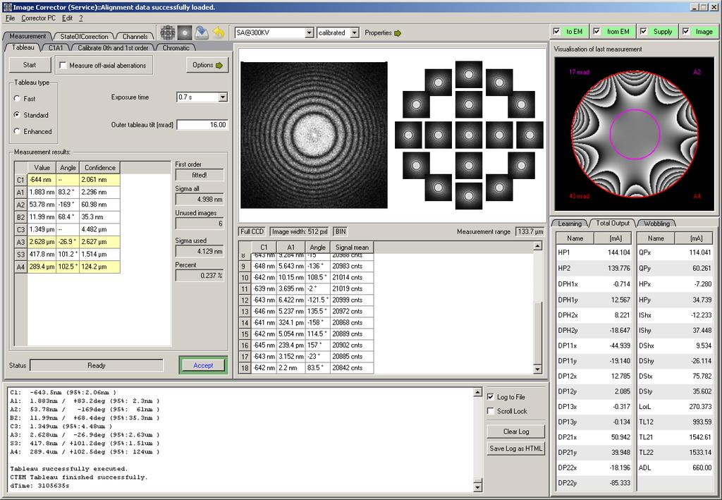
46 What else do you get? Sall: 3.216nm Sused: 3.216nm (1.669%) C1: nm (95%: 4.31nm) A1: 5.626nm / deg (95%: 4.78nm) A2: 109.4nm / deg (95%: 49.4nm) B2: 58.97nm / deg (95%: 41.8nm) C3: 805.3nm (95%: 2.63um) A3: 2.746um / +13.7deg (95%: 508nm) S3: 1.578um / deg (95%: 231nm) A4: 48.34um / deg (95%: 13.1um) D4: 30.57um / +51.5deg (95%: 10.3um) B4: 60.34um / deg (95%: 17.8um) C5: 11.06mm (95%: 1.98mm) A5: 1.918mm / +86.4deg (95%: 377um) Fast tableau (15 mrad) Standard (18-20 mrad) Enhanced (30-35 mrad) Error bar Adjustable Factory adjustable or fixed Azimuth angle Measured value 46


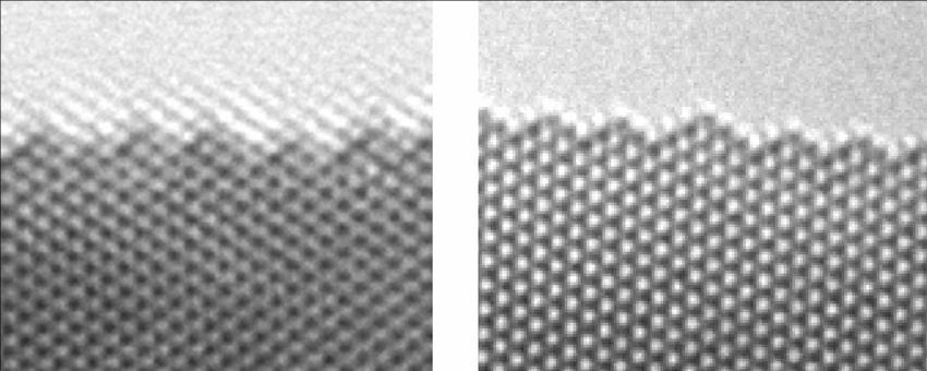
47 Cs Corrector at work Cs = 1.2 mm Cs = mm 2 nm Atomically sharp gold specimen edge OFF ON


48 HR-TEM on Nb 7 W 10 O 47.5 TITAN image Cs-corrector vs. non-cs corrected 300kV 2 nm 2 nm Image : B.Freitag Cs-corrected HR-TEM Non Cs corrected HR-TEM Clear interpretation of atomic structure (Every atomic distance is transferred with the same contrast,[ see CTF])
49
50
51
52
Transmission Electron Microscopy 9. The Instrument. Outline
 Transmission Electron Microscopy 9. The Instrument EMA 6518 Spring 2009 02/25/09 Outline The Illumination System The Objective Lens and Stage Forming Diffraction Patterns and Images Alignment and Stigmation
Introduction to Electron Microscopy
 Introduction to Electron Microscopy Prof. David Muller, dm24@cornell.edu Rm 274 Clark Hall, 255-4065 Ernst Ruska and Max Knoll built the first electron microscope in 1931 (Nobel Prize to Ruska in 1986)
2.Components of an electron microscope. a) vacuum systems, b) electron guns, c) electron optics, d) detectors. Marco Cantoni 021/
 vacuum systems, b) electron guns, c) electron optics, d) detectors. Marco Cantoni 021/") 2.Components of an electron microscope a) vacuum systems, b) electron guns, c) electron optics, d) detectors, 021/693.48.16 Centre Interdisciplinaire de Microscopie Electronique CIME Summary Electron propagation
2.Components of an electron microscope a) vacuum systems, b) electron guns, c) electron optics, d) detectors, 021/693.48.16 Centre Interdisciplinaire de Microscopie Electronique CIME Summary Electron propagation
Chapter 1. Basic Electron Optics (Lecture 2)
") Chapter 1. Basic Electron Optics (Lecture 2) Basic concepts of microscope (Cont ) Fundamental properties of electrons Electron Scattering Instrumentation Basic conceptions of microscope (Cont ) Ray diagram
Chapter 1. Basic Electron Optics (Lecture 2) Basic concepts of microscope (Cont ) Fundamental properties of electrons Electron Scattering Instrumentation Basic conceptions of microscope (Cont ) Ray diagram
Phase plates for cryo-em
 Max Planck Institute of Biochemistry Martinsried, Germany MAX PLANCK SOCIETY Phase plates for cryo-em Rado Danev Max Planck Institute of Biochemistry, Martinsried, Germany. EMBO course 2017, London, UK
2.Components of an electron microscope. a) vacuum systems, b) electron guns, c) electron optics, d) detectors. Marco Cantoni, 021/
 vacuum systems, b) electron guns, c) electron optics, d) detectors. Marco Cantoni, 021/") 2.Components of an electron microscope a) vacuum systems, b) electron guns, c) electron optics, d) detectors Marco Cantoni, 021/693.48.16 Centre Interdisciplinaire de Microscopie Electronique CIME MSE-603
2.Components of an electron microscope a) vacuum systems, b) electron guns, c) electron optics, d) detectors Marco Cantoni, 021/693.48.16 Centre Interdisciplinaire de Microscopie Electronique CIME MSE-603
TEM theory Basic optics, image formation and key elements
 Workshop series of Chinese 3DEM community Get acquainted with Cryo-Electron Microscopy: First Chinese Workshop for Structural Biologists TEM theory Basic optics, image formation and key elements Jianlin
CS-TEM vs CS-STEM. FEI Titan CIME EPFL. Duncan Alexander EPFL-CIME
 CS-TEM vs CS-STEM Duncan Alexander EPFL-CIME 1 FEI Titan Themis @ CIME EPFL 60 300 kv Monochromator High brightness X-FEG Probe Cs-corrected: 0.7 Å @ 300 kv Image Cs-corrected: 0.7 Å @ 300 kv Super-X EDX
WIEN Software for Design of Columns Containing Wien Filters and Multipole Lenses
 WIEN Software for Design of Columns Containing Wien Filters and Multipole Lenses An integrated workplace for analysing and optimising the column optics Base Package (WIEN) Handles round lenses, quadrupoles,
Software for Electron and Ion Beam Column Design. An integrated workplace for simulating and optimizing electron and ion beam columns
 OPTICS Software for Electron and Ion Beam Column Design An integrated workplace for simulating and optimizing electron and ion beam columns Base Package (OPTICS) Field computation Imaging and paraxial
Waves & Oscillations
 Physics 42200 Waves & Oscillations Lecture 33 Geometric Optics Spring 2013 Semester Matthew Jones Aberrations We have continued to make approximations: Paraxial rays Spherical lenses Index of refraction
Diffractogram tableaux by mouse click
 Ultramicroscopy 93 (2002) 77 82 Diffractogram tableaux by mouse click Johannes Zemlin a, Friedrich Zemlin b, * a Lichter felder Ring 123, D-12209 Berlin, Germany b Fritz-Haber-Institut der MPG, Abteilung
Aberration corrected tilt series restoration
 Journal of Physics: Conference Series Aberration corrected tilt series restoration To cite this article: S Haigh et al 2008 J. Phys.: Conf. Ser. 126 012042 Recent citations - Artefacts in geometric phase
High-resolution imaging on C s -corrected Titan
 High-resolution imaging on C s -corrected Titan 80-300 A new era for new results In NanoResearch a detailed knowledge of the structure of the material down to the atomic level is crucial for understanding
Supplementary Figure 1. 2-Fold astigmatism. (a-f) Multi-slice image simulations of graphene structure with variation of the level of 2-fold
 Multi-slice image simulations of graphene structure with variation of the level of 2-fold") Supplementary Figure 1. 2-Fold astigmatism. (a-f) Multi-slice image simulations of graphene structure with variation of the level of 2-fold astigmatism increasing from 0 to 1.0 nm with an interval of 0.2nm.
Supplementary Figure 1. 2-Fold astigmatism. (a-f) Multi-slice image simulations of graphene structure with variation of the level of 2-fold astigmatism increasing from 0 to 1.0 nm with an interval of 0.2nm.
s 2 stigmator: a closed-form solution for single-pass correction of TEM lens astigmatism
 s 2 stigmator: a closed-form solution for single-pass correction of TEM lens astigmatism Rui Yan, Kunpeng Li, Wen Jiang http://cryoem.bio.purdue.edu http://jiang.bio.purdue.edu Purdue Cryo-EM Facility
Contrast transfer. Contrast transfer and CTF correction. Lecture 6 H Saibil
 Lecture 6 H Saibil Contrast transfer Contrast transfer and CTF correction The weak phase approximation Contrast transfer function Determining defocus CTF correction methods Image processing for cryo microscopy
Chapter 2 Instrumentation for Analytical Electron Microscopy Lecture 7. Chapter 2 CHEM Fall L. Ma
 Chapter 2 Instrumentation for Analytical Electron Microscopy Lecture 7 Outline Electron Sources (Electron Guns) Thermionic: LaB 6 or W Field emission gun: cold or Schottky Lenses Focusing Aberration Probe
Electron Sources, Optics and Detectors
 Thomas LaGrange, Ph.D. Faculty Lecturer and Senior Staff Scientist Electron Sources, Optics and Detectors TEM Doctoral Course MS-637 April 16 th -18 th, 2018 Summary Electron propagation is only possible
INTRODUCTION TO ABERRATIONS IN OPTICAL IMAGING SYSTEMS
 INTRODUCTION TO ABERRATIONS IN OPTICAL IMAGING SYSTEMS JOSE SASIÄN University of Arizona ШШ CAMBRIDGE Щ0 UNIVERSITY PRESS Contents Preface Acknowledgements Harold H. Hopkins Roland V. Shack Symbols 1 Introduction
CS-TEM vs CS-STEM. FEI Titan CIME EPFL. Duncan Alexander EPFL-CIME
 CS-TEM vs CS-STEM Duncan Alexander EPFL-CIME 1 FEI Titan Themis @ CIME EPFL 60 300 kv Monochromator High brightness X-FEG Probe Cs-corrected: 0.7 Å @ 300 kv Image Cs-corrected: 0.7 Å @ 300 kv Super-X EDX
High Resolution Transmission Electron Microscopy (HRTEM) Summary 4/11/2018. Thomas LaGrange Faculty Lecturer and Senior Staff Scientist
 Summary 4/11/2018. Thomas LaGrange Faculty Lecturer and Senior Staff Scientist") Thomas LaGrange Faculty Lecturer and Senior Staff Scientist High Resolution Transmission Electron Microscopy (HRTEM) Doctoral Course MS-637 April 16-18th, 2018 Summary Contrast in TEM images results from
Thomas LaGrange Faculty Lecturer and Senior Staff Scientist High Resolution Transmission Electron Microscopy (HRTEM) Doctoral Course MS-637 April 16-18th, 2018 Summary Contrast in TEM images results from
Recent results from the JEOL JEM-3000F FEGTEM in Oxford
 Recent results from the JEOL JEM-3000F FEGTEM in Oxford R.E. Dunin-Borkowski a, J. Sloan b, R.R. Meyer c, A.I. Kirkland c,d and J. L. Hutchison a a b c d Department of Materials, Parks Road, Oxford OX1
Atomic Resolution Imaging with a sub-50 pm Electron Probe
 Atomic Resolution Imaging with a sub-50 pm Electron Probe Rolf Erni, Marta D. Rossell, Christian Kisielowski, Ulrich Dahmen National Center for Electron Microscopy, Lawrence Berkeley National Laboratory
Introduction to Transmission Electron Microscopy (Physical Sciences)
") Introduction to Transmission Electron Microscopy (Physical Sciences) Centre for Advanced Microscopy Program 9:30 10:45 Lecture 1 Basics of TEM 10:45 11:00 Morning tea 11:00 12:15 Lecture 2 Diffraction
Introduction to Transmission Electron Microscopy (Physical Sciences) Centre for Advanced Microscopy Program 9:30 10:45 Lecture 1 Basics of TEM 10:45 11:00 Morning tea 11:00 12:15 Lecture 2 Diffraction
COURSE NAME: PHOTOGRAPHY AND AUDIO VISUAL PRODUCTION (VOCATIONAL) FOR UNDER GRADUATE (FIRST YEAR)
 FOR UNDER GRADUATE (FIRST YEAR)") COURSE NAME: PHOTOGRAPHY AND AUDIO VISUAL PRODUCTION (VOCATIONAL) FOR UNDER GRADUATE (FIRST YEAR) PAPER TITLE: BASIC PHOTOGRAPHIC UNIT - 3 : SIMPLE LENS TOPIC: LENS PROPERTIES AND DEFECTS OBJECTIVES By
COURSE NAME: PHOTOGRAPHY AND AUDIO VISUAL PRODUCTION (VOCATIONAL) FOR UNDER GRADUATE (FIRST YEAR) PAPER TITLE: BASIC PHOTOGRAPHIC UNIT - 3 : SIMPLE LENS TOPIC: LENS PROPERTIES AND DEFECTS OBJECTIVES By
Full-screen mode Popup controls. Overview of the microscope user interface, TEM User Interface and TIA on the left and EDS on the right
 Quick Guide to Operating FEI Titan Themis G2 200 (S)TEM: TEM mode Susheng Tan Nanoscale Fabrication and Characterization Facility, University of Pittsburgh Office: M104/B01 Benedum Hall, 412-383-5978,
GBS765 Hybrid methods
 GBS765 Hybrid methods Lecture 3 Contrast and image formation 10/20/14 4:37 PM The lens ray diagram Magnification M = A/a = v/u and 1/u + 1/v = 1/f where f is the focal length The lens ray diagram So we
Electron
 Electron 1897: Sir Joseph John Thomson (1856-1940) discovered corpuscles small particles with a charge-to-mass ratio over 1000 times greater than that of protons. Plum pudding model : electrons in a sea
Converging and Diverging Surfaces. Lenses. Converging Surface
 Lenses Sandy Skoglund 2 Converging and Diverging s AIR Converging If the surface is convex, it is a converging surface in the sense that the parallel rays bend toward each other after passing through the
 Telecentric Imaging Object space telecentricity stop source: edmund optics The 5 classical Seidel Aberrations First order aberrations Spherical Aberration (~r 4 ) Origin: different focal lengths for different
A few concepts in TEM and STEM explained
 A few concepts in TEM and STEM explained Martin Ek November 23, 2011 1 Introduction This is a collection of short, qualitative explanations of key concepts in TEM and STEM. Most of them are beyond what
The application of spherical aberration correction and focal series restoration to high-resolution images of platinum nanocatalyst particles
 Journal of Physics: Conference Series The application of spherical aberration correction and focal series restoration to high-resolution images of platinum nanocatalyst particles Recent citations - Miguel
OPTICAL IMAGING AND ABERRATIONS
 OPTICAL IMAGING AND ABERRATIONS PARTI RAY GEOMETRICAL OPTICS VIRENDRA N. MAHAJAN THE AEROSPACE CORPORATION AND THE UNIVERSITY OF SOUTHERN CALIFORNIA SPIE O P T I C A L E N G I N E E R I N G P R E S S A
Lecture 2: Geometrical Optics. Geometrical Approximation. Lenses. Mirrors. Optical Systems. Images and Pupils. Aberrations.
 Lecture 2: Geometrical Optics Outline 1 Geometrical Approximation 2 Lenses 3 Mirrors 4 Optical Systems 5 Images and Pupils 6 Aberrations Christoph U. Keller, Leiden Observatory, keller@strw.leidenuniv.nl
Lenses. A transparent object used to change the path of light Examples: Human eye Eye glasses Camera Microscope Telescope
 SNC2D Lenses A transparent object used to change the path of light Examples: Human eye Eye glasses Camera Microscope Telescope Reading stones used by monks, nuns, and scholars ~1000 C.E. Lenses THERE ARE
Cardinal Points of an Optical System--and Other Basic Facts
 Cardinal Points of an Optical System--and Other Basic Facts The fundamental feature of any optical system is the aperture stop. Thus, the most fundamental optical system is the pinhole camera. The image
Introduction to Electron Microscopy-II
 Introduction to Electron Microscopy-II Prof. David Muller, dm24@cornell.edu Rm 274 Clark Hall, 255-4065 Ernst Ruska and Max Knoll built the first electron microscope in 1931 (Nobel Prize to Ruska in 1986)
Geometric optics & aberrations
 Geometric optics & aberrations Department of Astrophysical Sciences University AST 542 http://www.northerneye.co.uk/ Outline Introduction: Optics in astronomy Basics of geometric optics Paraxial approximation
Image Contrast Theory
 Image Contrast Theory Wah Chiu wah@bcm.tmc.edu National Center for Macromolecular Imaging References Jiang, W. & Chiu, W. Web-based simulation for contrast transfer function and envelope functions. Microsc
Optical Engineering 421/521 Sample Questions for Midterm 1
 Optical Engineering 421/521 Sample Questions for Midterm 1 Short answer 1.) Sketch a pechan prism. Name a possible application of this prism., write the mirror matrix for this prism (or any other common
Lecture 2: Geometrical Optics. Geometrical Approximation. Lenses. Mirrors. Optical Systems. Images and Pupils. Aberrations.
 Lecture 2: Geometrical Optics Outline 1 Geometrical Approximation 2 Lenses 3 Mirrors 4 Optical Systems 5 Images and Pupils 6 Aberrations Christoph U. Keller, Leiden Observatory, keller@strw.leidenuniv.nl
No part of this material may be reproduced without explicit written permission.
 This material is provided for educational use only. The information in these slides including all data, images and related materials are the property of : Robert M. Glaeser Department of Molecular & Cell
Chapter 1. Introduction
 Chapter 1 Introduction 1.1 Where are the Atoms? Uncovering objects that are too small to be seen by eye: this is the primary purpose of microscopy. The human eye enables us to resolve objects that are
How to choose the optimal microscope/camera combinations
 How to choose the optimal microscope/camera combinations The Practical Matters Anchi Cheng National Resource for Automated Common Mistakes I have money; I will get everything, regardless. I don t have
ECEN 4606, UNDERGRADUATE OPTICS LAB
 ECEN 4606, UNDERGRADUATE OPTICS LAB Lab 2: Imaging 1 the Telescope Original Version: Prof. McLeod SUMMARY: In this lab you will become familiar with the use of one or more lenses to create images of distant
Tecnai on-line help manual --
 Tecnai on-line help Alignments 1 Tecnai on-line help manual -- Alignments Table of Contents 1 Alignments in the Tecnai microscope...5 2 Alignment procedures...6 3 Introduction to electron optics...11 3.1
AST Lab exercise: aberrations
 AST2210 - Lab exercise: aberrations 1 Introduction This lab exercise will take you through the most common types of aberrations. 2 Chromatic aberration Chromatic aberration causes lens to have dierent
Tutorial on Linear Image Simulations of Phase-Contrast and Incoherent Imaging by convolutions
 Tutorial on Linear Image Simulations of Phase-Contrast and Incoherent Imaging by convolutions Huolin Xin, David Muller, based on Appendix A of Kirkland s book This tutorial covers the use of temcon and
Transmission electron Microscopy
 Transmission electron Microscopy Image formation of a concave lens in geometrical optics Some basic features of the transmission electron microscope (TEM) can be understood from by analogy with the operation
The optical analysis of the proposed Schmidt camera design.
 The optical analysis of the proposed Schmidt camera design. M. Hrabovsky, M. Palatka, P. Schovanek Joint Laboratory of Optics of Palacky University and Institute of Physics of the Academy of Sciences of
J. C. Wyant Fall, 2012 Optics Optical Testing and Testing Instrumentation
 J. C. Wyant Fall, 2012 Optics 513 - Optical Testing and Testing Instrumentation Introduction 1. Measurement of Paraxial Properties of Optical Systems 1.1 Thin Lenses 1.1.1 Measurements Based on Image Equation
Diffractive Axicon application note
 Diffractive Axicon application note. Introduction 2. General definition 3. General specifications of Diffractive Axicons 4. Typical applications 5. Advantages of the Diffractive Axicon 6. Principle of
Chapter Ray and Wave Optics
 109 Chapter Ray and Wave Optics 1. An astronomical telescope has a large aperture to [2002] reduce spherical aberration have high resolution increase span of observation have low dispersion. 2. If two
Quantitative HRTEM investigation of an obtuse angle dislocation reaction in gold with a C S corrected field emission microscope
 Quantitative HRTEM investigation of an obtuse angle dislocation reaction in gold with a C S corrected field emission microscope Joerg R. Jinschek 1, Ch. Kisielowski 1,2, T. Radetic 1, U. Dahmen 1, M. Lentzen
OPAL. SpotOptics. AUTOMATED WAVEFRONT SENSOR Single and double pass O P A L
 Spotptics The software people for optics UTMTED WVEFRNT SENSR Single and double pass ccurate metrology of standard and aspherical lenses ccurate metrology of spherical and flat mirrors =0.3 to =60 mm F/1
MSE 460 TEM Lab 2: Basic Alignment and Operation of Microscope
 MSE 460 TEM Lab 2: Basic Alignment and Operation of Microscope Last updated on 1/8/2018 Jinsong Wu, jinsong-wu@northwestern.edu Aims: The aim of this lab is to familiarize you with basic TEM alignment
BMB/Bi/Ch 173 Winter 2018
 BMB/Bi/Ch 73 Winter 208 Homework Set 2 (200 Points) Assigned -7-8, due -23-8 by 0:30 a.m. TA: Rachael Kuintzle. Office hours: SFL 229, Friday /9 4:00-5:00pm and SFL 220, Monday /22 4:00-5:30pm. For the
ELECTRON MICROSCOPY. 13:10 16:00, Oct. 6, 2008 Institute of Physics, Academia Sinica. Tung Hsu
 ELECTRON MICROSCOPY 13:10 16:00, Oct. 6, 2008 Institute of Physics, Academia Sinica Tung Hsu Department of Materials Science and Engineering National Tsing Hua University Hsinchu 300, TAIWAN Tel. 03-5742564
3.0 Alignment Equipment and Diagnostic Tools:
 3.0 Alignment Equipment and Diagnostic Tools: Alignment equipment The alignment telescope and its use The laser autostigmatic cube (LACI) interferometer A pin -- and how to find the center of curvature
ELECTRON OPTICS. Prof. John G. King Dr. John W. Coleman Dr. Edward H. Jacobsen. Graduate Students. Steven R. Jost Norman D. Punsky
 II. ELECTRON OPTICS Academic and Research Staff Prof. John G. King Dr. John W. Coleman Dr. Edward H. Jacobsen Graduate Students Steven R. Jost Norman D. Punsky A. HIGH-RESOLUTION HIGH-CONTRAST ELECTRON
Nanotechnology in Consumer Products
 Nanotechnology in Consumer Products Advances in Transmission Electron Microscopy Friday, April 21, 2017 October 31, 2014 The webinar will begin at 1pm Eastern Time Click here to watch the webinar recording
CTF Correction with IMOD
 CTF Correction with IMOD CTF Correction When microscope is operated in underfocus to produce phase contrast, the contrast is inverted in some spatial frequency ranges 1 We See Only Amplitudes, Not Phases,
BEAM HALO OBSERVATION BY CORONAGRAPH
 BEAM HALO OBSERVATION BY CORONAGRAPH T. Mitsuhashi, KEK, TSUKUBA, Japan Abstract We have developed a coronagraph for the observation of the beam halo surrounding a beam. An opaque disk is set in the beam
Converging Lenses. Parallel rays are brought to a focus by a converging lens (one that is thicker in the center than it is at the edge).
.") Chapter 30: Lenses Types of Lenses Piece of glass or transparent material that bends parallel rays of light so they cross and form an image Two types: Converging Diverging Converging Lenses Parallel rays
Chapter 30: Lenses Types of Lenses Piece of glass or transparent material that bends parallel rays of light so they cross and form an image Two types: Converging Diverging Converging Lenses Parallel rays
Aberrations and adaptive optics for biomedical microscopes
 Aberrations and adaptive optics for biomedical microscopes Martin Booth Department of Engineering Science And Centre for Neural Circuits and Behaviour University of Oxford Outline Rays, wave fronts and
NANO 703-Notes. Chapter 9-The Instrument
 1 Chapter 9-The Instrument Illumination (condenser) system Before (above) the sample, the purpose of electron lenses is to form the beam/probe that will illuminate the sample. Our electron source is macroscopic
Optical design of a high resolution vision lens
 Optical design of a high resolution vision lens Paul Claassen, optical designer, paul.claassen@sioux.eu Marnix Tas, optical specialist, marnix.tas@sioux.eu Prof L.Beckmann, l.beckmann@hccnet.nl Summary:
Microscope Imaging. Colin Sheppard Nano- Physics Department Italian Ins:tute of Technology (IIT) Genoa, Italy
 Genoa, Italy") Microscope Imaging Colin Sheppard Nano- Physics Department Italian Ins:tute of Technology (IIT) Genoa, Italy colinjrsheppard@gmail.com Objec:ve lens Op:cal microscope Numerical aperture (n sin α) Air /
Microscope Imaging Colin Sheppard Nano- Physics Department Italian Ins:tute of Technology (IIT) Genoa, Italy colinjrsheppard@gmail.com Objec:ve lens Op:cal microscope Numerical aperture (n sin α) Air /
Cover Page. The handle holds various files of this Leiden University dissertation.
 Cover Page The handle http://hdl.handle.net/1887/2083 holds various files of this Leiden University dissertation. Author: Schramm, Sebastian Markus Title: Imaging with aberration-corrected low energy electron
Oct. 30th- Nov. 1st, 2017
 Thomas LaGrange, Ph.D. Faculty Lecturer and Senior Staff Scientist Electron Sources, Optics and Detectors SEM Doctoral Course MS-636 Oct. 30th- Nov. 1st, 2017 Summary Electron propagation is only possible
Lecture 4: Geometrical Optics 2. Optical Systems. Images and Pupils. Rays. Wavefronts. Aberrations. Outline
 Lecture 4: Geometrical Optics 2 Outline 1 Optical Systems 2 Images and Pupils 3 Rays 4 Wavefronts 5 Aberrations Christoph U. Keller, Leiden University, keller@strw.leidenuniv.nl Lecture 4: Geometrical
Lecture 3: Geometrical Optics 1. Spherical Waves. From Waves to Rays. Lenses. Chromatic Aberrations. Mirrors. Outline
 Lecture 3: Geometrical Optics 1 Outline 1 Spherical Waves 2 From Waves to Rays 3 Lenses 4 Chromatic Aberrations 5 Mirrors Christoph U. Keller, Leiden Observatory, keller@strw.leidenuniv.nl Lecture 3: Geometrical
SNC2D PHYSICS 5/25/2013. LIGHT & GEOMETRIC OPTICS L Converging & Diverging Lenses (P ) Curved Lenses. Curved Lenses
 Curved Lenses. Curved Lenses") SNC2D PHYSICS LIGHT & GEOMETRIC OPTICS L Converging & Diverging Lenses (P.448-450) Curved Lenses We see the world through lenses even if we do not wear glasses or contacts. We all have natural lenses in
SNC2D PHYSICS LIGHT & GEOMETRIC OPTICS L Converging & Diverging Lenses (P.448-450) Curved Lenses We see the world through lenses even if we do not wear glasses or contacts. We all have natural lenses in
Reflectors vs. Refractors
 1 Telescope Types - Telescopes collect and concentrate light (which can then be magnified, dispersed as a spectrum, etc). - In the end it is the collecting area that counts. - There are two primary telescope
ELECTRON MICROSCOPY. 14:10 17:00, Apr. 3, 2007 Department of Physics, National Taiwan University. Tung Hsu
 ELECTRON MICROSCOPY 14:10 17:00, Apr. 3, 2007 Department of Physics, National Taiwan University Tung Hsu Department of Materials Science and Engineering National Tsinghua University Hsinchu 300, TAIWAN
Numerical analysis to verifying the performance of condenser magnetic lens in the scanning electron microscope.
 Numerical analysis to verifying the performance of condenser magnetic lens in the scanning electron microscope. Mohammed Abdullah Hussein Dept. of mechanization and agricultural equipment, College of agriculture
S200 Course LECTURE 1 TEM
 S200 Course LECTURE 1 TEM Development of Electron Microscopy 1897 Discovery of the electron (J.J. Thompson) 1924 Particle and wave theory (L. de Broglie) 1926 Electromagnetic Lens (H. Busch) 1932 Construction
Tutorial Zemax Introduction 1
 Tutorial Zemax Introduction 1 2012-07-17 1 Introduction 1 1.1 Exercise 1-1: Stair-mirror-setup... 1 1.2 Exercise 1-2: Symmetrical 4f-system... 5 1 Introduction 1.1 Exercise 1-1: Stair-mirror-setup Setup
VISUAL PHYSICS ONLINE DEPTH STUDY: ELECTRON MICROSCOPES
 VISUAL PHYSICS ONLINE DEPTH STUDY: ELECTRON MICROSCOPES Shortly after the experimental confirmation of the wave properties of the electron, it was suggested that the electron could be used to examine objects
Image Formation. Light from distant things. Geometrical optics. Pinhole camera. Chapter 36
 Light from distant things Chapter 36 We learn about a distant thing from the light it generates or redirects. The lenses in our eyes create images of objects our brains can process. This chapter concerns
PHYSICS OPTICS. Mr Rishi Gopie
 OPTICS Mr Rishi Gopie Ray Optics II Images formed by lens maybe real or virtual and may have different characteristics and locations that depend on: i) The type of lens involved, whether converging or
Opti 415/515. Introduction to Optical Systems. Copyright 2009, William P. Kuhn
 Opti 415/515 Introduction to Optical Systems 1 Optical Systems Manipulate light to form an image on a detector. Point source microscope Hubble telescope (NASA) 2 Fundamental System Requirements Application
CHAPTER TWO METALLOGRAPHY & MICROSCOPY
 CHAPTER TWO METALLOGRAPHY & MICROSCOPY 1. INTRODUCTION: Materials characterisation has two main aspects: Accurately measuring the physical, mechanical and chemical properties of materials Accurately measuring
25 cm. 60 cm. 50 cm. 40 cm.
 Geometrical Optics 7. The image formed by a plane mirror is: (a) Real. (b) Virtual. (c) Erect and of equal size. (d) Laterally inverted. (e) B, c, and d. (f) A, b and c. 8. A real image is that: (a) Which
Design of a high brightness multi-electron-beam source
 vailable online at www.sciencedirect.com Physics Procedia00 1 (2008) 000 000 553 563 www.elsevier.com/locate/procedia www.elsevier.com/locate/xxx Proceedings of the Seventh International Conference on
Explanation of Aberration and Wavefront
 Explanation of Aberration and Wavefront 1. What Causes Blur? 2. What is? 4. What is wavefront? 5. Hartmann-Shack Aberrometer 6. Adoption of wavefront technology David Oh 1. What Causes Blur? 2. What is?
ECEG105/ECEU646 Optics for Engineers Course Notes Part 4: Apertures, Aberrations Prof. Charles A. DiMarzio Northeastern University Fall 2008
 ECEG105/ECEU646 Optics for Engineers Course Notes Part 4: Apertures, Aberrations Prof. Charles A. DiMarzio Northeastern University Fall 2008 July 2003+ Chuck DiMarzio, Northeastern University 11270-04-1
Optical Design with Zemax
 Optical Design with Zemax Lecture : Correction II 3--9 Herbert Gross Summer term www.iap.uni-jena.de Correction II Preliminary time schedule 6.. Introduction Introduction, Zemax interface, menues, file
Laboratory experiment aberrations
 Laboratory experiment aberrations Obligatory laboratory experiment on course in Optical design, SK2330/SK3330, KTH. Date Name Pass Objective This laboratory experiment is intended to demonstrate the most
Astronomical Observing Techniques Lecture 6: Op:cs
 Astronomical Observing Techniques Lecture 6: Op:cs Christoph U. Keller keller@strw.leidenuniv.nl Outline 1. Geometrical Op
Point Spread Function. Confocal Laser Scanning Microscopy. Confocal Aperture. Optical aberrations. Alternative Scanning Microscopy
 Bi177 Lecture 5 Adding the Third Dimension Wide-field Imaging Point Spread Function Deconvolution Confocal Laser Scanning Microscopy Confocal Aperture Optical aberrations Alternative Scanning Microscopy
Titan on-line help manual -- Working with a FEG
 1 manual -- Working with a FEG Table of Contents 1 FEG Safety... 2 1.1 The column valves... 2 2 FEG States... 2 3 Starting the FEG... 4 4 Shutting the FEG down... 6 5 FEG Design... 6 5.1 Electron source...
MSE 460 TEM Lab 4: Bright/Dark Field Imaging Operation
 MSE 460 TEM Lab 4: Bright/Dark Field Imaging Operation Last updated on 1/8/2018 Jinsong Wu, jinsong-wu@northwestern.edu Aims: The aim of this lab is to familiarize you with bright/dark field imaging operation.
Why is There a Black Dot when Defocus = 1λ?
 Why is There a Black Dot when Defocus = 1λ? W = W 020 = a 020 ρ 2 When a 020 = 1λ Sag of the wavefront at full aperture (ρ = 1) = 1λ Sag of the wavefront at ρ = 0.707 = 0.5λ Area of the pupil from ρ =
NanoSpective, Inc Progress Drive Suite 137 Orlando, Florida
 TEM Techniques Summary The TEM is an analytical instrument in which a thin membrane (typically < 100nm) is placed in the path of an energetic and highly coherent beam of electrons. Typical operating voltages
Mirrors and Lenses. Images can be formed by reflection from mirrors. Images can be formed by refraction through lenses.
 Mirrors and Lenses Images can be formed by reflection from mirrors. Images can be formed by refraction through lenses. Notation for Mirrors and Lenses The object distance is the distance from the object
Exercises Advanced Optical Design Part 5 Solutions
 2014-12-09 Manuel Tessmer M.Tessmer@uni-jena.dee Minyi Zhong minyi.zhong@uni-jena.de Herbert Gross herbert.gross@uni-jena.de Friedrich Schiller University Jena Institute of Applied Physics Albert-Einstein-Str.
LENSES. a. To study the nature of image formed by spherical lenses. b. To study the defects of spherical lenses.
 Purpose Theory LENSES a. To study the nature of image formed by spherical lenses. b. To study the defects of spherical lenses. formation by thin spherical lenses s are formed by lenses because of the refraction
A Tutorial on Electron Microscopy
 A Tutorial on Electron Microscopy Jian-Min (Jim) Zuo Mat. Sci. Eng. and Seitz-Materials Research Lab., UIUC Outline of This Tutorial I. Science and opportunities of electron microscopy II. The basic TEM,