Chapter 2 Instrumentation for Analytical Electron Microscopy Lecture 7. Chapter 2 CHEM Fall L. Ma
|
|
|
- Stuart Sutton
- 6 years ago
- Views:
Transcription

1 Chapter 2 Instrumentation for Analytical Electron Microscopy Lecture 7
2 Outline Electron Sources (Electron Guns) Thermionic: LaB 6 or W Field emission gun: cold or Schottky Lenses Focusing Aberration Probe size Detectors electron detectors X-ray detectors energy loss spectrometers Imaging Diffraction Bright field imaging (BF) Dark field imaging (DF) Phase contrast imaging (HRTEM) mode Scanning transmission electron microscopy (STEM) mode Holography mode (not covered) etc.

3 Illumination system: SEM and TEM are similar Objective lens and stage Observation /imaging system

4 Lens A lens is an optical component which is used to focus beams of radiation. Lenses for light are usually made of a glassy material, whereas nonuniform electromagnetic fields are used as lens for electrons. Magnetic field, B Current, I, in coil
5 Magnetic Lenses Electron ray paths A magnetic lens consists of a wire winding around a soft iron core The magnetic field in the lens deflects the electron path, resulting in a focusing of the beam Right hand rule of vector product to determine the force on the electron r F r d 2 r = m dt 2 = r r ( r ) ( r ) q E + v B = e v B r
6 B Paraxial trajectory governing equation Φ: potential Z r ө m e B dz d r B dz r d = Φ = = Φ + η η θ η B ev dt r d m r r r = 2 2 P.W. Hawkes, Electron optics and electron microscopy, 1989, Taylor & Francis Ltd., ISBN

7 Vz Br Upper pole-piece B Bz BFP f lower pole-piece Focusing action of magnetic lens Optical Axis

8 Summary: The magnetic lens produces a strong magnetic field B by passing a current through a set of windings (copper coil). In TEM, this field act as a convex lens, bringing off axis rays back to focus. For magnetic lens, the image is rotated to a degree depending on the strength of the lens. Focal length also can be changed by changing the strength of the current, and thereby of B. Convex lens A convex lens (for light) is thicker in the centre than at its periphery. All electromagnetic lenses used in electron microscopy act as if they were convex lenses. Image is rotated Convex lens

9 Summary 2: All electronmagnetic lenses act like thin convex lenses. So their thickness can be ignored. Equations for convex lens are applicable, like lens formula 1/f= 1/v+ 1/u Magnification: M=v/u

10 E-gun Schematic lens configuration of a TEM system

11 In electron microscope, double condenser (C1 and C2) system is used to adjust the illumination condition. The double condenser system or illumination system consists of two or more lenses and an aperture. It is used in both SEM and TEM. Its function is to control spot size (C1) and beam convergence and intensity (C2). Two or more lenses can act together and their ray diagrams can be constructed using the thin lens approximation for each of them. The diagram opposite shows the ray diagram for the double condenser system. The black dots represent the focal point of each lens.

12 First condenser lens C1 the first condenser lens is shown highlighted in the diagram. Its function is to create a demagnified image of the gun crossover, which acts as the object for the illumination system control the minimum spot size obtainable in the rest of the condenser system.

13 Second condenser lens C2 C2 is adjusted the focus to produce an image of gun crossover at the front focal plane of the upper objective polepiece, and then generate a broad parallel beam of electron incident on the specimen. C2 can affects the convergence of the beam at the specimen, and the diameter of the illuminated area of the specimen. Question: Sitting at the microscope you can only see the image of the specimen on the fluorescent screen. How would you know when the condenser lens (C2) is focused on the specimen? If you now go away from this condition how could you tell whether the beam was overfocused or underfocused?"

14 Condenser aperture The condenser aperture controls the fraction of the beam which is allowed to hit the specimen. It therefore helps to control the intensity of illumination, and in the SEM, the depth of field.

15 Parallel beam with large aperture, i.e. large convergence. Parallel beam with small aperture, i.e. small convergence.

16 Objective lens and specimen stage Heart of TEM The objective lens forms an inverted initial image, which is subsequently magnified. In the back focal plane of the objective lens a diffraction pattern is formed. The objective aperture can be inserted here. The effect of inserting the aperture is shown on the next page. The objective lens would not usually provide a magnification of more than 50 and a TEM is routinely used to view regions of the specimen which are only a mm or so across. What does this imply about the diameter of a typical aperture if it were placed at the back focal plane as shown in this diagram? Diffraction (prior knowledge) Diffraction is an interference effect which leads to the scattering of strong beams of radiation in specific directions. Diffraction from crystals is described by the Bragg Law n λ = 2 d sin θ where n is an integer (the order of scattering), λ is the wavelength of the radiation, d is the spacing between the scattering entities (e.g. planes of atoms in the crystal) and θ is the angle of scattering. Electron and X-ray diffraction are both particularly powerful because their wavelengths are smaller than the typical spacings of atoms in crystals and strong, easily measurable, diffraction occurs.

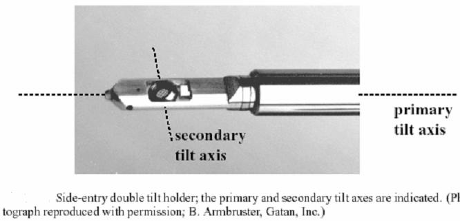
17 Cross-sectional view of the Chapter gonionmeter 2 CHEM area of the Fall JEOL 120 CX microscope
18
19

 In microscopy, contrast is the difference in intensity between a feature of interest (Is) and its background (I0).")
20 Objective aperture The objective aperture is placed in the back focal plane of the image. Its function is to select those electrons which will contribute to the image, and thereby affect the appearance of the image and improve the contrast of the final image. Assist to focus the diffraction image. Aperture removed Diffraction patterns are formed in BFP Contrast (prior knowledge) In microscopy, contrast is the difference in intensity between a feature of interest (Is) and its background (I0). Contrast is usually described as a fraction such as: (Is-I0)/Is. The term has also been extended to mean the physical mechanism by which a feature can be seen on its background (e.g. dislocation contrast in TEM). Aperture inserted In summary, the objective lens is to take electrons emerging from the exit surface of the specimen, disperse them to create a diffraction pattern (DP) in the BFP, and recombine them to form an image in the image plane

21 Objective aperture Change focal strength SAD aperture Intermediate lens The first intermediate lens magnifies the initial image that is formed by the objective lens. The lens can be focused on initial image formed by the objective lens, or Diffraction pattern formed in the back focal plane of the objective lens. This determines whether the viewing screen of Chapter the microscope 2 CHEM shows 793 a diffraction Fall pattern or an image.

 No aperture - the diffraction pattern is centered on the optical axis. (b). Aperture is centered on the optical axis.")
22 TEM operation mode Setting and beam condition TEM operation mode: 1. Parallel beam Bright-field imaging mode Dark-field image mode HRTEM many beam condition SAD mode 2. Convergent beam STEM mode CBED mode 3. Holography mode ( optional) Beam Condition Image mode By inserting the aperture or tilting the beam, different types of images can be formed. The most common conditions are: (a) No aperture - the diffraction pattern is centered on the optical axis. (b). Aperture is centered on the optical axis. (c). Aperture displaced, selecting a diffracted beam. (d) Beam is tilted so that the diffracted beam is on the optical axis.

23 Bright field mode (BF) In the bright field (BF) mode of the TEM, an aperture is placed in the back focal plane (BFP) of the objective lens which allows only the direct beam to pass. In this case, the image results from a weakening of the direct beam by its interaction with the sample. Therefore, mass-thickness and diffraction contrast contribute to image formation: thick areas, areas in which heavy atoms are enriched, and crystalline areas appear with dark contrast. It should be mentioned that the interpretation of images is often impeded by the simultaneous occurrence of the contrastforming phenomena

24 Bright field mode (BF) In dark field (DF) images, the direct beam is blocked by the aperture while one or more diffracted beams are allowed to pass the objective aperture. Since diffracted beams have strongly interacted with the specimen, very useful information is present in DF images, e.g., about planar defects, stacking faults or particle size

25 Off axis DF image mode Aperture is displaced, a specific off-axis diffracted beam is selected to form an image. Also called dirty DF image. The off-axis beam suffer aberration and astigmatism, and DF image is hard to focus. The resolution cannot be enhanced. Dirty DF imaging mode Beam Condition
26 Off axis DF image mode Aperture is displaced, a specific off-axis diffracted beam is selected to form an image. Also called dirty DF image. The off-axis beam suffer aberration and astigmatism, and DF image is hard to focus. The resolution cannot be enhanced. Beam Condition

27 Centered DF image mode Aperture is centered on the optical axis. The incident beam is tilted so that the diffracted beam remains on axis. Typical magnification ranges is 25k~100k

28 Objective aperture Change focal strength SAD aperture SAD mode (selected area diffraction) By inserting an aperture in a plane conjugate with the specimen. I.e. in one of the image plane. Usually, the diameter of aperture is 10 µm. The magnification is x25, so a minimum selected area is ~ 0.4 µm. In order to make the diffraction pattern visible, the intermediate lens is refocused on the BFP, and the DP is passed to the intermediate lens Imaging Mode: The OL is focused on the specimen and forms an intermediate image. The intermediate lens magnifies this image further and passes it to the projector lenses for display.
 are localized around the direct beam for recording the bright field (BF) image and around a few diffracted beams for")

 than those far of the edge")
29 Example ZrO2 micro-crystalline SAD BF DF Electron diffraction pattern: the spots indicate the presence of single microcrystals. The apertures (red circles) are localized around the direct beam for recording the bright field (BF) image and around a few diffracted beams for the dark field (DF) image. The intense direct beam is blocked by a metal rod (black shadow on the left center) to avoid overexposure. TEM BF and DF images of microcrystalline ZrO2. In the BF image (left), some crystals appear with dark contrast since they are oriented (almost) parallel to a zone axis (Bragg contrast). In addition, thickness contrast occurs: areas close to the edge are thinner and thus appear brighter (lower right side) than those far of the edge (upper left side). In the DF image (right), some of the microcrystals appear with bright contrast, namely such which diffract into the aperture
.")
30 HRTEM: many beam condition To obtain lattice images, a larger objective aperture has to be selected that allows many beams including the direct beam to pass. The image is formed by the interference of the diffracted beams with the direct beam (phase contrast). If the point resolution of the microscope is sufficiently high and a suitable sample oriented along a zone axis, then highresolution TEM (HRTEM) images are obtained. In many cases, the atomic structure of a specimen can directly be investigated by HRTEM. Prior Knowledge The incident parallel electron beam, ideally a plane wave, interacts elastically while passing through the specimen, and the resulting modulations of its phase and amplitude are present in the electron wave leaving the specimen. The wave here, the object exit wave o(r), thus contains the information about the object structure. Unfortunately, the objective lens is not an ideal but has aberrations (astigmatism, spherical Cs and chromatic Cc aberration) that reduce image quality. The intensity distribution of the exit wave function is described by the contrast transfer function (CTF).


31 HRTEM Example ZrNb6W10O47 particle F. Krumeich, G. Lietke, W. Mader, Acta Crystallogr. B52 (1996) 917
 detector is placed in a conjugate plane to the back focal plane to intercept the direct beam while a concentric Annular Dark Field (ADF)")
 gives complementary ADF and BF images as can be seen by clicking the button opposite.")
32 STEM image Nano-probe is used. A Bright Field (BF) detector is placed in a conjugate plane to the back focal plane to intercept the direct beam while a concentric Annular Dark Field (ADF) detector intercepts the diffracted electrons. The signals from either detector are amplified and modulate the STEM CRT. The specimen (Au islands on a C film) gives complementary ADF and BF images as can be seen by clicking the button opposite. Image lenses are not used, so lens aberrations are avoided. Z-contrast image, good for biology samples, particles but not very good for crystalline samples. If stop the beam from scanning, a CBED pattern is obtained.


33 Example HRSTEM image: WO3 segregations in a niobium tungsten oxide HRTEM HRSTEM The positions of the metal atoms are recognizable in the HRTEM image recorded close to Scherzer defocus as dark dots while they always appear with bright contrast in the HAADF-STEM (Z contrast) image. The different brightness of dots in the Z contrast image indicate varying occupancies of the corresponding metal position by Nb and W (Krumeich, Nesper, J. Solid State Chem. 179 (2006) ).
34 Some concepts for TEM operation Eucentric Plane (Eucentric height) Minimum contrast focus Astigmation The lists below are optional Alignment Beam tilt and shift Pivot point
35 Eucentric Plane ( Eucentric height) This plane is normal to the optics axis and contains the axis of the specimen When specimen is located at this plane, the image is in focus, and the objective lens current is an optimum value. The position of this plane within the objective lens is known as the eucentric height. A point on the optic axis does not move laterally when you tilt it around the holder axis If you tilt the specimen normal to the holder axis or rotate it off axis, then the point you are examining almost invariably moves out of the eucentric plane. The first thing you must always do when inserting your specimen into the TEM is to ensure that it is in the eucentric plane. To do this, you tilt the specimen and adjust the height of the specimen holder until the image of the specimen remains stationary. In summary, you tilt the specimen around the holder axis without having large apparent movements of the point of interest on the specimen. This is called eucentric tilting and is achieved by bringing the point of interest to the same height as the a tilt axis itself : the eucentric height In all TEM operation mode, specimen must be in eucentric height
36 Minimum contrast focus In microscopy there are three important focus values: Gaussian (0) (prior knowledge), Scherzer (prior knowledge), and minimum contrast focus. The minimum contrast has no fixed definition but in practice is the only one that can be recognized on the microscope Minimum contrast is roughly equal to 0.4 x Scherzer. Using the image of a hole in an amorphous carbon film under the parallel beam as an the example, at minimum contrast focus, there is no fringe and the image contrast is minimized. ( as shown in (b) ). a b c Dark Fresnel fringe: over focused Featureless in background and no fringe around the hole: minimum contrast focus Bright Fresnel fringe: over focused
37 Stigmation Astigmatism is an aberration which is present in all electromagnetic lenses. It is caused by asymmetry of the lens field which can result from inherent asymmetries or from asymmetrical charges on regions close to the beam, e.g. the specimen. Condenser stigmation: Astigmatism is corrected when the focused beam remains as circular as possible when going through beam focus (Intensity). Image stigmation: Three factors can cause image astigmatism: 1.Asymmetry of the objective lens. 2). Dirt on or charging of the objective aperture. 3). The specimen itself. The influence of the specimen on the observed astigmatism can be considerable, particularly in cases where an insulating specimen collects charge, either as a whole or locally. Magnetic specimens also cause strong astigmatism. Astigmatism correction using specimen or FFT ( fast Fourier transformation ) diffragram (discuss in high resolution TEM section)
38 Astigmatism is most easily observed on the screen when viewing Fresnel fringes. These fringes result from diffraction phenomena that occur at sharp edges of a specimen when the objective lens is slightly underfocused or overfocused. When the image is underfocused (objective lens weaker than focus), the Fresnel fringe appears as a bright line round the edge of the detail selected. If the detail is a hole, the line will appear on the inside. When the image is overfocused (objective lens stronger than focus), the Fresnel fringe appears as a dark line but otherwise has the same characteristics as in the underfocused condition. With a perfectly symmetrical objective lens field, the fringes will be of uniform width. With an asymmetrical (astigmatic) objective lens, the fringes will also be asymmetrical and, close to focus, parts of the hole will have a bright fringe and other parts (at 90 to the bright fringe) a dark fringe associated with it. For more information about astigmatism in electron lenses, reference is made to the many text books on electron optics, for example: Transmission Electron Microscopy (2ed.), L. Reimer (1989), Springer-Verlag, Berlin. Experimental High Resolution Electron Microscopy (2ed.), J. C. H. Spence, Oxford University Press, New York, Oxford.
39 Overfocus and astigmatism With an asymmetrical (astigmatic) objective lens, the fringes will also be asymmetrical and, close to focus, parts of the hole will have a bright fringe and other parts (at 90 to the bright fringe) a dark fringe associated with it Overfocus and no stigmatism With a perfectly symmetrical objective lens field, the fringes will be of uniform width


40 Overfocus and astigmatism Overfocus and No astigmatism


41 Over- focus and astigmatism In-focus and no stigmatism ( minimum contrast focus)


42 In focus and astigmatism In-focus and no stigmatism


43 Diffraction stigmation astigmatism No astigmatism
Transmission Electron Microscopy 9. The Instrument. Outline
 Transmission Electron Microscopy 9. The Instrument EMA 6518 Spring 2009 02/25/09 Outline The Illumination System The Objective Lens and Stage Forming Diffraction Patterns and Images Alignment and Stigmation
NANO 703-Notes. Chapter 9-The Instrument
 1 Chapter 9-The Instrument Illumination (condenser) system Before (above) the sample, the purpose of electron lenses is to form the beam/probe that will illuminate the sample. Our electron source is macroscopic
Chapter 4 Imaging Lecture 17
 Chapter 4 Imaging Lecture 17 d (110) Imaging Imaging in the TEM Diffraction Contrast in TEM Image HRTEM (High Resolution Transmission Electron Microscopy) Imaging STEM imaging Imaging in the TEM What is
Transmission electron Microscopy
 Transmission electron Microscopy Image formation of a concave lens in geometrical optics Some basic features of the transmission electron microscope (TEM) can be understood from by analogy with the operation
NanoSpective, Inc Progress Drive Suite 137 Orlando, Florida
 TEM Techniques Summary The TEM is an analytical instrument in which a thin membrane (typically < 100nm) is placed in the path of an energetic and highly coherent beam of electrons. Typical operating voltages
ELECTRON MICROSCOPY. 13:10 16:00, Oct. 6, 2008 Institute of Physics, Academia Sinica. Tung Hsu
 ELECTRON MICROSCOPY 13:10 16:00, Oct. 6, 2008 Institute of Physics, Academia Sinica Tung Hsu Department of Materials Science and Engineering National Tsing Hua University Hsinchu 300, TAIWAN Tel. 03-5742564
Introduction to Transmission Electron Microscopy (Physical Sciences)
") Introduction to Transmission Electron Microscopy (Physical Sciences) Centre for Advanced Microscopy Program 9:30 10:45 Lecture 1 Basics of TEM 10:45 11:00 Morning tea 11:00 12:15 Lecture 2 Diffraction
Introduction to Transmission Electron Microscopy (Physical Sciences) Centre for Advanced Microscopy Program 9:30 10:45 Lecture 1 Basics of TEM 10:45 11:00 Morning tea 11:00 12:15 Lecture 2 Diffraction
Electron
 Electron 1897: Sir Joseph John Thomson (1856-1940) discovered corpuscles small particles with a charge-to-mass ratio over 1000 times greater than that of protons. Plum pudding model : electrons in a sea
STEM alignment procedures
 STEM alignment procedures Step 1. ASID alignment mode 1. Write down STD for TEM, and then open the ASID control window from dialogue. Also, start Simple imager viewer program on the Desktop. 2. Click on
A few concepts in TEM and STEM explained
 A few concepts in TEM and STEM explained Martin Ek November 23, 2011 1 Introduction This is a collection of short, qualitative explanations of key concepts in TEM and STEM. Most of them are beyond what
Introduction to Electron Microscopy
 Introduction to Electron Microscopy Prof. David Muller, dm24@cornell.edu Rm 274 Clark Hall, 255-4065 Ernst Ruska and Max Knoll built the first electron microscope in 1931 (Nobel Prize to Ruska in 1986)
ELECTRON MICROSCOPY. 14:10 17:00, Apr. 3, 2007 Department of Physics, National Taiwan University. Tung Hsu
 ELECTRON MICROSCOPY 14:10 17:00, Apr. 3, 2007 Department of Physics, National Taiwan University Tung Hsu Department of Materials Science and Engineering National Tsinghua University Hsinchu 300, TAIWAN
Scanning electron microscope
 Scanning electron microscope 6 th CEMM workshop Maja Koblar, Sc. Eng. Physics Outline The basic principle? What is an electron? Parts of the SEM Electron gun Electromagnetic lenses Apertures Chamber and
TEM theory Basic optics, image formation and key elements
 Workshop series of Chinese 3DEM community Get acquainted with Cryo-Electron Microscopy: First Chinese Workshop for Structural Biologists TEM theory Basic optics, image formation and key elements Jianlin
--> Buy True-PDF --> Auto-delivered in 0~10 minutes. JY/T
 Translated English of Chinese Standard: JY/T011-1996 www.chinesestandard.net Sales@ChineseStandard.net INDUSTRY STANDARD OF THE JY PEOPLE S REPUBLIC OF CHINA General rules for transmission electron microscopy
MSE 460 TEM Lab 2: Basic Alignment and Operation of Microscope
 MSE 460 TEM Lab 2: Basic Alignment and Operation of Microscope Last updated on 1/8/2018 Jinsong Wu, jinsong-wu@northwestern.edu Aims: The aim of this lab is to familiarize you with basic TEM alignment
Transmissions Electron Microscopy (TEM)
") Transmissions Electron Microscopy (TEM) Basic principles Diffraction Imaging Specimen preparation A.E. Gunnæs MENA3100 V17 TEM is based on three possible set of techniqes Diffraction From regions down
Transmissions Electron Microscopy (TEM) Basic principles Diffraction Imaging Specimen preparation A.E. Gunnæs MENA3100 V17 TEM is based on three possible set of techniqes Diffraction From regions down
Tecnai on-line help manual --
 Tecnai on-line help Alignments 1 Tecnai on-line help manual -- Alignments Table of Contents 1 Alignments in the Tecnai microscope...5 2 Alignment procedures...6 3 Introduction to electron optics...11 3.1
High Resolution Transmission Electron Microscopy (HRTEM) Summary 4/11/2018. Thomas LaGrange Faculty Lecturer and Senior Staff Scientist
 Summary 4/11/2018. Thomas LaGrange Faculty Lecturer and Senior Staff Scientist") Thomas LaGrange Faculty Lecturer and Senior Staff Scientist High Resolution Transmission Electron Microscopy (HRTEM) Doctoral Course MS-637 April 16-18th, 2018 Summary Contrast in TEM images results from
Thomas LaGrange Faculty Lecturer and Senior Staff Scientist High Resolution Transmission Electron Microscopy (HRTEM) Doctoral Course MS-637 April 16-18th, 2018 Summary Contrast in TEM images results from
Scanning Electron Microscopy Basics and Applications
 Scanning Electron Microscopy Basics and Applications Dr. Julia Deuschle Stuttgart Center for Electron Microscopy MPI for Solid State Research Room: 1E15, phone: 0711/ 689-1193 email: j.deuschle@fkf.mpg.de
ELECTRON MICROSCOPY. 09:10 12:00, Oct. 27, 2006 Institute of Physics, Academia Sinica. Tung Hsu
 ELECTRON MICROSCOPY 09:10 12:00, Oct. 27, 2006 Institute of Physics, Academia Sinica Tung Hsu Department of Materials Science and Engineering National Tsinghua University Hsinchu 300, TAIWAN Tel. 03-5742564
Introduction of New Products
 Field Emission Electron Microscope JEM-3100F For evaluation of materials in the fields of nanoscience and nanomaterials science, TEM is required to provide resolution and analytical capabilities that can
1.1. In regular TEM imaging mode, find a region of interest and set it at eucentric height.
 JEOL 2010F operating procedure Covers operation in STEM mode (See separate procedures for operation in TEM mode and operation of EDS system) Nicholas G. Rudawski ngr@ufl.edu (805) 252-4916 NOTE: this operating
MSE 460 TEM Lab 4: Bright/Dark Field Imaging Operation
 MSE 460 TEM Lab 4: Bright/Dark Field Imaging Operation Last updated on 1/8/2018 Jinsong Wu, jinsong-wu@northwestern.edu Aims: The aim of this lab is to familiarize you with bright/dark field imaging operation.
2 How to operate the microscope/obtain an image
 Morgagni Operating Instructions 50079 010912 2-1 2 ow to operate the microscope/obtain an image 2.1 Starting the microscope 2.1.1 Starting the microscope with several manually-operated steps 1. Turn on
Introduction: Why electrons?
 Introduction: Why electrons? 1 Radiations Visible light X-rays Electrons Neutrons Advantages Not very damaging Easily focused Eye wonderful detector Small wavelength (Angstroms) Good penetration Small
MSE 595T Transmission Electron Microscopy. Laboratory III TEM Imaging - I
 MSE 595T Basic Transmission Electron Microscopy TEM Imaging - I Purpose The purpose of this lab is to: 1. Make fine adjustments to the microscope alignment 2. Obtain a diffraction pattern 3. Obtain an
Exam 4. Name: Class: Date: Multiple Choice Identify the choice that best completes the statement or answers the question.
 Name: Class: Date: Exam 4 Multiple Choice Identify the choice that best completes the statement or answers the question. 1. Mirages are a result of which physical phenomena a. interference c. reflection
Point Spread Function. Confocal Laser Scanning Microscopy. Confocal Aperture. Optical aberrations. Alternative Scanning Microscopy
 Bi177 Lecture 5 Adding the Third Dimension Wide-field Imaging Point Spread Function Deconvolution Confocal Laser Scanning Microscopy Confocal Aperture Optical aberrations Alternative Scanning Microscopy
Nanotechnology and material science Lecture V
 Most widely used nanoscale microscopy. Based on possibility to create bright electron beam with sub-nm spot size. History: Ernst Ruska (1931), Nobel Prize (1986) For visible light λ=400-700nm, for electrons
This document assumes the user is already familiar with basic operation of the instrument in TEM mode and use of the Microscope Control interface.
 FEI Tecnai F20 S/TEM: imaging in STEM mode Nicholas G. Rudawski ngr@ufl.edu (805) 252-4916 (352) 392-3077 Last updated: 05/10/18 This document assumes the user is already familiar with basic operation
Chapter Ray and Wave Optics
 109 Chapter Ray and Wave Optics 1. An astronomical telescope has a large aperture to [2002] reduce spherical aberration have high resolution increase span of observation have low dispersion. 2. If two
CHAPTER TWO METALLOGRAPHY & MICROSCOPY
 CHAPTER TWO METALLOGRAPHY & MICROSCOPY 1. INTRODUCTION: Materials characterisation has two main aspects: Accurately measuring the physical, mechanical and chemical properties of materials Accurately measuring
VISUAL PHYSICS ONLINE DEPTH STUDY: ELECTRON MICROSCOPES
 VISUAL PHYSICS ONLINE DEPTH STUDY: ELECTRON MICROSCOPES Shortly after the experimental confirmation of the wave properties of the electron, it was suggested that the electron could be used to examine objects
Physics 3340 Spring Fourier Optics
 Physics 3340 Spring 011 Purpose Fourier Optics In this experiment we will show how the Fraunhofer diffraction pattern or spatial Fourier transform of an object can be observed within an optical system.
Cs-corrector. Felix de Haas
 Cs-corrector. Felix de Haas Content Non corrector systems Lens aberrations and how to minimize? Corrector systems How is it done? Lens aberrations Spherical aberration Astigmatism Coma Chromatic Quality
S200 Course LECTURE 1 TEM
 S200 Course LECTURE 1 TEM Development of Electron Microscopy 1897 Discovery of the electron (J.J. Thompson) 1924 Particle and wave theory (L. de Broglie) 1926 Electromagnetic Lens (H. Busch) 1932 Construction
Full-screen mode Popup controls. Overview of the microscope user interface, TEM User Interface and TIA on the left and EDS on the right
 Quick Guide to Operating FEI Titan Themis G2 200 (S)TEM: TEM mode Susheng Tan Nanoscale Fabrication and Characterization Facility, University of Pittsburgh Office: M104/B01 Benedum Hall, 412-383-5978,
No part of this material may be reproduced without explicit written permission.
 This material is provided for educational use only. The information in these slides including all data, images and related materials are the property of : Robert M. Glaeser Department of Molecular & Cell
Scanning electron microscope
 Scanning electron microscope 5 th CEMM workshop Maja Koblar, Sc. Eng. Physics Outline The basic principle? What is an electron? Parts of the SEM Electron gun Electromagnetic lenses Apertures Detectors
Nanotechnology in Consumer Products
 Nanotechnology in Consumer Products Advances in Transmission Electron Microscopy Friday, April 21, 2017 October 31, 2014 The webinar will begin at 1pm Eastern Time Click here to watch the webinar recording
Titan on-line help manual -- Working with a FEG
 1 manual -- Working with a FEG Table of Contents 1 FEG Safety... 2 1.1 The column valves... 2 2 FEG States... 2 3 Starting the FEG... 4 4 Shutting the FEG down... 6 5 FEG Design... 6 5.1 Electron source...
OPTICAL SYSTEMS OBJECTIVES
 101 L7 OPTICAL SYSTEMS OBJECTIVES Aims Your aim here should be to acquire a working knowledge of the basic components of optical systems and understand their purpose, function and limitations in terms
Chapter 1. Basic Electron Optics (Lecture 2)
") Chapter 1. Basic Electron Optics (Lecture 2) Basic concepts of microscope (Cont ) Fundamental properties of electrons Electron Scattering Instrumentation Basic conceptions of microscope (Cont ) Ray diagram
Chapter 1. Basic Electron Optics (Lecture 2) Basic concepts of microscope (Cont ) Fundamental properties of electrons Electron Scattering Instrumentation Basic conceptions of microscope (Cont ) Ray diagram
FYS 4340/FYS Diffraction Methods & Electron Microscopy. Lecture 9. Imaging Part I. Sandeep Gorantla. FYS 4340/9340 course Autumn
 FYS 4340/FYS 9340 Diffraction Methods & Electron Microscopy Lecture 9 Imaging Part I Sandeep Gorantla FYS 4340/9340 course Autumn 2016 1 Imaging 2 Abbe s principle of imaging Unlike with visible light,
Chapter 25. Optical Instruments
 Chapter 25 Optical Instruments Optical Instruments Analysis generally involves the laws of reflection and refraction Analysis uses the procedures of geometric optics To explain certain phenomena, the wave
2.Components of an electron microscope. a) vacuum systems, b) electron guns, c) electron optics, d) detectors. Marco Cantoni 021/
 vacuum systems, b) electron guns, c) electron optics, d) detectors. Marco Cantoni 021/") 2.Components of an electron microscope a) vacuum systems, b) electron guns, c) electron optics, d) detectors, 021/693.48.16 Centre Interdisciplinaire de Microscopie Electronique CIME Summary Electron propagation
2.Components of an electron microscope a) vacuum systems, b) electron guns, c) electron optics, d) detectors, 021/693.48.16 Centre Interdisciplinaire de Microscopie Electronique CIME Summary Electron propagation
Introduction to Scanning Electron Microscopy
 Introduction to Scanning Electron Microscopy By: Brandon Cheney Ant s Leg Integrated Circuit Nano-composite This document was created as part of a Senior Project in the Materials Engineering Department
Electron Sources, Optics and Detectors
 Thomas LaGrange, Ph.D. Faculty Lecturer and Senior Staff Scientist Electron Sources, Optics and Detectors TEM Doctoral Course MS-637 April 16 th -18 th, 2018 Summary Electron propagation is only possible
ECEN 4606, UNDERGRADUATE OPTICS LAB
 ECEN 4606, UNDERGRADUATE OPTICS LAB Lab 2: Imaging 1 the Telescope Original Version: Prof. McLeod SUMMARY: In this lab you will become familiar with the use of one or more lenses to create images of distant
GBS765 Hybrid methods
 GBS765 Hybrid methods Lecture 3 Contrast and image formation 10/20/14 4:37 PM The lens ray diagram Magnification M = A/a = v/u and 1/u + 1/v = 1/f where f is the focal length The lens ray diagram So we
(Refer Slide Time: 00:10)
") Fundamentals of optical and scanning electron microscopy Dr. S. Sankaran Department of Metallurgical and Materials Engineering Indian Institute of Technology, Madras Module 03 Unit-6 Instrumental details
Fundamentals of optical and scanning electron microscopy Dr. S. Sankaran Department of Metallurgical and Materials Engineering Indian Institute of Technology, Madras Module 03 Unit-6 Instrumental details
Applied Optics. , Physics Department (Room #36-401) , ,
 , ,") Applied Optics Professor, Physics Department (Room #36-401) 2290-0923, 019-539-0923, shsong@hanyang.ac.kr Office Hours Mondays 15:00-16:30, Wednesdays 15:00-16:30 TA (Ph.D. student, Room #36-415) 2290-0921,
Applied Optics Professor, Physics Department (Room #36-401) 2290-0923, 019-539-0923, shsong@hanyang.ac.kr Office Hours Mondays 15:00-16:30, Wednesdays 15:00-16:30 TA (Ph.D. student, Room #36-415) 2290-0921,
FEI Falcon Direct Electron Detector. Best Practice Document
 FEI Falcon Direct Electron Detector Best Practice Document 2 1. Introduction FEI Falcon Direct Electron Detector Best Practice Application Guide The FEI Falcon Detector is based on direct electron detection
A Tutorial on Electron Microscopy
 A Tutorial on Electron Microscopy Jian-Min (Jim) Zuo Mat. Sci. Eng. and Seitz-Materials Research Lab., UIUC Outline of This Tutorial I. Science and opportunities of electron microscopy II. The basic TEM,
Development of JEM-2800 High Throughput Electron Microscope
 Development of JEM-2800 High Throughput Electron Microscope Mitsuhide Matsushita, Shuji Kawai, Takeshi Iwama, Katsuhiro Tanaka, Toshiko Kuba and Noriaki Endo EM Business Unit, JEOL Ltd. Electron Optics
INTRODUCTION THIN LENSES. Introduction. given by the paraxial refraction equation derived last lecture: Thin lenses (19.1) = 1. Double-lens systems
 = 1. Double-lens systems") Chapter 9 OPTICAL INSTRUMENTS Introduction Thin lenses Double-lens systems Aberrations Camera Human eye Compound microscope Summary INTRODUCTION Knowledge of geometrical optics, diffraction and interference,
Chapter 9 OPTICAL INSTRUMENTS Introduction Thin lenses Double-lens systems Aberrations Camera Human eye Compound microscope Summary INTRODUCTION Knowledge of geometrical optics, diffraction and interference,
Low Voltage Electron Microscope
 LVEM5 Low Voltage Electron Microscope Nanoscale from your benchtop LVEM5 Delong America DELONG INSTRUMENTS COMPACT BUT POWERFUL The LVEM5 is designed to excel across a broad range of applications in material
Indiana University JEM-3200FS
 Indiana University JEM-3200FS Installation Specification Model: JEM 3200FS Serial Number: EM 15000013 Objective Lens Configuration: High Resolution Pole Piece (HRP) JEOL Engineer: Michael P. Van Etten
Performance Factors. Technical Assistance. Fundamental Optics
 Performance Factors After paraxial formulas have been used to select values for component focal length(s) and diameter(s), the final step is to select actual lenses. As in any engineering problem, this
Lecture 2: Geometrical Optics. Geometrical Approximation. Lenses. Mirrors. Optical Systems. Images and Pupils. Aberrations.
 Lecture 2: Geometrical Optics Outline 1 Geometrical Approximation 2 Lenses 3 Mirrors 4 Optical Systems 5 Images and Pupils 6 Aberrations Christoph U. Keller, Leiden Observatory, keller@strw.leidenuniv.nl
ABC Math Student Copy. N. May ABC Math Student Copy. Physics Week 13(Sem. 2) Name. Light Chapter Summary Cont d 2
 Name. Light Chapter Summary Cont d 2") Page 1 of 12 Physics Week 13(Sem. 2) Name Light Chapter Summary Cont d 2 Lens Abberation Lenses can have two types of abberation, spherical and chromic. Abberation occurs when the rays forming an image
Page 1 of 12 Physics Week 13(Sem. 2) Name Light Chapter Summary Cont d 2 Lens Abberation Lenses can have two types of abberation, spherical and chromic. Abberation occurs when the rays forming an image
Waves & Oscillations
 Physics 42200 Waves & Oscillations Lecture 27 Geometric Optics Spring 205 Semester Matthew Jones Sign Conventions > + = Convex surface: is positive for objects on the incident-light side is positive for
The application of spherical aberration correction and focal series restoration to high-resolution images of platinum nanocatalyst particles
 Journal of Physics: Conference Series The application of spherical aberration correction and focal series restoration to high-resolution images of platinum nanocatalyst particles Recent citations - Miguel
How to use the Jeol 1010 TEM of GI (Liesbeth own GI version)
") How to use the Jeol 1010 TEM of GI (Liesbeth own GI version) 1.Load the specimen Load a grid into the rod holder: USE ONLY THE TOP POSITION (blue arrow), Specimen selection on 1 (The rear one is only a
How to use the Jeol 1010 TEM of GI (Liesbeth own GI version) 1.Load the specimen Load a grid into the rod holder: USE ONLY THE TOP POSITION (blue arrow), Specimen selection on 1 (The rear one is only a
LOS 1 LASER OPTICS SET
 LOS 1 LASER OPTICS SET Contents 1 Introduction 3 2 Light interference 5 2.1 Light interference on a thin glass plate 6 2.2 Michelson s interferometer 7 3 Light diffraction 13 3.1 Light diffraction on a
Introduction to Electron Microscopy-II
 Introduction to Electron Microscopy-II Prof. David Muller, dm24@cornell.edu Rm 274 Clark Hall, 255-4065 Ernst Ruska and Max Knoll built the first electron microscope in 1931 (Nobel Prize to Ruska in 1986)
Cardinal Points of an Optical System--and Other Basic Facts
 Cardinal Points of an Optical System--and Other Basic Facts The fundamental feature of any optical system is the aperture stop. Thus, the most fundamental optical system is the pinhole camera. The image
MODULE I SCANNING ELECTRON MICROSCOPE (SEM)
") MODULE I SCANNING ELECTRON MICROSCOPE (SEM) Scanning Electron Microscope (SEM) Initially, the plan of SEM was offered by H. Stintzing in 1927 (a German patent application). His suggested procedure was
MODULE I SCANNING ELECTRON MICROSCOPE (SEM) Scanning Electron Microscope (SEM) Initially, the plan of SEM was offered by H. Stintzing in 1927 (a German patent application). His suggested procedure was
GEOMETRICAL OPTICS Practical 1. Part I. BASIC ELEMENTS AND METHODS FOR CHARACTERIZATION OF OPTICAL SYSTEMS
 GEOMETRICAL OPTICS Practical 1. Part I. BASIC ELEMENTS AND METHODS FOR CHARACTERIZATION OF OPTICAL SYSTEMS Equipment and accessories: an optical bench with a scale, an incandescent lamp, matte, a set of
Study on Imaging Quality of Water Ball Lens
 2017 2nd International Conference on Mechatronics and Information Technology (ICMIT 2017) Study on Imaging Quality of Water Ball Lens Haiyan Yang1,a,*, Xiaopan Li 1,b, 1,c Hao Kong, 1,d Guangyang Xu and1,eyan
Instructions for Tecnai a brief start up manual
 Instructions for Tecnai a brief start up manual Version 3.0, 8.12.2015 Manual of Tecnai 12 transmission electron microscope located at Aalto University's Nanomicroscopy Center. More information of Nanomicroscopy
p q p f f f q f p q f NANO 703-Notes Chapter 5-Magnification and Electron Sources
 Chapter 5-agnification and Electron Sources Lens equation Let s first consider the properties of an ideal lens. We want rays diverging from a point on an object in front of the lens to converge to a corresponding
Aberrations of a lens
 Aberrations of a lens 1. What are aberrations? A lens made of a uniform glass with spherical surfaces cannot form perfect images. Spherical aberration is a prominent image defect for a point source on
ELECTRON MICROSCOPY AN OVERVIEW
 ELECTRON MICROSCOPY AN OVERVIEW Anjali Priya 1, Abhishek Singh 2, Nikhil Anand Srivastava 3 1,2,3 Department of Electrical & Instrumentation, Sant Longowal Institute of Engg. & Technology, Sangrur, India.
Laboratory experiment aberrations
 Laboratory experiment aberrations Obligatory laboratory experiment on course in Optical design, SK2330/SK3330, KTH. Date Name Pass Objective This laboratory experiment is intended to demonstrate the most
Lecture 2: Geometrical Optics. Geometrical Approximation. Lenses. Mirrors. Optical Systems. Images and Pupils. Aberrations.
 Lecture 2: Geometrical Optics Outline 1 Geometrical Approximation 2 Lenses 3 Mirrors 4 Optical Systems 5 Images and Pupils 6 Aberrations Christoph U. Keller, Leiden Observatory, keller@strw.leidenuniv.nl
1.3. Before loading the holder into the TEM, make sure the X tilt is set to zero and the goniometer locked in place (this will make loading easier).
.") JEOL 200CX operating procedure Nicholas G. Rudawski ngr@ufl.edu (805) 252-4916 1. Specimen loading 1.1. Unlock the TUMI system. 1.2. Load specimen(s) into the holder. If using the double tilt holder, ensure
JEOL 200CX operating procedure Nicholas G. Rudawski ngr@ufl.edu (805) 252-4916 1. Specimen loading 1.1. Unlock the TUMI system. 1.2. Load specimen(s) into the holder. If using the double tilt holder, ensure
Low-energy Electron Diffractive Imaging for Three dimensional Light-element Materials
 Low-energy Electron Diffractive Imaging for Three dimensional Light-element Materials Hitachi Review Vol. 61 (2012), No. 6 269 Osamu Kamimura, Ph. D. Takashi Dobashi OVERVIEW: Hitachi has been developing
PROCEEDINGS OF A SYMPOSIUM HELD AT THE CAVENDISH LABORATORY, CAMBRIDGE, Edited by
 X - R A Y M I C R O S C O P Y A N D M I C R O R A D I O G R A P H Y PROCEEDINGS OF A SYMPOSIUM HELD AT THE CAVENDISH LABORATORY, CAMBRIDGE, 1956 Edited by V. E. COSSLETT Cavendish Laboratory, University
The Wave Nature of Light
 The Wave Nature of Light Physics 102 Lecture 7 4 April 2002 Pick up Grating & Foil & Pin 4 Apr 2002 Physics 102 Lecture 7 1 Light acts like a wave! Last week we saw that light travels from place to place
This experiment is under development and thus we appreciate any and all comments as we design an interesting and achievable set of goals.
 Experiment 7 Geometrical Optics You will be introduced to ray optics and image formation in this experiment. We will use the optical rail, lenses, and the camera body to quantify image formation and magnification;
25 cm. 60 cm. 50 cm. 40 cm.
 Geometrical Optics 7. The image formed by a plane mirror is: (a) Real. (b) Virtual. (c) Erect and of equal size. (d) Laterally inverted. (e) B, c, and d. (f) A, b and c. 8. A real image is that: (a) Which
Image Formation. Light from distant things. Geometrical optics. Pinhole camera. Chapter 36
 Light from distant things Chapter 36 We learn about a distant thing from the light it generates or redirects. The lenses in our eyes create images of objects our brains can process. This chapter concerns
Notes on the VPPEM electron optics
 Notes on the VPPEM electron optics Raymond Browning 2/9/2015 We are interested in creating some rules of thumb for designing the VPPEM instrument in terms of the interaction between the field of view at
Operating the Hitachi 7100 Transmission Electron Microscope Electron Microscopy Core, University of Utah
 Operating the Hitachi 7100 Transmission Electron Microscope Electron Microscopy Core, University of Utah Follow the procedures below when you use the Hitachi 7100 TEM. Starting Session 1. Turn on the cold
Supplementary Figure 1. Effect of the spacer thickness on the resonance properties of the gold and silver metasurface layers.
 Supplementary Figure 1. Effect of the spacer thickness on the resonance properties of the gold and silver metasurface layers. Finite-difference time-domain calculations of the optical transmittance through
CS-TEM vs CS-STEM. FEI Titan CIME EPFL. Duncan Alexander EPFL-CIME
 CS-TEM vs CS-STEM Duncan Alexander EPFL-CIME 1 FEI Titan Themis @ CIME EPFL 60 300 kv Monochromator High brightness X-FEG Probe Cs-corrected: 0.7 Å @ 300 kv Image Cs-corrected: 0.7 Å @ 300 kv Super-X EDX
Recent results from the JEOL JEM-3000F FEGTEM in Oxford
 Recent results from the JEOL JEM-3000F FEGTEM in Oxford R.E. Dunin-Borkowski a, J. Sloan b, R.R. Meyer c, A.I. Kirkland c,d and J. L. Hutchison a a b c d Department of Materials, Parks Road, Oxford OX1
Microscope anatomy, image formation and resolution
 Microscope anatomy, image formation and resolution Ian Dobbie Buy this book for your lab: D.B. Murphy, "Fundamentals of light microscopy and electronic imaging", ISBN 0-471-25391-X Visit these websites:
Katarina Logg, Kristofer Bodvard, Mikael Käll. Dept. of Applied Physics. 12 September Optical Microscopy. Supervisor s signature:...
 Katarina Logg, Kristofer Bodvard, Mikael Käll Dept. of Applied Physics 12 September 2007 O1 Optical Microscopy Name:.. Date:... Supervisor s signature:... Introduction Over the past decades, the number
R.B.V.R.R. WOMEN S COLLEGE (AUTONOMOUS) Narayanaguda, Hyderabad.
 Narayanaguda, Hyderabad.") R.B.V.R.R. WOMEN S COLLEGE (AUTONOMOUS) Narayanaguda, Hyderabad. DEPARTMENT OF PHYSICS QUESTION BANK FOR SEMESTER III PAPER III OPTICS UNIT I: 1. MATRIX METHODS IN PARAXIAL OPTICS 2. ABERATIONS UNIT II
R.B.V.R.R. WOMEN S COLLEGE (AUTONOMOUS) Narayanaguda, Hyderabad. DEPARTMENT OF PHYSICS QUESTION BANK FOR SEMESTER III PAPER III OPTICS UNIT I: 1. MATRIX METHODS IN PARAXIAL OPTICS 2. ABERATIONS UNIT II
Scanning Transmission Electron Microscopy
 2 Scanning Transmission Electron Microscopy Peter D. Nellist 1. Introduction The scanning transmission electron microscope (STEM) is a very powerful and highly versatile instrument capable of atomic resolution
Modulation Transfer Function
 Modulation Transfer Function The Modulation Transfer Function (MTF) is a useful tool in system evaluation. t describes if, and how well, different spatial frequencies are transferred from object to image.
JEM-F200. Multi-purpose Electron Microscope. Scientific / Metrology Instruments Multi-purpose Electron Microscope
 Scientific / Metrology Instruments Multi-purpose Electron Microscope JEM-F200 Multi-purpose Electron Microscope JEM-F200/F2 is a multi-purpose electron microscope of the new generation to meet today's
SUBJECT: PHYSICS. Use and Succeed.
 SUBJECT: PHYSICS I hope this collection of questions will help to test your preparation level and useful to recall the concepts in different areas of all the chapters. Use and Succeed. Navaneethakrishnan.V
SCANNING ELECTRON MICROSCOPY AND X-RAY MICROANALYSIS
 SCANNING ELECTRON MICROSCOPY AND X-RAY MICROANALYSIS Robert Edward Lee Electron Microscopy Center Department of Anatomy and Neurobiology Colorado State University P T R Prentice Hall, Englewood Cliffs,
AQA P3 Topic 1. Medical applications of Physics
 AQA P3 Topic 1 Medical applications of Physics X rays X-ray properties X-rays are part of the electromagnetic spectrum. X-rays have a wavelength of the same order of magnitude as the diameter of an atom.
Lab 05: Transmission Electron Microscopy
 Lab 05: Transmission Electron Microscopy Author: Mike Nill Alex Bryant Contents 1 Introduction 2 1.1 Imaging Modes....................................... 2 1.2 Electromagnetic Lenses..................................