Why is There a Black Dot when Defocus = 1λ?
|
|
|
- Loren Gilbert
- 5 years ago
- Views:
Transcription
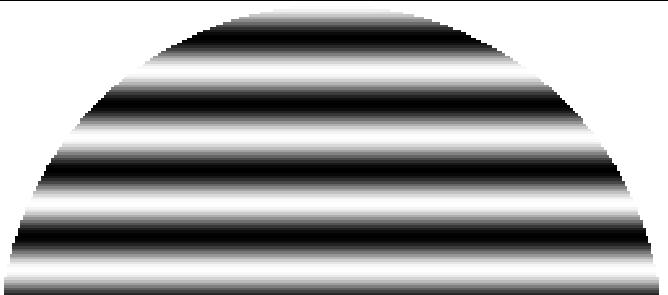
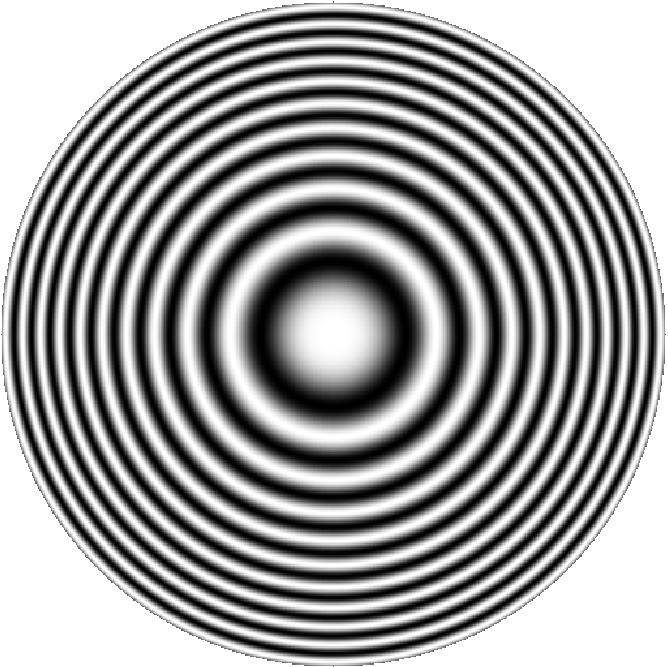
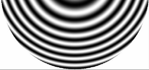
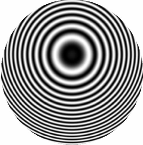
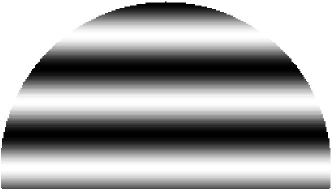
1 Why is There a Black Dot when Defocus = 1λ? W = W 020 = a 020 ρ 2 When a 020 = 1λ Sag of the wavefront at full aperture (ρ = 1) = 1λ Sag of the wavefront at ρ = = 0.5λ Area of the pupil from ρ = 0 to ρ = equals area of annular pupil from ρ = to ρ = 1.0 Therefore, for every point within r = 0.707, there is a point in annulus that is λ/2 out of phase Consequently, on-axis everything cancels! No light! Black Dot! Spring


2 The Black Dot When a perfect circular wavefront is defocused exactly 1λ, a black dot appears at the center of the spot Find the ±1λplanes, then split the difference for sharp focusing Spring
3 Longitudinal Magnification First what is transverse magnification? M = L 2 /L 1 Longitudinal Magnification is simple. If we move the object along the axis by an amount, DZ, the image will move DZ' Longitudinal Magnification is defined as: M L = Z Z It can be shown that M L = M 2 So what? It is useful for measuring despacing sensitivities of optical components. It is also why your nose looks so big on a doorknob! Spring
4 The Usefulness of Depth of Focus and Longitudinal Magnification Formulas (example) Problem: Find the spacing tolerance between the primary and secondary mirror of a diffraction limited, F/10 Cassegrain telescope. The primary mirror is F/2, the telescope is used in the visible (λ = 0.5µ). M = F/10 F/ 2 = 5 1. The diffraction limited (λ/4) depth of focus at the large image plane of the Cassegrain is given by f = ± F/# 2 (in microns) (when λ = 0.5µ) = ± 100 microns 2. The secondary mirror converts an F/2 beam into an F/10 beam. Thus, the magnification of the secondary mirror is 3. The longitudinal magnification M L = M 2 = 5 2 = A 100µ change in focus will occur if S changes by 100/25 = 4µ = spacing tolerance Spring
5 Interferometer: Optical Testing Tool An interferometer compares a wavefront reflected off a test component with that reflected from a well-known and perfect (to required tolerances) reference component (usually a flat mirror); The wavefronts are derived from a single input wavefront via a beamsplitter; The two wavefrontsinterfere; any errors in the test piece create optical path differences (relative to the test component) that show up as interference fringes in the interferometer output; Note: 1 fringe represents an optical path difference of 1 wavelength between the test and reference wavefronts; Typically, a laser is used as the light source. If the laser is single-mode (long coherence length), then the test and reference arms may be of significantly different lengths Laser Unequal Path Interferometer (LUPI). beamsplitter Test arm Reference arm Input wavefront Output: two interfering wavefronts Spring
6 OPD for Surface Defects, Refractive t n air OPD wavefront interface OPD ( n ) t = 1 Surface defects cause wavefront errors and therefore a degradation of the image quality; At a glass (index n) to air interface, a bump in the surface causes a dip in the wavefront (light is faster in air): For typical optical glass (n=1.5), OPD = 0.5t However, for infrared materials (e.g. Ge, n=4), OPD = 3t!! Thus, surface quality specs must be tighter in the infrared than in the visible. But this is mitigated by the wavelength being longer! Spring
7 OPD for Surface Defects, Reflective OPD t Incident wavefront reflected wavefront mirror The effective index of a mirror in air is -1; At a mirror surface, a dip in the surface causes a dip in the wavefront: Thus, OPD = -2t!! Thus, surface quality specs must be fairly tight for mirrors; comparison with infrared materials depends on the material. OPD ( n ) t = 1 Spring


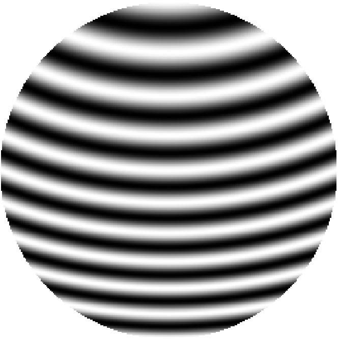
8 5λ A 011 =?λ 10λ Tilt between the two plane wavefronts Spring


9 Spring = + = + = 40
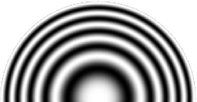
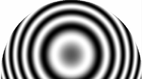
10 Spherical Aberration Granddaddy of all aberrations Mathematically: W = W 040 = a 040 ρ4 Interferometrically: Concentric rings (similar to defocus). However the number increases as ρ 4 Can be minimized by adding defocus Star Test Very Interesting Rays from different annuli or "zones" have different focal points Has very characteristic "thru focus" pattern Unlike defocus, "black dot" is not visible, even for small amounts of spherical aberration Spring

11 Spherical Aberration (Best Focus) Zernike polynomial R 0 4 Spring
 Spring")
12 Spherical Aberration (Best Focus) Spring

13 Spherical Aberration(Marginal Focus) Spring
14 Spherical Aberration (Paraxial Focus) Spring


15 Paraxial Focus Mid Focus Marginal Focus No Aberration, Focal Shift Small Spherical Aberration Larger Spherical Aberration Spring
 Spring 2018")
16 A Parabolic Mirror and its Caustic Surface (Due to Spherical Aberration) Spring

17 Details of the Spherical Aberration Caustic Spring


18 The inner & outer caustic Spring
19 Spherical Aberration Spring


20 Spherical Aberration Blur (Star Test) At paraxial focus, a pronounced halo surrounds Airy disk At marginal focus, little energy is in core but a bright annulus is visible Spring
")
21 Thru Focus Spherical Aberration (Star Test) Spring
22 Causes of (Extraneous) Spherical Aberration How can spherical aberration indicate the presence of misalignments or other errors? Lens is reversed Spacing error between lenses Optical surface radius incorrect Wrong aspheric Null test error (Think Hubble Space Telescope) Aspheric coefficient sign flip Pupil diameter error Wrong glass material Spring
Cardinal Points of an Optical System--and Other Basic Facts
 Cardinal Points of an Optical System--and Other Basic Facts The fundamental feature of any optical system is the aperture stop. Thus, the most fundamental optical system is the pinhole camera. The image
3.0 Alignment Equipment and Diagnostic Tools:
 3.0 Alignment Equipment and Diagnostic Tools: Alignment equipment The alignment telescope and its use The laser autostigmatic cube (LACI) interferometer A pin -- and how to find the center of curvature
Lecture 2: Geometrical Optics. Geometrical Approximation. Lenses. Mirrors. Optical Systems. Images and Pupils. Aberrations.
 Lecture 2: Geometrical Optics Outline 1 Geometrical Approximation 2 Lenses 3 Mirrors 4 Optical Systems 5 Images and Pupils 6 Aberrations Christoph U. Keller, Leiden Observatory, keller@strw.leidenuniv.nl
Lecture 4: Geometrical Optics 2. Optical Systems. Images and Pupils. Rays. Wavefronts. Aberrations. Outline
 Lecture 4: Geometrical Optics 2 Outline 1 Optical Systems 2 Images and Pupils 3 Rays 4 Wavefronts 5 Aberrations Christoph U. Keller, Leiden University, keller@strw.leidenuniv.nl Lecture 4: Geometrical
Lecture 2: Geometrical Optics. Geometrical Approximation. Lenses. Mirrors. Optical Systems. Images and Pupils. Aberrations.
 Lecture 2: Geometrical Optics Outline 1 Geometrical Approximation 2 Lenses 3 Mirrors 4 Optical Systems 5 Images and Pupils 6 Aberrations Christoph U. Keller, Leiden Observatory, keller@strw.leidenuniv.nl
Computer Generated Holograms for Optical Testing
 Computer Generated Holograms for Optical Testing Dr. Jim Burge Associate Professor Optical Sciences and Astronomy University of Arizona jburge@optics.arizona.edu 520-621-8182 Computer Generated Holograms
OPTICAL IMAGING AND ABERRATIONS
 OPTICAL IMAGING AND ABERRATIONS PARTI RAY GEOMETRICAL OPTICS VIRENDRA N. MAHAJAN THE AEROSPACE CORPORATION AND THE UNIVERSITY OF SOUTHERN CALIFORNIA SPIE O P T I C A L E N G I N E E R I N G P R E S S A
Reflectors vs. Refractors
 1 Telescope Types - Telescopes collect and concentrate light (which can then be magnified, dispersed as a spectrum, etc). - In the end it is the collecting area that counts. - There are two primary telescope
EE119 Introduction to Optical Engineering Fall 2009 Final Exam. Name:
 EE119 Introduction to Optical Engineering Fall 2009 Final Exam Name: SID: CLOSED BOOK. THREE 8 1/2 X 11 SHEETS OF NOTES, AND SCIENTIFIC POCKET CALCULATOR PERMITTED. TIME ALLOTTED: 180 MINUTES Fundamental
Mirrors and Lenses. Images can be formed by reflection from mirrors. Images can be formed by refraction through lenses.
 Mirrors and Lenses Images can be formed by reflection from mirrors. Images can be formed by refraction through lenses. Notation for Mirrors and Lenses The object distance is the distance from the object
APPLICATION NOTE
 THE PHYSICS BEHIND TAG OPTICS TECHNOLOGY AND THE MECHANISM OF ACTION OF APPLICATION NOTE 12-001 USING SOUND TO SHAPE LIGHT Page 1 of 6 Tutorial on How the TAG Lens Works This brief tutorial explains the
Geometric optics & aberrations
 Geometric optics & aberrations Department of Astrophysical Sciences University AST 542 http://www.northerneye.co.uk/ Outline Introduction: Optics in astronomy Basics of geometric optics Paraxial approximation
J. C. Wyant Fall, 2012 Optics Optical Testing and Testing Instrumentation
 J. C. Wyant Fall, 2012 Optics 513 - Optical Testing and Testing Instrumentation Introduction 1. Measurement of Paraxial Properties of Optical Systems 1.1 Thin Lenses 1.1.1 Measurements Based on Image Equation
Exercise 8: Interference and diffraction
 Physics 223 Name: Exercise 8: Interference and diffraction 1. In a two-slit Young s interference experiment, the aperture (the mask with the two slits) to screen distance is 2.0 m, and a red light of wavelength
Modulation Transfer Function
 Modulation Transfer Function The Modulation Transfer Function (MTF) is a useful tool in system evaluation. t describes if, and how well, different spatial frequencies are transferred from object to image.
Lens Design I. Lecture 5: Advanced handling I Herbert Gross. Summer term
 Lens Design I Lecture 5: Advanced handling I 2018-05-17 Herbert Gross Summer term 2018 www.iap.uni-jena.de 2 Preliminary Schedule - Lens Design I 2018 1 12.04. Basics 2 19.04. Properties of optical systems
EE119 Introduction to Optical Engineering Spring 2003 Final Exam. Name:
 EE119 Introduction to Optical Engineering Spring 2003 Final Exam Name: SID: CLOSED BOOK. THREE 8 1/2 X 11 SHEETS OF NOTES, AND SCIENTIFIC POCKET CALCULATOR PERMITTED. TIME ALLOTTED: 180 MINUTES Fundamental
Long Wave Infrared Scan Lens Design And Distortion Correction
 Long Wave Infrared Scan Lens Design And Distortion Correction Item Type text; Electronic Thesis Authors McCarron, Andrew Publisher The University of Arizona. Rights Copyright is held by the author. Digital
PHY 431 Homework Set #5 Due Nov. 20 at the start of class
 PHY 431 Homework Set #5 Due Nov. 0 at the start of class 1) Newton s rings (10%) The radius of curvature of the convex surface of a plano-convex lens is 30 cm. The lens is placed with its convex side down
ECEG105/ECEU646 Optics for Engineers Course Notes Part 4: Apertures, Aberrations Prof. Charles A. DiMarzio Northeastern University Fall 2008
 ECEG105/ECEU646 Optics for Engineers Course Notes Part 4: Apertures, Aberrations Prof. Charles A. DiMarzio Northeastern University Fall 2008 July 2003+ Chuck DiMarzio, Northeastern University 11270-04-1
Performance Factors. Technical Assistance. Fundamental Optics
 Performance Factors After paraxial formulas have been used to select values for component focal length(s) and diameter(s), the final step is to select actual lenses. As in any engineering problem, this
The Design, Fabrication, and Application of Diamond Machined Null Lenses for Testing Generalized Aspheric Surfaces
 The Design, Fabrication, and Application of Diamond Machined Null Lenses for Testing Generalized Aspheric Surfaces James T. McCann OFC - Diamond Turning Division 69T Island Street, Keene New Hampshire
Waves & Oscillations
 Physics 42200 Waves & Oscillations Lecture 33 Geometric Optics Spring 2013 Semester Matthew Jones Aberrations We have continued to make approximations: Paraxial rays Spherical lenses Index of refraction
Use of Computer Generated Holograms for Testing Aspheric Optics
 Use of Computer Generated Holograms for Testing Aspheric Optics James H. Burge and James C. Wyant Optical Sciences Center, University of Arizona, Tucson, AZ 85721 http://www.optics.arizona.edu/jcwyant,
Study on Imaging Quality of Water Ball Lens
 2017 2nd International Conference on Mechatronics and Information Technology (ICMIT 2017) Study on Imaging Quality of Water Ball Lens Haiyan Yang1,a,*, Xiaopan Li 1,b, 1,c Hao Kong, 1,d Guangyang Xu and1,eyan
Testing Aspheric Lenses: New Approaches
 Nasrin Ghanbari OPTI 521 - Synopsis of a published Paper November 5, 2012 Testing Aspheric Lenses: New Approaches by W. Osten, B. D orband, E. Garbusi, Ch. Pruss, and L. Seifert Published in 2010 Introduction
Image Formation. Light from distant things. Geometrical optics. Pinhole camera. Chapter 36
 Light from distant things Chapter 36 We learn about a distant thing from the light it generates or redirects. The lenses in our eyes create images of objects our brains can process. This chapter concerns
Lecture 3: Geometrical Optics 1. Spherical Waves. From Waves to Rays. Lenses. Chromatic Aberrations. Mirrors. Outline
 Lecture 3: Geometrical Optics 1 Outline 1 Spherical Waves 2 From Waves to Rays 3 Lenses 4 Chromatic Aberrations 5 Mirrors Christoph U. Keller, Leiden Observatory, keller@strw.leidenuniv.nl Lecture 3: Geometrical
GEOMETRICAL OPTICS AND OPTICAL DESIGN
 GEOMETRICAL OPTICS AND OPTICAL DESIGN Pantazis Mouroulis Associate Professor Center for Imaging Science Rochester Institute of Technology John Macdonald Senior Lecturer Physics Department University of
Chapter Ray and Wave Optics
 109 Chapter Ray and Wave Optics 1. An astronomical telescope has a large aperture to [2002] reduce spherical aberration have high resolution increase span of observation have low dispersion. 2. If two
Solution of Exercises Lecture Optical design with Zemax for PhD Part 8
 2013-06-17 Prof. Herbert Gross Friedrich Schiller University Jena Institute of Applied Physics Albert-Einstein-Str 15 07745 Jena Solution of Exercises Lecture Optical design with Zemax for PhD Part 8 8.1
Exercises Advanced Optical Design Part 5 Solutions
 2014-12-09 Manuel Tessmer M.Tessmer@uni-jena.dee Minyi Zhong minyi.zhong@uni-jena.de Herbert Gross herbert.gross@uni-jena.de Friedrich Schiller University Jena Institute of Applied Physics Albert-Einstein-Str.
Physics 431 Final Exam Examples (3:00-5:00 pm 12/16/2009) TIME ALLOTTED: 120 MINUTES Name: Signature:
 TIME ALLOTTED: 120 MINUTES Name: Signature:") Physics 431 Final Exam Examples (3:00-5:00 pm 12/16/2009) TIME ALLOTTED: 120 MINUTES Name: PID: Signature: CLOSED BOOK. TWO 8 1/2 X 11 SHEET OF NOTES (double sided is allowed), AND SCIENTIFIC POCKET CALCULATOR
Physics 431 Final Exam Examples (3:00-5:00 pm 12/16/2009) TIME ALLOTTED: 120 MINUTES Name: PID: Signature: CLOSED BOOK. TWO 8 1/2 X 11 SHEET OF NOTES (double sided is allowed), AND SCIENTIFIC POCKET CALCULATOR
Lens Design I Seminar 5
 Y. Sekman, X. Lu, H. Gross Friedrich Schiller University Jena Institute of Applied Physics Albert-Einstein-Str 15 07745 Jena Lens Design I Seminar 5 Exercise 5-1: PSF scaling (Homework) To check the Airy
EE119 Introduction to Optical Engineering Spring 2002 Final Exam. Name:
 EE119 Introduction to Optical Engineering Spring 2002 Final Exam Name: SID: CLOSED BOOK. FOUR 8 1/2 X 11 SHEETS OF NOTES, AND SCIENTIFIC POCKET CALCULATOR PERMITTED. TIME ALLOTTED: 180 MINUTES Fundamental
 Telecentric Imaging Object space telecentricity stop source: edmund optics The 5 classical Seidel Aberrations First order aberrations Spherical Aberration (~r 4 ) Origin: different focal lengths for different
ECEN 4606, UNDERGRADUATE OPTICS LAB
 ECEN 4606, UNDERGRADUATE OPTICS LAB Lab 2: Imaging 1 the Telescope Original Version: Prof. McLeod SUMMARY: In this lab you will become familiar with the use of one or more lenses to create images of distant
INTRODUCTION TO ABERRATIONS IN OPTICAL IMAGING SYSTEMS
 INTRODUCTION TO ABERRATIONS IN OPTICAL IMAGING SYSTEMS JOSE SASIÄN University of Arizona ШШ CAMBRIDGE Щ0 UNIVERSITY PRESS Contents Preface Acknowledgements Harold H. Hopkins Roland V. Shack Symbols 1 Introduction
Diffraction. Interference with more than 2 beams. Diffraction gratings. Diffraction by an aperture. Diffraction of a laser beam
 Diffraction Interference with more than 2 beams 3, 4, 5 beams Large number of beams Diffraction gratings Equation Uses Diffraction by an aperture Huygen s principle again, Fresnel zones, Arago s spot Qualitative
Solution of Exercises Lecture Optical design with Zemax Part 6
 2013-06-17 Prof. Herbert Gross Friedrich Schiller University Jena Institute of Applied Physics Albert-Einstein-Str 15 07745 Jena Solution of Exercises Lecture Optical design with Zemax Part 6 6 Illumination
Advanced Lens Design
 Advanced Lens Design Lecture 3: Aberrations I 214-11-4 Herbert Gross Winter term 214 www.iap.uni-jena.de 2 Preliminary Schedule 1 21.1. Basics Paraxial optics, imaging, Zemax handling 2 28.1. Optical systems
Lens Design I. Lecture 3: Properties of optical systems II Herbert Gross. Summer term
 Lens Design I Lecture 3: Properties of optical systems II 205-04-8 Herbert Gross Summer term 206 www.iap.uni-jena.de 2 Preliminary Schedule 04.04. Basics 2.04. Properties of optical systrems I 3 8.04.
Supplemental Materials. Section 25. Aberrations
 OTI-201/202 Geometrical and Instrumental Optics 25-1 Supplemental Materials Section 25 Aberrations Aberrations of the Rotationally Symmetric Optical System First-order or paraxial systems are ideal optical
Exam Preparation Guide Geometrical optics (TN3313)
") Exam Preparation Guide Geometrical optics (TN3313) Lectures: September - December 2001 Version of 21.12.2001 When preparing for the exam, check on Blackboard for a possible newer version of this guide.
Exam Preparation Guide Geometrical optics (TN3313) Lectures: September - December 2001 Version of 21.12.2001 When preparing for the exam, check on Blackboard for a possible newer version of this guide.
Introduction to Optical Modeling. Friedrich-Schiller-University Jena Institute of Applied Physics. Lecturer: Prof. U.D. Zeitner
 Introduction to Optical Modeling Friedrich-Schiller-University Jena Institute of Applied Physics Lecturer: Prof. U.D. Zeitner The Nature of Light Fundamental Question: What is Light? Newton Huygens / Maxwell
Lecture 8. Lecture 8. r 1
 Lecture 8 Achromat Design Design starts with desired Next choose your glass materials, i.e. Find P D P D, then get f D P D K K Choose radii (still some freedom left in choice of radii for minimization
Optics of Wavefront. Austin Roorda, Ph.D. University of Houston College of Optometry
 Optics of Wavefront Austin Roorda, Ph.D. University of Houston College of Optometry Geometrical Optics Relationships between pupil size, refractive error and blur Optics of the eye: Depth of Focus 2 mm
LECTURE 13 DIFFRACTION. Instructor: Kazumi Tolich
 LECTURE 13 DIFFRACTION Instructor: Kazumi Tolich Lecture 13 2 Reading chapter 33-4 & 33-6 to 33-7 Single slit diffraction Two slit interference-diffraction Fraunhofer and Fresnel diffraction Diffraction
Exam 4. Name: Class: Date: Multiple Choice Identify the choice that best completes the statement or answers the question.
 Name: Class: Date: Exam 4 Multiple Choice Identify the choice that best completes the statement or answers the question. 1. Mirages are a result of which physical phenomena a. interference c. reflection
Testing Aspherics Using Two-Wavelength Holography
 Reprinted from APPLIED OPTICS. Vol. 10, page 2113, September 1971 Copyright 1971 by the Optical Society of America and reprinted by permission of the copyright owner Testing Aspherics Using Two-Wavelength
R.B.V.R.R. WOMEN S COLLEGE (AUTONOMOUS) Narayanaguda, Hyderabad.
 Narayanaguda, Hyderabad.") R.B.V.R.R. WOMEN S COLLEGE (AUTONOMOUS) Narayanaguda, Hyderabad. DEPARTMENT OF PHYSICS QUESTION BANK FOR SEMESTER III PAPER III OPTICS UNIT I: 1. MATRIX METHODS IN PARAXIAL OPTICS 2. ABERATIONS UNIT II
R.B.V.R.R. WOMEN S COLLEGE (AUTONOMOUS) Narayanaguda, Hyderabad. DEPARTMENT OF PHYSICS QUESTION BANK FOR SEMESTER III PAPER III OPTICS UNIT I: 1. MATRIX METHODS IN PARAXIAL OPTICS 2. ABERATIONS UNIT II
Tutorial Zemax 8: Correction II
 Tutorial Zemax 8: Correction II 2012-10-11 8 Correction II 1 8.1 High-NA Collimator... 1 8.2 Zoom-System... 6 8.3 New Achromate and wide field system... 11 8 Correction II 8.1 High-NA Collimator An achromatic
BEAM HALO OBSERVATION BY CORONAGRAPH
 BEAM HALO OBSERVATION BY CORONAGRAPH T. Mitsuhashi, KEK, TSUKUBA, Japan Abstract We have developed a coronagraph for the observation of the beam halo surrounding a beam. An opaque disk is set in the beam
Basic Wavefront Aberration Theory for Optical Metrology
 APPLIED OPTICS AND OPTICAL ENGINEERING, VOL. Xl CHAPTER 1 Basic Wavefront Aberration Theory for Optical Metrology JAMES C. WYANT Optical Sciences Center, University of Arizona and WYKO Corporation, Tucson,
USE OF COMPUTER- GENERATED HOLOGRAMS IN OPTICAL TESTING
 14 USE OF COMPUTER- GENERATED HOLOGRAMS IN OPTICAL TESTING Katherine Creath College of Optical Sciences University of Arizona Tucson, Arizona Optineering Tucson, Arizona James C. Wyant College of Optical
Chapter 23. Mirrors and Lenses
 Chapter 23 Mirrors and Lenses Mirrors and Lenses The development of mirrors and lenses aided the progress of science. It led to the microscopes and telescopes. Allowed the study of objects from microbes
Explanation of Aberration and Wavefront
 Explanation of Aberration and Wavefront 1. What Causes Blur? 2. What is? 4. What is wavefront? 5. Hartmann-Shack Aberrometer 6. Adoption of wavefront technology David Oh 1. What Causes Blur? 2. What is?
OPTICS DIVISION B. School/#: Names:
 OPTICS DIVISION B School/#: Names: Directions: Fill in your response for each question in the space provided. All questions are worth two points. Multiple Choice (2 points each question) 1. Which of the
Exercise 1 - Lens bending
 Exercise 1 - Lens bending Most of the aberrations change with the bending of a lens. This is demonstrated in this exercise. a) Establish a lens with focal length f = 100 mm made of BK7 with thickness 5
Optical Systems: Pinhole Camera Pinhole camera: simple hole in a box: Called Camera Obscura Aristotle discussed, Al-Hazen analyzed in Book of Optics
 Optical Systems: Pinhole Camera Pinhole camera: simple hole in a box: Called Camera Obscura Aristotle discussed, Al-Hazen analyzed in Book of Optics 1011CE Restricts rays: acts as a single lens: inverts
Exam 3--PHYS 102--S10
 ame: Exam 3--PHYS 02--S0 Multiple Choice Identify the choice that best completes the statement or answers the question.. At an intersection of hospital hallways, a convex mirror is mounted high on a wall
Chapter 25. Optical Instruments
 Chapter 25 Optical Instruments Optical Instruments Analysis generally involves the laws of reflection and refraction Analysis uses the procedures of geometric optics To explain certain phenomena, the wave
Simulation of Zernike Aberrations in optical systems. Michael Koch, July 5, 2018
 Simulation of Zernike Aberrations in optical systems Michael Koch, astroelectronic@t-online.de July 5, 2018 This paper is about three related questions: 1. In a Newton telescope we have two mirrors. It's
The following article is a translation of parts of the original publication of Karl-Ludwig Bath in the german astronomical magazine:
 The following article is a translation of parts of the original publication of Karl-Ludwig Bath in the german astronomical magazine: Sterne und Weltraum 1973/6, p.177-180. The publication of this translation
Lens Design I. Lecture 3: Properties of optical systems II Herbert Gross. Summer term
 Lens Design I Lecture 3: Properties of optical systems II 207-04-20 Herbert Gross Summer term 207 www.iap.uni-jena.de 2 Preliminary Schedule - Lens Design I 207 06.04. Basics 2 3.04. Properties of optical
OPTINO. SpotOptics VERSATILE WAVEFRONT SENSOR O P T I N O
 Spotptics he software people for optics VERSALE WAVEFR SESR Accurate metrology in single and double pass Lenses, mirrors and laser beams Any focal length and diameter Large dynamic range Adaptable for
Big League Cryogenics and Vacuum The LHC at CERN
 Big League Cryogenics and Vacuum The LHC at CERN A typical astronomical instrument must maintain about one cubic meter at a pressure of
Optical Design with Zemax
 Optical Design with Zemax Lecture : Correction II 3--9 Herbert Gross Summer term www.iap.uni-jena.de Correction II Preliminary time schedule 6.. Introduction Introduction, Zemax interface, menues, file
Laboratory experiment aberrations
 Laboratory experiment aberrations Obligatory laboratory experiment on course in Optical design, SK2330/SK3330, KTH. Date Name Pass Objective This laboratory experiment is intended to demonstrate the most
Opti 415/515. Introduction to Optical Systems. Copyright 2009, William P. Kuhn
 Opti 415/515 Introduction to Optical Systems 1 Optical Systems Manipulate light to form an image on a detector. Point source microscope Hubble telescope (NASA) 2 Fundamental System Requirements Application
MASSACHUSETTS INSTITUTE OF TECHNOLOGY Mechanical Engineering Department. 2.71/2.710 Final Exam. May 21, Duration: 3 hours (9 am-12 noon)
") MASSACHUSETTS INSTITUTE OF TECHNOLOGY Mechanical Engineering Department 2.71/2.710 Final Exam May 21, 2013 Duration: 3 hours (9 am-12 noon) CLOSED BOOK Total pages: 5 Name: PLEASE RETURN THIS BOOKLET WITH
MASSACHUSETTS INSTITUTE OF TECHNOLOGY Mechanical Engineering Department 2.71/2.710 Final Exam May 21, 2013 Duration: 3 hours (9 am-12 noon) CLOSED BOOK Total pages: 5 Name: PLEASE RETURN THIS BOOKLET WITH
Exam questions OPTI 517. Only a calculator and a single sheet of paper, 8 X11, with formulas will be allowed during the exam.
 Exam questions OPTI 517 Only a calculator an a single sheet of paper, 8 X11, with formulas will be allowe uring the exam. 1) A single optical spherical surface oes not contribute spherical aberration.
PROCEEDINGS OF SPIE. Measurement of low-order aberrations with an autostigmatic microscope
 PROCEEDINGS OF SPIE SPIEDigitalLibrary.org/conference-proceedings-of-spie Measurement of low-order aberrations with an autostigmatic microscope William P. Kuhn Measurement of low-order aberrations with
The predicted performance of the ACS coronagraph
 Instrument Science Report ACS 2000-04 The predicted performance of the ACS coronagraph John Krist March 30, 2000 ABSTRACT The Aberrated Beam Coronagraph (ABC) on the Advanced Camera for Surveys (ACS) has
Contouring aspheric surfaces using two-wavelength phase-shifting interferometry
 OPTICA ACTA, 1985, VOL. 32, NO. 12, 1455-1464 Contouring aspheric surfaces using two-wavelength phase-shifting interferometry KATHERINE CREATH, YEOU-YEN CHENG and JAMES C. WYANT University of Arizona,
Chapter 36: diffraction
 Chapter 36: diffraction Fresnel and Fraunhofer diffraction Diffraction from a single slit Intensity in the single slit pattern Multiple slits The Diffraction grating X-ray diffraction Circular apertures
Chapter 34 The Wave Nature of Light; Interference. Copyright 2009 Pearson Education, Inc.
 Chapter 34 The Wave Nature of Light; Interference 34-7 Luminous Intensity The intensity of light as perceived depends not only on the actual intensity but also on the sensitivity of the eye at different
Introductions to aberrations OPTI 517
 Introductions to aberrations OPTI 517 Lecture 11 Spherical aberration Meridional and sagittal ray fans Spherical aberration 0.25 wave f/10; f=100 mm; wave=0.0005 mm Spherical aberration 0.5 wave f/10;
VATT Optical Performance During 98 Oct as Measured with an Interferometric Hartmann Wavefront Sensor
 VATT Optical Performance During 98 Oct as Measured with an Interferometric Hartmann Wavefront Sensor S. C. West, D. Fisher Multiple Mirror Telescope Observatory M. Nelson Vatican Advanced Technology Telescope
Binocular and Scope Performance 57. Diffraction Effects
 Binocular and Scope Performance 57 Diffraction Effects The resolving power of a perfect optical system is determined by diffraction that results from the wave nature of light. An infinitely distant point
Potential benefits of freeform optics for the ELT instruments. J. Kosmalski
 Potential benefits of freeform optics for the ELT instruments J. Kosmalski Freeform Days, 12-13 th October 2017 Summary Introduction to E-ELT intruments Freeform design for MAORY LGS Free form design for
1.1 Singlet. Solution. a) Starting setup: The two radii and the image distance is chosen as variable.
 Starting setup: The two radii and the image distance is chosen as variable.") 1 1.1 Singlet Optimize a single lens with the data λ = 546.07 nm, object in the distance 100 mm from the lens on axis only, focal length f = 45 mm and numerical aperture NA = 0.07 in the object space.
1 1.1 Singlet Optimize a single lens with the data λ = 546.07 nm, object in the distance 100 mm from the lens on axis only, focal length f = 45 mm and numerical aperture NA = 0.07 in the object space.
12.4 Alignment and Manufacturing Tolerances for Segmented Telescopes
 330 Chapter 12 12.4 Alignment and Manufacturing Tolerances for Segmented Telescopes Similar to the JWST, the next-generation large-aperture space telescope for optical and UV astronomy has a segmented
Chapter 23. Mirrors and Lenses
 Chapter 23 Mirrors and Lenses Notation for Mirrors and Lenses The object distance is the distance from the object to the mirror or lens Denoted by p The image distance is the distance from the image to
Reflection! Reflection and Virtual Image!
 1/30/14 Reflection - wave hits non-absorptive surface surface of a smooth water pool - incident vs. reflected wave law of reflection - concept for all electromagnetic waves - wave theory: reflected back
Puntino. Shack-Hartmann wavefront sensor for optimizing telescopes. The software people for optics
 Puntino Shack-Hartmann wavefront sensor for optimizing telescopes 1 1. Optimize telescope performance with a powerful set of tools A finely tuned telescope is the key to obtaining deep, high-quality astronomical
Geometrical Optics for AO Claire Max UC Santa Cruz CfAO 2009 Summer School
 Geometrical Optics for AO Claire Max UC Santa Cruz CfAO 2009 Summer School Page 1 Some tools for active learning In-class conceptual questions will aim to engage you in more active learning and provide
COURSE NAME: PHOTOGRAPHY AND AUDIO VISUAL PRODUCTION (VOCATIONAL) FOR UNDER GRADUATE (FIRST YEAR)
 FOR UNDER GRADUATE (FIRST YEAR)") COURSE NAME: PHOTOGRAPHY AND AUDIO VISUAL PRODUCTION (VOCATIONAL) FOR UNDER GRADUATE (FIRST YEAR) PAPER TITLE: BASIC PHOTOGRAPHIC UNIT - 3 : SIMPLE LENS TOPIC: LENS PROPERTIES AND DEFECTS OBJECTIVES By
COURSE NAME: PHOTOGRAPHY AND AUDIO VISUAL PRODUCTION (VOCATIONAL) FOR UNDER GRADUATE (FIRST YEAR) PAPER TITLE: BASIC PHOTOGRAPHIC UNIT - 3 : SIMPLE LENS TOPIC: LENS PROPERTIES AND DEFECTS OBJECTIVES By
PHYSICS. Chapter 35 Lecture FOR SCIENTISTS AND ENGINEERS A STRATEGIC APPROACH 4/E RANDALL D. KNIGHT
 PHYSICS FOR SCIENTISTS AND ENGINEERS A STRATEGIC APPROACH 4/E Chapter 35 Lecture RANDALL D. KNIGHT Chapter 35 Optical Instruments IN THIS CHAPTER, you will learn about some common optical instruments and
Optical System Design
 Phys 531 Lecture 12 14 October 2004 Optical System Design Last time: Surveyed examples of optical systems Today, discuss system design Lens design = course of its own (not taught by me!) Try to give some
Practice Problems for Chapter 25-26
 Practice Problems for Chapter 25-26 1. What are coherent waves? 2. Describe diffraction grating 3. What are interference fringes? 4. What does monochromatic light mean? 5. What does the Rayleigh Criterion
Fiber Optic Communications
 Fiber Optic Communications ( Chapter 2: Optics Review ) presented by Prof. Kwang-Chun Ho 1 Section 2.4: Numerical Aperture Consider an optical receiver: where the diameter of photodetector surface area
NON-NULL INTERFEROMETER FOR TESTING OF ASPHERIC SURFACES. John J. Sullivan. A Dissertation Submitted to the Faculty of the COLLEGE OF OPTICAL SCIENCES
 NON-NULL INTERFEROMETER FOR TESTING OF ASPHERIC SURFACES by John J. Sullivan A Dissertation Submitted to the Faculty of the COLLEGE OF OPTICAL SCIENCES In Partial Fulfillment of the Requirements For the
Collimation Tester Instructions
 Description Use shear-plate collimation testers to examine and adjust the collimation of laser light, or to measure the wavefront curvature and divergence/convergence magnitude of large-radius optical
Curved Surface Testing
 08CurvedSurfaceTesting.nb Optics 513 - James C. Wyant (2013) 1 Curved Surface Testing CS-1 The interferogram shown below was obtained using the Twyman-Green interferometer to test a cheap camera lens in
Design of null lenses for testing of elliptical surfaces
 Design of null lenses for testing of elliptical surfaces Yeon Soo Kim, Byoung Yoon Kim, and Yun Woo Lee Null lenses are designed for testing the oblate elliptical surface that is the third mirror of the
Magnification, stops, mirrors More geometric optics
 Magnification, stops, mirrors More geometric optics D. Craig 2005-02-25 Transverse magnification Refer to figure 5.22. By convention, distances above the optical axis are taken positive, those below, negative.
Lens Design I. Lecture 5: Advanced handling I Herbert Gross. Summer term
 Lens Design I Lecture 5: Advanced handling I 2015-05-11 Herbert Gross Summer term 2015 www.iap.uni-jena.de 2 Preliminary Schedule 1 13.04. Basics 2 20.04. Properties of optical systrems I 3 27.05. Properties
Chapter 25 Optical Instruments
 Chapter 25 Optical Instruments Units of Chapter 25 Cameras, Film, and Digital The Human Eye; Corrective Lenses Magnifying Glass Telescopes Compound Microscope Aberrations of Lenses and Mirrors Limits of
INTRODUCTION THIN LENSES. Introduction. given by the paraxial refraction equation derived last lecture: Thin lenses (19.1) = 1. Double-lens systems
 = 1. Double-lens systems") Chapter 9 OPTICAL INSTRUMENTS Introduction Thin lenses Double-lens systems Aberrations Camera Human eye Compound microscope Summary INTRODUCTION Knowledge of geometrical optics, diffraction and interference,
Chapter 9 OPTICAL INSTRUMENTS Introduction Thin lenses Double-lens systems Aberrations Camera Human eye Compound microscope Summary INTRODUCTION Knowledge of geometrical optics, diffraction and interference,