CHAPTER TWO METALLOGRAPHY & MICROSCOPY
|
|
|
- Imogen Lee
- 6 years ago
- Views:
Transcription
 the structure")
1 CHAPTER TWO METALLOGRAPHY & MICROSCOPY 1. INTRODUCTION: Materials characterisation has two main aspects: Accurately measuring the physical, mechanical and chemical properties of materials Accurately measuring (determining) the structure of a material Atomic level structures Microscopic level structures A critical part of materials science & technology is to seek relationships between: 1
2 STRUCTURE PROPERTIES PERFORMANCE PROCESSING Performance is the ultimate end use function of the material and is the result from a proper set of properties achieved by optimising both atomic level and microstructural levels of the structure of the material prepared and fabricated using carefully controlled and optimised processing techniques. What is metallography (Materiallography)? The study of structure of materials It includes the techniques used to: Prepare specimens for examination, Examine the specimens and Interpreting the structures. What is a microstructure? Most engineering materials of great importance are based on metals, they are crystalline in the solid form. 2
3 Metals also are normally polycrystalline, meaning they consist of many small crystals, called grains. In some cases, these grains can be viewed with the naked eye and these structures are called MACROSTRUCTURES The structural features of small grains are observed using an optical microscope, or an electron microscope. These structures are called MICROSTRUCTURES. The structural features present in a material are a function of the composition and form of the starting material, and any subsequent heat treatment and /or processing treatment the material receives. Microstructural analysis is used to provide information on how the material was produced and the quality of the resulting material. Microstructural features, which are of great concern to us include: grain size, phase volume fraction, precipitate size, defects (porosity and cracks) 3


.")

4 What is Microstructural Analysis used for? Macrostructural and Microstructural examination techniques are used in areas such as: Quality Control: Analysis is used to determine whether the structural parameters are within specifications: a criteria for ACCEPTANCE or REJECTION of products Failure Analysis: to determine the cause of failure. Failure occur due to several factors (incorrect material selection, improper processing treatment, poor quality control).failure analysis provides information about the cause of failure Research Studies: is used to determine the microstructural changes that occur as a result of varying parameters such as composition, heat treatment or processing. The research studies develop the PROCESSING - STRUCTURE - PROPERTIES relationships. What Information can be Observed Quality of specimen preparation is a determining factor in the value of examination Effect of cold work 4

5 SPECIMEN PREPARATION Specimen preparation is an important part of metallography A specimen must be appropriately prepared to ensure correct observation and interpretation of the microstructure. Specimen preparation requirements Deformation-freefree specimen Flat specimen No thermal damage No scratches Specimen preparation consists of : Sample Selection The number, location and orientation of the samples examined are important parameters in selection samples. Sectioning Mounting Grinding Polishing Etching Sample Examination Specimens are examined using optical and /or electron microscopes 5
 is made of silicon carbide (SiC) of Diamond")


6 Sectioning Abrasive cutting is the most common cutting method The cutting tool (disc) is made of silicon carbide (SiC) of Diamond particles use coolant fluid (lubrication) to avoid overheating of specimen and possible change in material structure Electric Discharge Machining (EDM) cutting Mounting: Provides a safe and efficient mean of handling samples (particularly small and irregular specimens). There are two types of mounting: 1. Hot mounting: requires compression pressure and heat and is done using mounting machines 6


7 Mounting 2. Cold mounting: uses epoxy resin hardened at room temperature Grinding and Polishing Grinding removes the damage on the specimen surface produced by sectioning Grinding is done using abrasive paper with different grit size After grinding is complete, the specimen is polished 7
8 Grinding and Polishing Grinding Water rinse Water rinse Water rinse Polishing 0.25 µm 1 µm 6 µm 8

9 Grinding and Polishing Etching Techniques Swab Immersion Electrolytic Purpose Grain boundaries Flow lines Constituents or phases present in structure 9
10 QUANTITATIVE METALLOGRAPHY An image is quantified by describing: Size, Shape, Distribution, and Quantity The measurements are made manually (linear intercept method, point counting), or by computerised automated methods on digitally acquired images (Image analyser) 10


11 XRD TEM SEM OM Grain 1 Grain 2 Atomic Optical Microscopy (OM) Old & Modern Optical Microscopes 11


12 Inverted Microscope Upright Microscope u v a Object f Image Object b Image v u c Object u v Image Ray diagrams illustrating the formation of an image by a single lens of focal length, f. 12
13 MAGNIFICATION IN LIGHT MICROSCOPE Using the thin lens equation: 1 f 1 1 = + u v Figures above show that, by similar triangles, the magnification M produced by the single lens is given by v/u M f = u f v = f f From the formula, larger M requires smaller focal length, f, However, lenses with smaller focal lengths are difficult to make Instead, higher magnifications are achieved by combining lenses For example, when using two lenses: M = ( v f )( v f ) 1 1 f 1 f
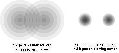
14 RESOLUTION IN THE LIGHT MICROSCOPE Resolution is the closest spacing of two points that are visible as distinct entities through the microscope In the light microscope, the quality of the objective lens plays a major role in determining the resolving power of the apparatus. However, the resolution in a light microscope is limited by a diffraction of light effect Diffraction: when light passes through an object the intensity is reduced depending upon the color absorbed. Thus the selective absorption of white light produces colored light Diffraction in a microscope occurs when a light wave passes very close to the edge of an object or through a tiny opening, such as a slit or aperture Short wavelengths are bent more than long wavelengths Dispersion 14


15 In the microscope, diffraction of light can occur at the specimen plane due to interaction of the light with small particles or features, and again at the margins of the objective front lens or at the edges of a circular aperture within or near the rear of the objective. It is this diffraction of light that makes it possible to observe magnified images of specimens in the microscope. However, it is also diffraction that limits the size of objects that can be resolved (limit the resolution) micro.magnet.fsu.edu/primer/lightandcolor/diffraction.htm 15

16 micro.magnet.fsu.edu/primer/lightandcolor/diffraction.htm 16
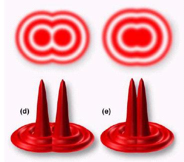
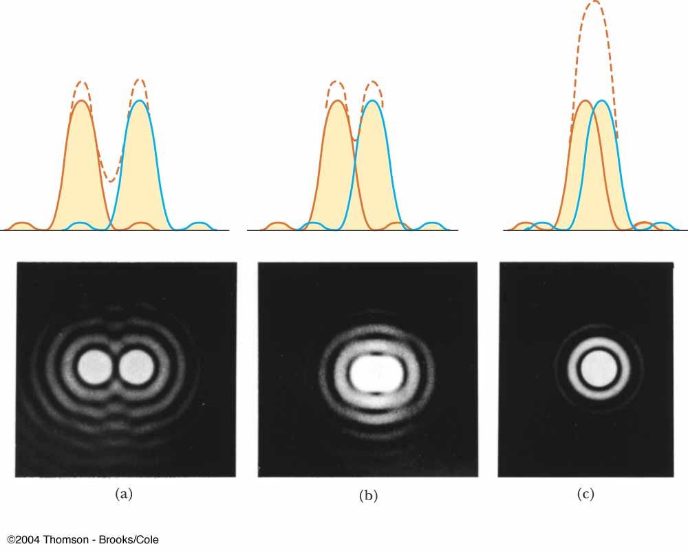
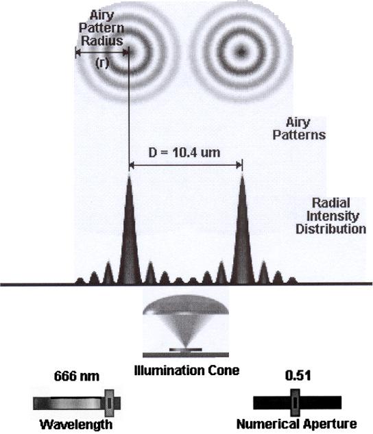
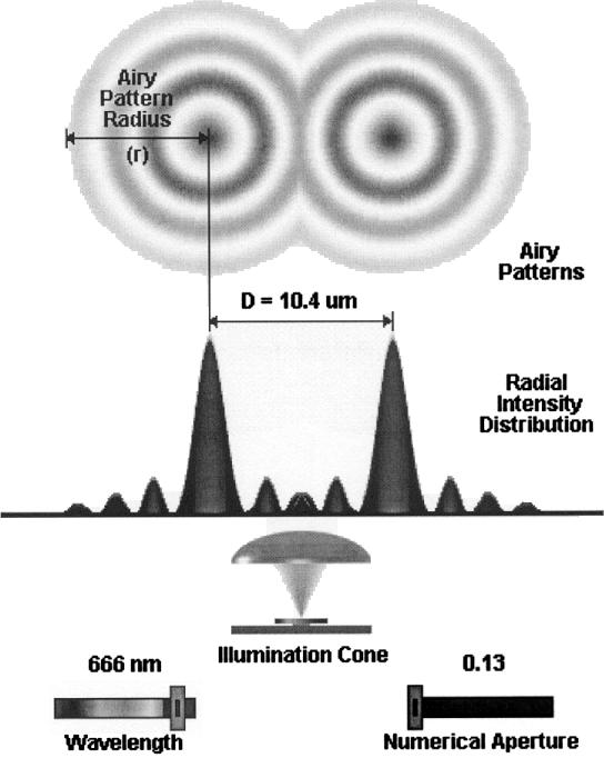
17 α r = d/2 Aperture Rayleigh s criterion: when the maximum of intensity of an Airy disc coincides with the first minimum of the second, then the two points can be distinguished RESOLUTION IN THE LIGHT MICROSCOPE From the diffraction theory, the resolution is given by Abbe s equation: d r = 2 = 0.61λ 0. 61λ = µ sin α NA λ is the wavelength of light, µ is the refractive index for the medium through which the light passes (air = 1, water = 1.33, oil = 1.4) The refractive index is = ratio of the speed of light in a vacuum to that in a second medium of greater density 17
18 µ sinα is called the numerical aperture (NA) In order to obtain higher resolution (smallest r), it is possible to decrease λ or increase µ or α. The higher the NA the greater the resolution The limits of the objective lens are that α cannot be greater than 90 o, and that the object space can only reach an NA = 1.4 Material Air Water Immersion oil Glass Zircon Diamond NA

19 N.A D - separation distance 19

20 DEPTH OF FIELD The depth of filed is defined as the distance from the nearest part of the specimen to the farthest part of the specimen that is in focus when the picture is being taken DEPTH OF FIELD The depth of field can be estimated from the Figure, which shows rays converging at the specimen. Simple geometry gives: 0.61λ h = µ sin α tan α h d A α Aperture Plane of optimum focus 20

 Light Microscope 200 nm (0.2 µm) SEM TEM 3 nm 0.2 nm This data is outdated!")
21 Light Microscope vs Electron Microscope As λ increases, r increases (low resolution) Best resolution is when λ is lowest Since electron microscopes use electron as illumination, λ is shorter, thus resolution is higher the source of OM SEM Depth of Field CONSIDERATIONS IN MICROSCOPY Magnification Resolution High magnification without high resolution is EMPTY EMPTY magnification RESOLVING LIMIT Eye 10 5 nm (0.1 mm) Light Microscope 200 nm (0.2 µm) SEM TEM 3 nm 0.2 nm This data is outdated!!! Check the latest machines 21

22 LENS ABERRATIONS Image quality, in all optical instruments, is limited by distortions which arise from optical defects called aberrations Lens aberrations include: Monochromatic (spherical) aberration Chromatic aberration Astigmatism Diffraction SPHERICAL ABERRATION Ideal lens These aberrations occur when light waves passing through the periphery of a lens are not brought into identical focus with those passing closer to the centre Electrons further from axis are focused closer than the electrons closer to axis 22

23 CHROMATIC ABERRATION Ideal lens These aberrations are the result of the fact that white light is composed of numerous wavelengths. When white light passes through a convex lens, the component wavelengths are refracted according to their frequency. ASTIGMATISM The off-axis image of a specimen point appears as a disc or blurred lines instead of a point Depending on the angle of the off- axis rays entering the lens, the line image may be oriented either tangentially or radially 23
Chapter 1. Basic Electron Optics (Lecture 2)
") Chapter 1. Basic Electron Optics (Lecture 2) Basic concepts of microscope (Cont ) Fundamental properties of electrons Electron Scattering Instrumentation Basic conceptions of microscope (Cont ) Ray diagram
Chapter 1. Basic Electron Optics (Lecture 2) Basic concepts of microscope (Cont ) Fundamental properties of electrons Electron Scattering Instrumentation Basic conceptions of microscope (Cont ) Ray diagram
VISUAL PHYSICS ONLINE DEPTH STUDY: ELECTRON MICROSCOPES
 VISUAL PHYSICS ONLINE DEPTH STUDY: ELECTRON MICROSCOPES Shortly after the experimental confirmation of the wave properties of the electron, it was suggested that the electron could be used to examine objects
Reflection! Reflection and Virtual Image!
 1/30/14 Reflection - wave hits non-absorptive surface surface of a smooth water pool - incident vs. reflected wave law of reflection - concept for all electromagnetic waves - wave theory: reflected back
Applied Optics. , Physics Department (Room #36-401) , ,
 , ,") Applied Optics Professor, Physics Department (Room #36-401) 2290-0923, 019-539-0923, shsong@hanyang.ac.kr Office Hours Mondays 15:00-16:30, Wednesdays 15:00-16:30 TA (Ph.D. student, Room #36-415) 2290-0921,
Applied Optics Professor, Physics Department (Room #36-401) 2290-0923, 019-539-0923, shsong@hanyang.ac.kr Office Hours Mondays 15:00-16:30, Wednesdays 15:00-16:30 TA (Ph.D. student, Room #36-415) 2290-0921,
Mirrors and Lenses. Images can be formed by reflection from mirrors. Images can be formed by refraction through lenses.
 Mirrors and Lenses Images can be formed by reflection from mirrors. Images can be formed by refraction through lenses. Notation for Mirrors and Lenses The object distance is the distance from the object
CCAM Microscope Objectives
 CCAM Microscope Objectives Things to consider when selecting an objective Magnification Numerical Aperture (NA) resolving power and light intensity of the objective Working Distance distance between the
The Nature of Light. Light and Energy
 The Nature of Light Light and Energy - dependent on energy from the sun, directly and indirectly - solar energy intimately associated with existence of life -light absorption: dissipate as heat emitted
Performance Factors. Technical Assistance. Fundamental Optics
 Performance Factors After paraxial formulas have been used to select values for component focal length(s) and diameter(s), the final step is to select actual lenses. As in any engineering problem, this
There is a range of distances over which objects will be in focus; this is called the depth of field of the lens. Objects closer or farther are
 Chapter 25 Optical Instruments Some Topics in Chapter 25 Cameras The Human Eye; Corrective Lenses Magnifying Glass Telescopes Compound Microscope Aberrations of Lenses and Mirrors Limits of Resolution
Exam 4. Name: Class: Date: Multiple Choice Identify the choice that best completes the statement or answers the question.
 Name: Class: Date: Exam 4 Multiple Choice Identify the choice that best completes the statement or answers the question. 1. Mirages are a result of which physical phenomena a. interference c. reflection
PHYSICS FOR THE IB DIPLOMA CAMBRIDGE UNIVERSITY PRESS
 Option C Imaging C Introduction to imaging Learning objectives In this section we discuss the formation of images by lenses and mirrors. We will learn how to construct images graphically as well as algebraically.
Basics of Light Microscopy and Metallography
 ENGR45: Introduction to Materials Spring 2012 Laboratory 8 Basics of Light Microscopy and Metallography In this exercise you will: gain familiarity with the proper use of a research-grade light microscope
Microscope anatomy, image formation and resolution
 Microscope anatomy, image formation and resolution Ian Dobbie Buy this book for your lab: D.B. Murphy, "Fundamentals of light microscopy and electronic imaging", ISBN 0-471-25391-X Visit these websites:
OPTICAL SYSTEMS OBJECTIVES
 101 L7 OPTICAL SYSTEMS OBJECTIVES Aims Your aim here should be to acquire a working knowledge of the basic components of optical systems and understand their purpose, function and limitations in terms
PHYSICS. Chapter 35 Lecture FOR SCIENTISTS AND ENGINEERS A STRATEGIC APPROACH 4/E RANDALL D. KNIGHT
 PHYSICS FOR SCIENTISTS AND ENGINEERS A STRATEGIC APPROACH 4/E Chapter 35 Lecture RANDALL D. KNIGHT Chapter 35 Optical Instruments IN THIS CHAPTER, you will learn about some common optical instruments and
Introduction to Light Microscopy. (Image: T. Wittman, Scripps)
") Introduction to Light Microscopy (Image: T. Wittman, Scripps) The Light Microscope Four centuries of history Vibrant current development One of the most widely used research tools A. Khodjakov et al. Major
Introduction to Light Microscopy (Image: T. Wittman, Scripps) The Light Microscope Four centuries of history Vibrant current development One of the most widely used research tools A. Khodjakov et al. Major
Chapters 1 & 2. Definitions and applications Conceptual basis of photogrammetric processing
 Chapters 1 & 2 Chapter 1: Photogrammetry Definitions and applications Conceptual basis of photogrammetric processing Transition from two-dimensional imagery to three-dimensional information Automation
Optical Components for Laser Applications. Günter Toesko - Laserseminar BLZ im Dezember
 Günter Toesko - Laserseminar BLZ im Dezember 2009 1 Aberrations An optical aberration is a distortion in the image formed by an optical system compared to the original. It can arise for a number of reasons
Name. Light Chapter Summary Cont d. Refraction
 Page 1 of 17 Physics Week 12(Sem. 2) Name Light Chapter Summary Cont d with a smaller index of refraction to a material with a larger index of refraction, the light refracts towards the normal line. Also,
COURSE NAME: PHOTOGRAPHY AND AUDIO VISUAL PRODUCTION (VOCATIONAL) FOR UNDER GRADUATE (FIRST YEAR)
 FOR UNDER GRADUATE (FIRST YEAR)") COURSE NAME: PHOTOGRAPHY AND AUDIO VISUAL PRODUCTION (VOCATIONAL) FOR UNDER GRADUATE (FIRST YEAR) PAPER TITLE: BASIC PHOTOGRAPHIC UNIT - 3 : SIMPLE LENS TOPIC: LENS PROPERTIES AND DEFECTS OBJECTIVES By
COURSE NAME: PHOTOGRAPHY AND AUDIO VISUAL PRODUCTION (VOCATIONAL) FOR UNDER GRADUATE (FIRST YEAR) PAPER TITLE: BASIC PHOTOGRAPHIC UNIT - 3 : SIMPLE LENS TOPIC: LENS PROPERTIES AND DEFECTS OBJECTIVES By
INTRODUCTION THIN LENSES. Introduction. given by the paraxial refraction equation derived last lecture: Thin lenses (19.1) = 1. Double-lens systems
 = 1. Double-lens systems") Chapter 9 OPTICAL INSTRUMENTS Introduction Thin lenses Double-lens systems Aberrations Camera Human eye Compound microscope Summary INTRODUCTION Knowledge of geometrical optics, diffraction and interference,
Chapter 9 OPTICAL INSTRUMENTS Introduction Thin lenses Double-lens systems Aberrations Camera Human eye Compound microscope Summary INTRODUCTION Knowledge of geometrical optics, diffraction and interference,
Applications of Optics
 Nicholas J. Giordano www.cengage.com/physics/giordano Chapter 26 Applications of Optics Marilyn Akins, PhD Broome Community College Applications of Optics Many devices are based on the principles of optics
IMAGE SENSOR SOLUTIONS. KAC-96-1/5" Lens Kit. KODAK KAC-96-1/5" Lens Kit. for use with the KODAK CMOS Image Sensors. November 2004 Revision 2
 KODAK for use with the KODAK CMOS Image Sensors November 2004 Revision 2 1.1 Introduction Choosing the right lens is a critical aspect of designing an imaging system. Typically the trade off between image
Chapter 25 Optical Instruments
 Chapter 25 Optical Instruments Units of Chapter 25 Cameras, Film, and Digital The Human Eye; Corrective Lenses Magnifying Glass Telescopes Compound Microscope Aberrations of Lenses and Mirrors Limits of
25 cm. 60 cm. 50 cm. 40 cm.
 Geometrical Optics 7. The image formed by a plane mirror is: (a) Real. (b) Virtual. (c) Erect and of equal size. (d) Laterally inverted. (e) B, c, and d. (f) A, b and c. 8. A real image is that: (a) Which
PHYS 202 OUTLINE FOR PART III LIGHT & OPTICS
 PHYS 202 OUTLINE FOR PART III LIGHT & OPTICS Electromagnetic Waves A. Electromagnetic waves S-23,24 1. speed of waves = 1/( o o ) ½ = 3 x 10 8 m/s = c 2. waves and frequency: the spectrum (a) radio red
Education in Microscopy and Digital Imaging
 Contact Us Carl Zeiss Education in Microscopy and Digital Imaging ZEISS Home Products Solutions Support Online Shop ZEISS International ZEISS Campus Home Interactive Tutorials Basic Microscopy Spectral
Waves & Oscillations
 Physics 42200 Waves & Oscillations Lecture 33 Geometric Optics Spring 2013 Semester Matthew Jones Aberrations We have continued to make approximations: Paraxial rays Spherical lenses Index of refraction
Average: Standard Deviation: Max: 99 Min: 40
 1 st Midterm Exam Average: 83.1 Standard Deviation: 12.0 Max: 99 Min: 40 Please contact me to fix an appointment, if you took less than 65. Chapter 33 Lenses and Op/cal Instruments Units of Chapter 33
Chapter 25. Optical Instruments
 Chapter 25 Optical Instruments Optical Instruments Analysis generally involves the laws of reflection and refraction Analysis uses the procedures of geometric optics To explain certain phenomena, the wave
Test Review # 8. Physics R: Form TR8.17A. Primary colors of light
 Physics R: Form TR8.17A TEST 8 REVIEW Name Date Period Test Review # 8 Light and Color. Color comes from light, an electromagnetic wave that travels in straight lines in all directions from a light source
CCAM s Selection of. Zeiss Microscope Objectives
 CCAM s Selection of Zeiss Microscope Objectives 1. Magnification Image scale 2. Resolution The minimum separation distance between two points that are clearly resolved. The resolution of an objective is
Waves & Oscillations
 Physics 42200 Waves & Oscillations Lecture 27 Geometric Optics Spring 205 Semester Matthew Jones Sign Conventions > + = Convex surface: is positive for objects on the incident-light side is positive for
OPTICS DIVISION B. School/#: Names:
 OPTICS DIVISION B School/#: Names: Directions: Fill in your response for each question in the space provided. All questions are worth two points. Multiple Choice (2 points each question) 1. Which of the
Study on Imaging Quality of Water Ball Lens
 2017 2nd International Conference on Mechatronics and Information Technology (ICMIT 2017) Study on Imaging Quality of Water Ball Lens Haiyan Yang1,a,*, Xiaopan Li 1,b, 1,c Hao Kong, 1,d Guangyang Xu and1,eyan
CHAPTER 18 REFRACTION & LENSES
 Physics Approximate Timeline Students are expected to keep up with class work when absent. CHAPTER 18 REFRACTION & LENSES Day Plans for the day Assignments for the day 1 18.1 Refraction of Light o Snell
Chapter Ray and Wave Optics
 109 Chapter Ray and Wave Optics 1. An astronomical telescope has a large aperture to [2002] reduce spherical aberration have high resolution increase span of observation have low dispersion. 2. If two
SUBJECT: PHYSICS. Use and Succeed.
 SUBJECT: PHYSICS I hope this collection of questions will help to test your preparation level and useful to recall the concepts in different areas of all the chapters. Use and Succeed. Navaneethakrishnan.V
LENSES. a. To study the nature of image formed by spherical lenses. b. To study the defects of spherical lenses.
 Purpose Theory LENSES a. To study the nature of image formed by spherical lenses. b. To study the defects of spherical lenses. formation by thin spherical lenses s are formed by lenses because of the refraction
PHYSICS OPTICS. Mr Rishi Gopie
 OPTICS Mr Rishi Gopie Ray Optics II Images formed by lens maybe real or virtual and may have different characteristics and locations that depend on: i) The type of lens involved, whether converging or
Chapter 2 - Geometric Optics
 David J. Starling Penn State Hazleton PHYS 214 The human eye is a visual system that collects light and forms an image on the retina. The human eye is a visual system that collects light and forms an image
Chapter 18 Optical Elements
 Chapter 18 Optical Elements GOALS When you have mastered the content of this chapter, you will be able to achieve the following goals: Definitions Define each of the following terms and use it in an operational
R.B.V.R.R. WOMEN S COLLEGE (AUTONOMOUS) Narayanaguda, Hyderabad.
 Narayanaguda, Hyderabad.") R.B.V.R.R. WOMEN S COLLEGE (AUTONOMOUS) Narayanaguda, Hyderabad. DEPARTMENT OF PHYSICS QUESTION BANK FOR SEMESTER III PAPER III OPTICS UNIT I: 1. MATRIX METHODS IN PARAXIAL OPTICS 2. ABERATIONS UNIT II
R.B.V.R.R. WOMEN S COLLEGE (AUTONOMOUS) Narayanaguda, Hyderabad. DEPARTMENT OF PHYSICS QUESTION BANK FOR SEMESTER III PAPER III OPTICS UNIT I: 1. MATRIX METHODS IN PARAXIAL OPTICS 2. ABERATIONS UNIT II
Microscopy: Fundamental Principles and Practical Approaches
 Microscopy: Fundamental Principles and Practical Approaches Simon Atkinson Online Resource: http://micro.magnet.fsu.edu/primer/index.html Book: Murphy, D.B. Fundamentals of Light Microscopy and Electronic
Practical Flatness Tech Note
 Practical Flatness Tech Note Understanding Laser Dichroic Performance BrightLine laser dichroic beamsplitters set a new standard for super-resolution microscopy with λ/10 flatness per inch, P-V. We ll
Notation for Mirrors and Lenses. Chapter 23. Types of Images for Mirrors and Lenses. More About Images
 Notation for Mirrors and Lenses Chapter 23 Mirrors and Lenses Sections: 4, 6 Problems:, 8, 2, 25, 27, 32 The object distance is the distance from the object to the mirror or lens Denoted by p The image
Observing Microorganisms through a Microscope LIGHT MICROSCOPY: This type of microscope uses visible light to observe specimens. Compound Light Micros
 PHARMACEUTICAL MICROBIOLOGY JIGAR SHAH INSTITUTE OF PHARMACY NIRMA UNIVERSITY Observing Microorganisms through a Microscope LIGHT MICROSCOPY: This type of microscope uses visible light to observe specimens.
ABC Math Student Copy. N. May ABC Math Student Copy. Physics Week 13(Sem. 2) Name. Light Chapter Summary Cont d 2
 Name. Light Chapter Summary Cont d 2") Page 1 of 12 Physics Week 13(Sem. 2) Name Light Chapter Summary Cont d 2 Lens Abberation Lenses can have two types of abberation, spherical and chromic. Abberation occurs when the rays forming an image
Page 1 of 12 Physics Week 13(Sem. 2) Name Light Chapter Summary Cont d 2 Lens Abberation Lenses can have two types of abberation, spherical and chromic. Abberation occurs when the rays forming an image
Image Formation. Light from distant things. Geometrical optics. Pinhole camera. Chapter 36
 Light from distant things Chapter 36 We learn about a distant thing from the light it generates or redirects. The lenses in our eyes create images of objects our brains can process. This chapter concerns
Exam 3--PHYS 2021M-Spring 2009
 Name: Class: Date: Exam 3--PHYS 2021M-Spring 2009 Multiple Choice Identify the choice that best completes the statement or answers the question Each question is worth 2 points 1 Images made by mirrors
Laboratory experiment aberrations
 Laboratory experiment aberrations Obligatory laboratory experiment on course in Optical design, SK2330/SK3330, KTH. Date Name Pass Objective This laboratory experiment is intended to demonstrate the most
Physics 11. Unit 8 Geometric Optics Part 2
 Physics 11 Unit 8 Geometric Optics Part 2 (c) Refraction (i) Introduction: Snell s law Like water waves, when light is traveling from one medium to another, not only does its wavelength, and in turn the
Chapter 23. Mirrors and Lenses
 Chapter 23 Mirrors and Lenses Mirrors and Lenses The development of mirrors and lenses aided the progress of science. It led to the microscopes and telescopes. Allowed the study of objects from microbes
Biology 29 Cell Structure and Function Spring, 2009 Springer LABORATORY 1: THE LIGHT MICROSCOPE
 Biology 29 Cell Structure and Function Spring, 2009 Springer LABORATORY 1: THE LIGHT MICROSCOPE Prior to lab: 1) Read these instructions (p 1-6) 2) Go through the online tutorial, the microscopy pre-lab
Physics 1C. Lecture 25B
 Physics 1C Lecture 25B "More than 50 years ago, Austrian researcher Ivo Kohler gave people goggles thats severely distorted their vision: The lenses turned the world upside down. After several weeks, subjects
Reflection and Refraction of Light
 Reflection and Refraction of Light Physics 102 28 March 2002 Lecture 6 28 Mar 2002 Physics 102 Lecture 6 1 Light waves and light rays Last time we showed: Time varying B fields E fields B fields to create
Reflectors vs. Refractors
 1 Telescope Types - Telescopes collect and concentrate light (which can then be magnified, dispersed as a spectrum, etc). - In the end it is the collecting area that counts. - There are two primary telescope
Biomedical Imaging 生物醫學影像學
 Biomedical Imaging 生物醫學影像學 楊自森助理教授 牙體技術學系 2013/02/24 tsyang@tmu.edu.tw 1 Course Outline 1. Course Introduction 2. Basic Optics and Light Microscopes 3. Fluorescence/Confocal/TIRF Microscopes 4. FRET Techniques
Lecture Outline Chapter 27. Physics, 4 th Edition James S. Walker. Copyright 2010 Pearson Education, Inc.
 Lecture Outline Chapter 27 Physics, 4 th Edition James S. Walker Chapter 27 Optical Instruments Units of Chapter 27 The Human Eye and the Camera Lenses in Combination and Corrective Optics The Magnifying
Very short introduction to light microscopy and digital imaging
 Very short introduction to light microscopy and digital imaging Hernan G. Garcia August 1, 2005 1 Light Microscopy Basics In this section we will briefly describe the basic principles of operation and
Test procedures Page: 1 of 5
 Test procedures Page: 1 of 5 1 Scope This part of document establishes uniform requirements for measuring the numerical aperture of optical fibre, thereby assisting in the inspection of fibres and cables
Introduction to Electron Microscopy
 Introduction to Electron Microscopy Prof. David Muller, dm24@cornell.edu Rm 274 Clark Hall, 255-4065 Ernst Ruska and Max Knoll built the first electron microscope in 1931 (Nobel Prize to Ruska in 1986)
WHS-CH-23 Light: Geometric Optics Show all your work, equations used, and box in your answers!
 WHS-CH-23 Light: Geometric Optics Show all your work, equations used, and box in your answers! Willebrord Snell (1591-1626) Snell developed methods for measuring the Earth. He proposed the method of triangulation
INDEX OF REFRACTION index of refraction n = c/v material index of refraction n
 INDEX OF REFRACTION The index of refraction (n) of a material is the ratio of the speed of light in vacuuo (c) to the speed of light in the material (v). n = c/v Indices of refraction for any materials
2. The reflected-light microscopy, description and function of a reflected-light microscope
 2. The reflected-light microscopy, description and function of a reflected-light microscope 2.1. The reflected-light microscopy 2.2. The appearance of polished sections under the reflected-light microscope
GIST OF THE UNIT BASED ON DIFFERENT CONCEPTS IN THE UNIT (BRIEFLY AS POINT WISE). RAY OPTICS
. RAY OPTICS") 209 GIST OF THE UNIT BASED ON DIFFERENT CONCEPTS IN THE UNIT (BRIEFLY AS POINT WISE). RAY OPTICS Reflection of light: - The bouncing of light back into the same medium from a surface is called reflection
209 GIST OF THE UNIT BASED ON DIFFERENT CONCEPTS IN THE UNIT (BRIEFLY AS POINT WISE). RAY OPTICS Reflection of light: - The bouncing of light back into the same medium from a surface is called reflection
OPTICAL PRINCIPLES OF MICROSCOPY. Interuniversity Course 28 December 2003 Aryeh M. Weiss Bar Ilan University
 OPTICAL PRINCIPLES OF MICROSCOPY Interuniversity Course 28 December 2003 Aryeh M. Weiss Bar Ilan University FOREWORD This slide set was originally presented at the ISM Workshop on Theoretical and Experimental
EE119 Introduction to Optical Engineering Spring 2003 Final Exam. Name:
 EE119 Introduction to Optical Engineering Spring 2003 Final Exam Name: SID: CLOSED BOOK. THREE 8 1/2 X 11 SHEETS OF NOTES, AND SCIENTIFIC POCKET CALCULATOR PERMITTED. TIME ALLOTTED: 180 MINUTES Fundamental
Ch 24. Geometric Optics
 text concept Ch 24. Geometric Optics Fig. 24 3 A point source of light P and its image P, in a plane mirror. Angle of incidence =angle of reflection. text. Fig. 24 4 The blue dashed line through object
Tissue Preparation ORGANISM IMAGE TISSUE PREPARATION. 1) Fixation: halts cell metabolism, preserves cell/tissue structure
 Fixation: halts cell metabolism, preserves cell/tissue structure") Lab starts this week! ANNOUNCEMENTS - Tuesday or Wednesday 1:25 ISB 264 - Read Lab 1: Microscopy and Imaging (see Web Page) - Getting started on Lab Group project - Organ for investigation - Lab project
Lab starts this week! ANNOUNCEMENTS - Tuesday or Wednesday 1:25 ISB 264 - Read Lab 1: Microscopy and Imaging (see Web Page) - Getting started on Lab Group project - Organ for investigation - Lab project
Chapter 23. Mirrors and Lenses
 Chapter 23 Mirrors and Lenses Notation for Mirrors and Lenses The object distance is the distance from the object to the mirror or lens Denoted by p The image distance is the distance from the image to
Phy Ph s y 102 Lecture Lectur 21 Optical instruments 1
 Phys 102 Lecture 21 Optical instruments 1 Today we will... Learn how combinations of lenses form images Thin lens equation & magnification Learn about the compound microscope Eyepiece & objective Total
Lecture 21. Physics 1202: Lecture 21 Today s Agenda
 Physics 1202: Lecture 21 Today s Agenda Announcements: Team problems today Team 14: Gregory Desautels, Benjamin Hallisey, Kyle Mcginnis Team 15: Austin Dion, Nicholas Gandza, Paul Macgillis-Falcon Homework
Converging and Diverging Surfaces. Lenses. Converging Surface
 Lenses Sandy Skoglund 2 Converging and Diverging s AIR Converging If the surface is convex, it is a converging surface in the sense that the parallel rays bend toward each other after passing through the
Phys 102 Lecture 21 Optical instruments
 Phys 102 Lecture 21 Optical instruments 1 Today we will... Learn how combinations of lenses form images Thin lens equation & magnification Learn about the compound microscope Eyepiece & objective Total
AP Physics Problems -- Waves and Light
 AP Physics Problems -- Waves and Light 1. 1974-3 (Geometric Optics) An object 1.0 cm high is placed 4 cm away from a converging lens having a focal length of 3 cm. a. Sketch a principal ray diagram for
Physics II. Chapter 23. Spring 2018
 Physics II Chapter 23 Spring 2018 IMPORTANT: Except for multiple-choice questions, you will receive no credit if you show only an answer, even if the answer is correct. Always show in the space on your
Chapter 23. Light Geometric Optics
 Chapter 23. Light Geometric Optics There are 3 basic ways to gather light and focus it to make an image. Pinhole - Simple geometry Mirror - Reflection Lens - Refraction Pinhole Camera Image Formation (the
Heisenberg) relation applied to space and transverse wavevector
 relation applied to space and transverse wavevector") 2. Optical Microscopy 2.1 Principles A microscope is in principle nothing else than a simple lens system for magnifying small objects. The first lens, called the objective, has a short focal length (a
2. Optical Microscopy 2.1 Principles A microscope is in principle nothing else than a simple lens system for magnifying small objects. The first lens, called the objective, has a short focal length (a
Chapter 26. The Refraction of Light: Lenses and Optical Instruments
 Chapter 26 The Refraction of Light: Lenses and Optical Instruments 26.1 The Index of Refraction Light travels through a vacuum at a speed c=3. 00 10 8 m/ s Light travels through materials at a speed less
Test Review # 9. Physics R: Form TR9.15A. Primary colors of light
 Physics R: Form TR9.15A TEST 9 REVIEW Name Date Period Test Review # 9 Light and Color. Color comes from light, an electromagnetic wave that travels in straight lines in all directions from a light source
Phys214 Fall 2004 Midterm Form A
 1. A clear sheet of polaroid is placed on top of a similar sheet so that their polarizing axes make an angle of 30 with each other. The ratio of the intensity of emerging light to incident unpolarized
Chapter 34 Geometric Optics (also known as Ray Optics) by C.-R. Hu
 by C.-R. Hu") Chapter 34 Geometric Optics (also known as Ray Optics) by C.-R. Hu 1. Principles of image formation by mirrors (1a) When all length scales of objects, gaps, and holes are much larger than the wavelength
Chapter 34 Geometric Optics (also known as Ray Optics) by C.-R. Hu 1. Principles of image formation by mirrors (1a) When all length scales of objects, gaps, and holes are much larger than the wavelength
EE-527: MicroFabrication
 EE-57: MicroFabrication Exposure and Imaging Photons white light Hg arc lamp filtered Hg arc lamp excimer laser x-rays from synchrotron Electrons Ions Exposure Sources focused electron beam direct write
Chapter 29/30. Wave Fronts and Rays. Refraction of Sound. Dispersion in a Prism. Index of Refraction. Refraction and Lenses
 Chapter 29/30 Refraction and Lenses Refraction Refraction the bending of waves as they pass from one medium into another. Caused by a change in the average speed of light. Analogy A car that drives off
MICROSCOPE LAB. Resolving Power How well specimen detail is preserved during the magnifying process.
 AP BIOLOGY Cells ACTIVITY #2 MICROSCOPE LAB OBJECTIVES 1. Demonstrate proper care and use of a compound microscope. 2. Identify the parts of the microscope and describe the function of each part. 3. Compare
Lecture PowerPoint. Chapter 25 Physics: Principles with Applications, 6 th edition Giancoli
 Lecture PowerPoint Chapter 25 Physics: Principles with Applications, 6 th edition Giancoli 2005 Pearson Prentice Hall This work is protected by United States copyright laws and is provided solely for the
Transmission electron Microscopy
 Transmission electron Microscopy Image formation of a concave lens in geometrical optics Some basic features of the transmission electron microscope (TEM) can be understood from by analogy with the operation
Chapter 3 Op,cal Instrumenta,on
 Imaging by an Op,cal System Change in curvature of wavefronts by a thin lens Chapter 3 Op,cal Instrumenta,on 3-1 Stops, Pupils, and Windows 3-4 The Camera 3-5 Simple Magnifiers and Eyepieces 1. Magnifiers
Microscope. Dr. Leena Barhate Department of Microbiology M.J.College, Jalgaon
 Microscope Dr. Leena Barhate Department of Microbiology M.J.College, Jalgaon Acknowledgement http://www.cerebromente.org.br/n17/histor y/neurons1_i.htm Google Images http://science.howstuffworks.com/lightmicroscope1.htm
Determination of Focal Length of A Converging Lens and Mirror
 Physics 41 Determination of Focal Length of A Converging Lens and Mirror Objective: Apply the thin-lens equation and the mirror equation to determine the focal length of a converging (biconvex) lens and
microscopy A great online resource Molecular Expressions, a Microscope Primer Partha Roy
 Fundamentals of optical microscopy A great online resource Molecular Expressions, a Microscope Primer http://micro.magnet.fsu.edu/primer/index.html Partha Roy 1 Why microscopy Topics Functions of a microscope
Chapter 3 Op+cal Instrumenta+on
 Chapter 3 Op+cal Instrumenta+on 3-1 Stops, Pupils, and Windows 3-4 The Camera 3-5 Simple Magnifiers and Eyepieces 3-6 Microscopes 3-7 Telescopes Today (2011-09-22) 1. Magnifiers 2. Camera 3. Resolution
Converging Lenses. Parallel rays are brought to a focus by a converging lens (one that is thicker in the center than it is at the edge).
.") Chapter 30: Lenses Types of Lenses Piece of glass or transparent material that bends parallel rays of light so they cross and form an image Two types: Converging Diverging Converging Lenses Parallel rays
Chapter 30: Lenses Types of Lenses Piece of glass or transparent material that bends parallel rays of light so they cross and form an image Two types: Converging Diverging Converging Lenses Parallel rays
Fabrication of Probes for High Resolution Optical Microscopy
 Fabrication of Probes for High Resolution Optical Microscopy Physics 564 Applied Optics Professor Andrès La Rosa David Logan May 27, 2010 Abstract Near Field Scanning Optical Microscopy (NSOM) is a technique
Lecture 8. Lecture 8. r 1
 Lecture 8 Achromat Design Design starts with desired Next choose your glass materials, i.e. Find P D P D, then get f D P D K K Choose radii (still some freedom left in choice of radii for minimization
Criteria for Optical Systems: Optical Path Difference How do we determine the quality of a lens system? Several criteria used in optical design
 Criteria for Optical Systems: Optical Path Difference How do we determine the quality of a lens system? Several criteria used in optical design Computer Aided Design Several CAD tools use Ray Tracing (see
Big League Cryogenics and Vacuum The LHC at CERN
 Big League Cryogenics and Vacuum The LHC at CERN A typical astronomical instrument must maintain about one cubic meter at a pressure of
Properties of optical instruments. Projection optical systems
 Properties of optical instruments Projection optical systems Instruments : optical systems designed for a specific function Projection systems: : real image (object real or at infinity) Examples: videoprojector,,
Laboratory 7: Properties of Lenses and Mirrors
 Laboratory 7: Properties of Lenses and Mirrors Converging and Diverging Lens Focal Lengths: A converging lens is thicker at the center than at the periphery and light from an object at infinity passes