Chapter 3 Op+cal Instrumenta+on
|
|
|
- Magdalen Price
- 5 years ago
- Views:
Transcription
1 Chapter 3 Op+cal Instrumenta+on 3-1 Stops, Pupils, and Windows 3-4 The Camera 3-5 Simple Magnifiers and Eyepieces 3-6 Microscopes 3-7 Telescopes Today ( ) 1. Magnifiers 2. Camera 3. Resolution limit 4. Microscopes 5. Telescopes 3-2 A brief look at aberrations 3-3 Prisms next week ( Sep 27 )
2 Imaging by an Op+cal System Change in curvature of wavefronts by a thin lens
3 Simple Magnifiers M α M α 0 = h / s h / 25 = 25 s M = 25 f M = 25 f [ cm] image at infinity (s = f ) +1[ cm] image at normal near point (s' = 25cm)
4 The Camera Pinhole Camera Simple Camera
 A zoom lens changes the effective focal length by varying the")
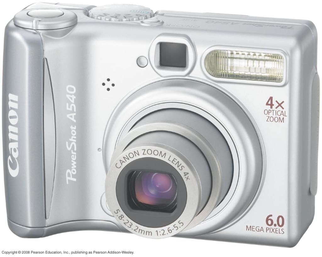
5 The Camera A camera takes a picture by using a lens to form a real, inverted image on a light-sensitive detector in a light-tight box. We can model a combination lens as a single lens with an effective focal length (usually called simply the focal length ) A zoom lens changes the effective focal length by varying the spacing between the converging lens and the diverging lens.


6 The Camera: Components
7 QUESTION: Example Focusing a camera
8 Example Focusing a camera
9 Zoom Lenses When cameras focus on objects that are more that 10 focal lengths away (roughly s > 20 cm for a typical digital camera), the object is essentially at infinity and s' f. The lateral magnification of the image is The magnification is much less than 1, because s >> f, so the image on the detector is much smaller than the object itself. More important, the size of the image is directly proportional to the focal length of the lens.
10 Controlling the Exposure The amount of light passing through the lens is controlled by an adjustable aperture, also called an iris because it functions much like the iris of your eye. The aperture sets the effective diameter D of the lens. By long tradition, the light-gathering ability of a lens is specified by its f-number, defined as
11 f- number and irradiance/intensity [W/m 2 ] The light intensity on the detector is related to the lens s f-number by 2 1.4
12 Depth of Field & Example 3-3 (p. 73) ( s o f ) f 2 depth of field = 2Ads o f 4 A 2 d 2 2 s o
13 A lens both focuses and diffracts the light

14 The Resolu9on of Op9cal Instruments The minimum spot size to which a lens can focus light of wavelength λ is where D is the diameter of the circular aperture of the lens, and f is the focal length. In order to resolve two points, their angular separation must be greater than θ min, where is called the angular resolution of the lens.
15 Important Concepts
16 Thin Lens Combina+on è Sequen+al Imaging Reading Assignments 1. Example 2-3 (page 38) 2. Java Applets h\p://silver.neep.wisc.edu/~shock/tools/ray.html (See also Lab #1 Appendix)
17 Important Concepts
18 The Microscope
19 The Microscope A specimen to be observed is placed on the stage of a microscope, directly beneath the objective, a converging lens with a relatively short focal length. The objective creates a magnified real image that is further enlarged by the eyepiece. The lateral magnification of the objective is Together, the objective and eyepiece produce a total angular magnification


20 The Microscope: Objec+ve and Numerical Aperture (NA) NA = n sinα Oil- immersion microscope
21 QUESTION: Example: Viewing blood cells
22 Example: Viewing blood cells
23 Telescope M = α ' α = f o f e L = f o + f e D ex = D obj M the diameter of the exit pupil
24 The Telescope A simple telescope contains a large-diameter objective lens which collects parallel rays from a distant object and forms a real, inverted image at distance s' = f obj. The focal length of a telescope objective is very nearly the length of the telescope tube. The eyepiece functions as a simple magnifier. The viewer observes an inverted image. The angular magnification of a telescope is
25 Stops, Pupils, and Windows Summary of Terms Brightness Aperture stop AS: The real element in an optical system that limits the size of the cone of rays accepted by the system from an axial object point. Entrance pupil E n P: The image of the aperture stop formed by the optical elements (if any) that precede it. Exit pupil E x P: The image of the aperture stop formed by the optical elements (if any) that follow it. Field of view Field stop ES: The real element that limits the angular field of view formed by an optical system. Entrance window E n W: The image of the field stop formed by the optical elements (if any) that precede it. Exit window E x W: The image of the field stop formed by the optical elements (if any) that follow it. Chief Ray The chief, or principal, ray is a ray from an object point that passes through the axial point, in the plane of the entrance pupil.
26 Limita+on of light rays in a two- posi+ve- lens system
27 A biologist rotates the turret of a microscope to replace a 20 objec+ve with a 10 objec+ve. To keep the same overall magnifica+on, the focal length of the eyepiece must be A. Halved. B. Doubled. C. Kept the same. D. The magnification cannot be kept the same if the objective is changed.
28 Four diffrac+on- limited lenses focus plane waves of light with the same wavelength l. Rank order, from largest to smallest, the spot sizes w 1 to w 4. A. w 2 = w 3 > w 4 > w 1 B. w 1 = w 2 > w 3 > w 4 C. w 4 > w 3 > w 1 = w 2 D. w 1 > w 4 > w 2 = w 3 E. w 2 > w 1 = w 3 > w 4
29 Example 3-1
30 Example 3-1: Solu+on
31 A biologist rotates the turret of a microscope to replace a 20 objec+ve with a 10 objec+ve. To keep the same overall magnifica+on, the focal length of the eyepiece must be A. Halved. B. Doubled. C. Kept the same. D. The magnification cannot be kept the same if the objective is changed.
32 Four diffrac+on- limited lenses focus plane waves of light with the same wavelength l. Rank order, from largest to smallest, the spot sizes w 1 to w 4. A. w 2 = w 3 > w 4 > w 1 B. w 1 = w 2 > w 3 > w 4 C. w 4 > w 3 > w 1 = w 2 D. w 1 > w 4 > w 2 = w 3 E. w 2 > w 1 = w 3 > w 4
Chapter 3 Op,cal Instrumenta,on
 Imaging by an Op,cal System Change in curvature of wavefronts by a thin lens Chapter 3 Op,cal Instrumenta,on 3-1 Stops, Pupils, and Windows 3-4 The Camera 3-5 Simple Magnifiers and Eyepieces 1. Magnifiers
PHYSICS. Chapter 35 Lecture FOR SCIENTISTS AND ENGINEERS A STRATEGIC APPROACH 4/E RANDALL D. KNIGHT
 PHYSICS FOR SCIENTISTS AND ENGINEERS A STRATEGIC APPROACH 4/E Chapter 35 Lecture RANDALL D. KNIGHT Chapter 35 Optical Instruments IN THIS CHAPTER, you will learn about some common optical instruments and
PHY385H1F Introductory Optics. Practicals Session 7 Studying for Test 2
 PHY385H1F Introductory Optics Practicals Session 7 Studying for Test 2 Entrance Pupil & Exit Pupil A Cooke-triplet consists of three thin lenses in succession, and is often used in cameras. It was patented
There is a range of distances over which objects will be in focus; this is called the depth of field of the lens. Objects closer or farther are
 Chapter 25 Optical Instruments Some Topics in Chapter 25 Cameras The Human Eye; Corrective Lenses Magnifying Glass Telescopes Compound Microscope Aberrations of Lenses and Mirrors Limits of Resolution
Types of lenses. Shown below are various types of lenses, both converging and diverging.
 Types of lenses Shown below are various types of lenses, both converging and diverging. Any lens that is thicker at its center than at its edges is a converging lens with positive f; and any lens that
Option G 2: Lenses. The diagram below shows the image of a square grid as produced by a lens that does not cause spherical aberration.
 Name: Date: Option G 2: Lenses 1. This question is about spherical aberration. The diagram below shows the image of a square grid as produced by a lens that does not cause spherical aberration. In the
Properties of optical instruments. Visual optical systems part 2: focal visual instruments (microscope type)
") Properties of optical instruments Visual optical systems part 2: focal visual instruments (microscope type) Examples of focal visual instruments magnifying glass Eyepieces Measuring microscopes from the
Properties of optical instruments Visual optical systems part 2: focal visual instruments (microscope type) Examples of focal visual instruments magnifying glass Eyepieces Measuring microscopes from the
OPTICAL SYSTEMS OBJECTIVES
 101 L7 OPTICAL SYSTEMS OBJECTIVES Aims Your aim here should be to acquire a working knowledge of the basic components of optical systems and understand their purpose, function and limitations in terms
Chapter 25 Optical Instruments
 Chapter 25 Optical Instruments Units of Chapter 25 Cameras, Film, and Digital The Human Eye; Corrective Lenses Magnifying Glass Telescopes Compound Microscope Aberrations of Lenses and Mirrors Limits of
Chapter 25. Optical Instruments
 Chapter 25 Optical Instruments Optical Instruments Analysis generally involves the laws of reflection and refraction Analysis uses the procedures of geometric optics To explain certain phenomena, the wave
Average: Standard Deviation: Max: 99 Min: 40
 1 st Midterm Exam Average: 83.1 Standard Deviation: 12.0 Max: 99 Min: 40 Please contact me to fix an appointment, if you took less than 65. Chapter 33 Lenses and Op/cal Instruments Units of Chapter 33
Physics 1C. Lecture 25B
 Physics 1C Lecture 25B "More than 50 years ago, Austrian researcher Ivo Kohler gave people goggles thats severely distorted their vision: The lenses turned the world upside down. After several weeks, subjects
Opti 415/515. Introduction to Optical Systems. Copyright 2009, William P. Kuhn
 Opti 415/515 Introduction to Optical Systems 1 Optical Systems Manipulate light to form an image on a detector. Point source microscope Hubble telescope (NASA) 2 Fundamental System Requirements Application
Properties of optical instruments. Projection optical systems
 Properties of optical instruments Projection optical systems Instruments : optical systems designed for a specific function Projection systems: : real image (object real or at infinity) Examples: videoprojector,,
General Physics II. Optical Instruments
 General Physics II Optical Instruments 1 The Thin-Lens Equation 2 The Thin-Lens Equation Using geometry, one can show that 1 1 1 s+ =. s' f The magnification of the lens is defined by For a thin lens,
ECEN 4606, UNDERGRADUATE OPTICS LAB
 ECEN 4606, UNDERGRADUATE OPTICS LAB Lab 2: Imaging 1 the Telescope Original Version: Prof. McLeod SUMMARY: In this lab you will become familiar with the use of one or more lenses to create images of distant
TOPICS Recap of PHYS110-1 lecture Physical Optics - 4 lectures EM spectrum and colour Light sources Interference and diffraction Polarization
 TOPICS Recap of PHYS110-1 lecture Physical Optics - 4 lectures EM spectrum and colour Light sources Interference and diffraction Polarization Lens Aberrations - 3 lectures Spherical aberrations Coma, astigmatism,
VISUAL PHYSICS ONLINE DEPTH STUDY: ELECTRON MICROSCOPES
 VISUAL PHYSICS ONLINE DEPTH STUDY: ELECTRON MICROSCOPES Shortly after the experimental confirmation of the wave properties of the electron, it was suggested that the electron could be used to examine objects
Lecture 4: Geometrical Optics 2. Optical Systems. Images and Pupils. Rays. Wavefronts. Aberrations. Outline
 Lecture 4: Geometrical Optics 2 Outline 1 Optical Systems 2 Images and Pupils 3 Rays 4 Wavefronts 5 Aberrations Christoph U. Keller, Leiden University, keller@strw.leidenuniv.nl Lecture 4: Geometrical
PHY385H1F Introductory Optics Term Test 2 November 6, 2012 Duration: 50 minutes. NAME: Student Number:.
 PHY385H1F Introductory Optics Term Test 2 November 6, 2012 Duration: 50 minutes NAME: Student Number:. Aids allowed: A pocket calculator with no communication ability. One 8.5x11 aid sheet, written on
INTRODUCTION THIN LENSES. Introduction. given by the paraxial refraction equation derived last lecture: Thin lenses (19.1) = 1. Double-lens systems
 = 1. Double-lens systems") Chapter 9 OPTICAL INSTRUMENTS Introduction Thin lenses Double-lens systems Aberrations Camera Human eye Compound microscope Summary INTRODUCTION Knowledge of geometrical optics, diffraction and interference,
Chapter 9 OPTICAL INSTRUMENTS Introduction Thin lenses Double-lens systems Aberrations Camera Human eye Compound microscope Summary INTRODUCTION Knowledge of geometrical optics, diffraction and interference,
Chapter 36. Image Formation
 Chapter 36 Image Formation Image of Formation Images can result when light rays encounter flat or curved surfaces between two media. Images can be formed either by reflection or refraction due to these
13. Optical Instruments*
 13. Optical Instruments* Objective: Here what you have been learning about thin lenses is applied to make a telescope. In the process you encounter general optical instrument design concepts. The learning
Applications of Optics
 Nicholas J. Giordano www.cengage.com/physics/giordano Chapter 26 Applications of Optics Marilyn Akins, PhD Broome Community College Applications of Optics Many devices are based on the principles of optics
Physics 6C. Cameras and the Human Eye. Prepared by Vince Zaccone For Campus Learning Assistance Services at UCSB
 Physics 6C Cameras and the Human Eye CAMERAS A typical camera uses a converging lens to focus a real (inverted) image onto photographic film (or in a digital camera the image is on a CCD chip). Light goes
ECEG105/ECEU646 Optics for Engineers Course Notes Part 4: Apertures, Aberrations Prof. Charles A. DiMarzio Northeastern University Fall 2008
 ECEG105/ECEU646 Optics for Engineers Course Notes Part 4: Apertures, Aberrations Prof. Charles A. DiMarzio Northeastern University Fall 2008 July 2003+ Chuck DiMarzio, Northeastern University 11270-04-1
Lecture Outline Chapter 27. Physics, 4 th Edition James S. Walker. Copyright 2010 Pearson Education, Inc.
 Lecture Outline Chapter 27 Physics, 4 th Edition James S. Walker Chapter 27 Optical Instruments Units of Chapter 27 The Human Eye and the Camera Lenses in Combination and Corrective Optics The Magnifying
PHYS 202 OUTLINE FOR PART III LIGHT & OPTICS
 PHYS 202 OUTLINE FOR PART III LIGHT & OPTICS Electromagnetic Waves A. Electromagnetic waves S-23,24 1. speed of waves = 1/( o o ) ½ = 3 x 10 8 m/s = c 2. waves and frequency: the spectrum (a) radio red
Chapter Ray and Wave Optics
 109 Chapter Ray and Wave Optics 1. An astronomical telescope has a large aperture to [2002] reduce spherical aberration have high resolution increase span of observation have low dispersion. 2. If two
Chapter 36. Image Formation
 Chapter 36 Image Formation Notation for Mirrors and Lenses The object distance is the distance from the object to the mirror or lens Denoted by p The image distance is the distance from the image to the
Lecture 8. Lecture 8. r 1
 Lecture 8 Achromat Design Design starts with desired Next choose your glass materials, i.e. Find P D P D, then get f D P D K K Choose radii (still some freedom left in choice of radii for minimization
Converging and Diverging Surfaces. Lenses. Converging Surface
 Lenses Sandy Skoglund 2 Converging and Diverging s AIR Converging If the surface is convex, it is a converging surface in the sense that the parallel rays bend toward each other after passing through the
Activity 6.1 Image Formation from Spherical Mirrors
 PHY385H1F Introductory Optics Practicals Day 6 Telescopes and Microscopes October 31, 2011 Group Number (number on Intro Optics Kit):. Facilitator Name:. Record-Keeper Name: Time-keeper:. Computer/Wiki-master:..
Applied Optics. , Physics Department (Room #36-401) , ,
 , ,") Applied Optics Professor, Physics Department (Room #36-401) 2290-0923, 019-539-0923, shsong@hanyang.ac.kr Office Hours Mondays 15:00-16:30, Wednesdays 15:00-16:30 TA (Ph.D. student, Room #36-415) 2290-0921,
Applied Optics Professor, Physics Department (Room #36-401) 2290-0923, 019-539-0923, shsong@hanyang.ac.kr Office Hours Mondays 15:00-16:30, Wednesdays 15:00-16:30 TA (Ph.D. student, Room #36-415) 2290-0921,
Phy Ph s y 102 Lecture Lectur 21 Optical instruments 1
 Phys 102 Lecture 21 Optical instruments 1 Today we will... Learn how combinations of lenses form images Thin lens equation & magnification Learn about the compound microscope Eyepiece & objective Total
Chapter 34: Geometrical Optics (Part 2)
") Chapter 34: Geometrical Optics (Part 2) Brief review Optical instruments Camera Human eye Magnifying glass Telescope Microscope Optical Aberrations Phys Phys 2435: 22: Chap. 34, 31, Pg 1 The Lens Equation
Chapter 34: Geometrical Optics (Part 2) Brief review Optical instruments Camera Human eye Magnifying glass Telescope Microscope Optical Aberrations Phys Phys 2435: 22: Chap. 34, 31, Pg 1 The Lens Equation
PHYSICS FOR THE IB DIPLOMA CAMBRIDGE UNIVERSITY PRESS
 Option C Imaging C Introduction to imaging Learning objectives In this section we discuss the formation of images by lenses and mirrors. We will learn how to construct images graphically as well as algebraically.
Chapter 3 Optical Instrumentation
 Chapter 3 Optical Instrumentation Lecture Notes for Modern Optics based on Pedrotti & Pedrotti & Pedrotti Instructor: Nayer Eradat Spring 29 3/11/29 Eradat, SJSU, Optical Instrumentation 1 Stops, pupils,
Phys 102 Lecture 21 Optical instruments
 Phys 102 Lecture 21 Optical instruments 1 Today we will... Learn how combinations of lenses form images Thin lens equation & magnification Learn about the compound microscope Eyepiece & objective Total
Imaging Instruments (part I)
") Imaging Instruments (part I) Principal Planes and Focal Lengths (Effective, Back, Front) Multi-element systems Pupils & Windows; Apertures & Stops the Numerical Aperture and f/# Single-Lens Camera Human
Imaging Instruments (part I) Principal Planes and Focal Lengths (Effective, Back, Front) Multi-element systems Pupils & Windows; Apertures & Stops the Numerical Aperture and f/# Single-Lens Camera Human
Chapter 34. Images. Copyright 2014 John Wiley & Sons, Inc. All rights reserved.
 Chapter 34 Images Copyright 34-1 Images and Plane Mirrors Learning Objectives 34.01 Distinguish virtual images from real images. 34.02 Explain the common roadway mirage. 34.03 Sketch a ray diagram for
Geometrical Optics Optical systems
 Phys 322 Lecture 16 Chapter 5 Geometrical Optics Optical systems Magnifying glass Purpose: enlarge a nearby object by increasing its image size on retina Requirements: Image should not be inverted Image
SUBJECT: PHYSICS. Use and Succeed.
 SUBJECT: PHYSICS I hope this collection of questions will help to test your preparation level and useful to recall the concepts in different areas of all the chapters. Use and Succeed. Navaneethakrishnan.V
THIN LENSES: APPLICATIONS
 THIN LENSES: APPLICATIONS OBJECTIVE: To see how thin lenses are used in three important cases: the eye, the telescope and the microscope. Part 1: The Eye and Visual Acuity THEORY: We can think of light
Lecture 2: Geometrical Optics. Geometrical Approximation. Lenses. Mirrors. Optical Systems. Images and Pupils. Aberrations.
 Lecture 2: Geometrical Optics Outline 1 Geometrical Approximation 2 Lenses 3 Mirrors 4 Optical Systems 5 Images and Pupils 6 Aberrations Christoph U. Keller, Leiden Observatory, keller@strw.leidenuniv.nl
Properties of optical instruments
 Properties of optical instruments Visual optical systems part 1: afocal systems (telescope type) A basic optical description of the eye Power: 60 diopters (at rest) Equivalent to a single spherical surface,
25 cm. 60 cm. 50 cm. 40 cm.
 Geometrical Optics 7. The image formed by a plane mirror is: (a) Real. (b) Virtual. (c) Erect and of equal size. (d) Laterally inverted. (e) B, c, and d. (f) A, b and c. 8. A real image is that: (a) Which
University of Rochester Department of Physics and Astronomy Physics123, Spring Homework 5 - Solutions
 Problem 5. University of Rochester Department of Physics and Astronomy Physics23, Spring 202 Homework 5 - Solutions An optometrist finds that a farsighted person has a near point at 25 cm. a) If the eye
Chapter 3 Optical Systems
 Chapter 3 Optical Systems The Human Eye [Reading Assignment, Hecht 5.7.1-5.7.3; see also Smith Chapter 5] retina aqueous vitreous fovea-macula cornea lens blind spot optic nerve iris cornea f b aqueous
PHYSICS 289 Experiment 8 Fall Geometric Optics II Thin Lenses
 PHYSICS 289 Experiment 8 Fall 2005 Geometric Optics II Thin Lenses Please look at the chapter on lenses in your text before this lab experiment. Please submit a short lab report which includes answers
PHY 431 Homework Set #5 Due Nov. 20 at the start of class
 PHY 431 Homework Set #5 Due Nov. 0 at the start of class 1) Newton s rings (10%) The radius of curvature of the convex surface of a plano-convex lens is 30 cm. The lens is placed with its convex side down
30 Lenses. Lenses change the paths of light.
 Lenses change the paths of light. A light ray bends as it enters glass and bends again as it leaves. Light passing through glass of a certain shape can form an image that appears larger, smaller, closer,
Lecture 2: Geometrical Optics. Geometrical Approximation. Lenses. Mirrors. Optical Systems. Images and Pupils. Aberrations.
 Lecture 2: Geometrical Optics Outline 1 Geometrical Approximation 2 Lenses 3 Mirrors 4 Optical Systems 5 Images and Pupils 6 Aberrations Christoph U. Keller, Leiden Observatory, keller@strw.leidenuniv.nl
Chapter 18 Optical Elements
 Chapter 18 Optical Elements GOALS When you have mastered the content of this chapter, you will be able to achieve the following goals: Definitions Define each of the following terms and use it in an operational
Optical Systems. The normal eye
 Optical Systems The normal eye The ciliary muscles can adjust the shape of the lens of the human eye. As the eye attempts to see objects at different distances, the muscles will adjust the focal length
Phys 531 Lecture 9 30 September 2004 Ray Optics II. + 1 s i. = 1 f
 Phys 531 Lecture 9 30 September 2004 Ray Optics II Last time, developed idea of ray optics approximation to wave theory Introduced paraxial approximation: rays with θ 1 Will continue to use Started disussing
microscopy A great online resource Molecular Expressions, a Microscope Primer Partha Roy
 Fundamentals of optical microscopy A great online resource Molecular Expressions, a Microscope Primer http://micro.magnet.fsu.edu/primer/index.html Partha Roy 1 Why microscopy Topics Functions of a microscope
Physics 1202: Lecture 19 Today s Agenda
 Physics 1202: Lecture 19 Today s Agenda Announcements: Team problems today Team 12: Kervell Baird, Matthew George, Derek Schultz Team 13: Paxton Stowik, Stacey Ann Burke Team 14: Gregory Desautels, Benjamin
Physics Chapter Review Chapter 25- The Eye and Optical Instruments Ethan Blitstein
 Physics Chapter Review Chapter 25- The Eye and Optical Instruments Ethan Blitstein The Human Eye As light enters through the human eye it first passes through the cornea (a thin transparent membrane of
Introduction to Light Microscopy. (Image: T. Wittman, Scripps)
") Introduction to Light Microscopy (Image: T. Wittman, Scripps) The Light Microscope Four centuries of history Vibrant current development One of the most widely used research tools A. Khodjakov et al. Major
Introduction to Light Microscopy (Image: T. Wittman, Scripps) The Light Microscope Four centuries of history Vibrant current development One of the most widely used research tools A. Khodjakov et al. Major
Microscope anatomy, image formation and resolution
 Microscope anatomy, image formation and resolution Ian Dobbie Buy this book for your lab: D.B. Murphy, "Fundamentals of light microscopy and electronic imaging", ISBN 0-471-25391-X Visit these websites:
PHY 1160C Homework Chapter 26: Optical Instruments Ch 26: 2, 3, 5, 9, 13, 15, 20, 25, 27
 PHY 60C Homework Chapter 26: Optical Instruments Ch 26: 2, 3, 5, 9, 3, 5, 20, 25, 27 26.2 A pin-hole camera is used to take a photograph of a student who is.8 m tall. The student stands 2.7 m in front
2.71 Optics Fall 05 QUIZ 1 Wednesday, Oct. 12, 2005
 2.71 Quiz 1 MASSACHUSETTS INSTITUTE OF TECHNOLOGY 2.71 Optics Fall 05 QUIZ 1 Wednesday, Oct. 12, 2005 1. (60%) The optical instrument shown below is a telephoto lens. It consists of a combination of two
O5: Lenses and the refractor telescope
 O5. 1 O5: Lenses and the refractor telescope Introduction In this experiment, you will study converging lenses and the lens equation. You will make several measurements of the focal length of lenses and
sclera pupil What happens to light that enters the eye?
 Human Vision Textbook pages 202 215 Before You Read Some people can see things clearly from a great distance. Other people can see things clearly only when they are nearby. Why might this be? Write your
[ Summary. 3i = 1* 6i = 4J;
 the projections at angle 2. We calculate the difference between the measured projections at angle 2 (6 and 14) and the projections based on the previous esti mate (top row: 2>\ + 6\ = 10; same for bottom
Exam 4. Name: Class: Date: Multiple Choice Identify the choice that best completes the statement or answers the question.
 Name: Class: Date: Exam 4 Multiple Choice Identify the choice that best completes the statement or answers the question. 1. Mirages are a result of which physical phenomena a. interference c. reflection
Chapter 24 Geometrical Optics. Copyright 2010 Pearson Education, Inc.
 Chapter 24 Geometrical Optics Lenses convex (converging) concave (diverging) Mirrors Ray Tracing for Mirrors We use three principal rays in finding the image produced by a curved mirror. The parallel ray
BASICS IN BIOIMAGING AND OPTICS PLATFORM EPFL SV PTBIOP LIGHT MICROSCOPY
 BASICS IN LIGHT MICROSCOPY OVERVIEW 1. Motivation 2. Basic in optics 3. How microscope works 4. Illumination and resolution 5. Microscope optics 6. Contrasting methods -2- MOTIVATION Why do we need microscopy?
Physics 11. Unit 8 Geometric Optics Part 2
 Physics 11 Unit 8 Geometric Optics Part 2 (c) Refraction (i) Introduction: Snell s law Like water waves, when light is traveling from one medium to another, not only does its wavelength, and in turn the
Chapter 34: Geometric Optics
 Chapter 34: Geometric Optics It is all about images How we can make different kinds of images using optical devices Optical device example: mirror, a piece of glass, telescope, microscope, kaleidoscope,
Imaging Introduction. September 24, 2010
 Imaging Introduction September 24, 2010 What is a microscope? Merriam-Webster: an optical instrument consisting of a lens or combination of lenses for making enlarged images of minute objects; especially:
Reading: Lenses and Mirrors; Applications Key concepts: Focal points and lengths; real images; virtual images; magnification; angular magnification.
 Reading: Lenses and Mirrors; Applications Key concepts: Focal points and lengths; real images; virtual images; magnification; angular magnification. 1.! Questions about objects and images. Can a virtual
Readings: Hecht, Chapter 24
 5. GEOMETRIC OPTICS Readings: Hecht, Chapter 24 Introduction In this lab you will measure the index of refraction of glass using Snell s Law, study the application of the laws of geometric optics to systems
Lens Design I. Lecture 5: Advanced handling I Herbert Gross. Summer term
 Lens Design I Lecture 5: Advanced handling I 2018-05-17 Herbert Gross Summer term 2018 www.iap.uni-jena.de 2 Preliminary Schedule - Lens Design I 2018 1 12.04. Basics 2 19.04. Properties of optical systems
Chapter 34 Geometric Optics (also known as Ray Optics) by C.-R. Hu
 by C.-R. Hu") Chapter 34 Geometric Optics (also known as Ray Optics) by C.-R. Hu 1. Principles of image formation by mirrors (1a) When all length scales of objects, gaps, and holes are much larger than the wavelength
Chapter 34 Geometric Optics (also known as Ray Optics) by C.-R. Hu 1. Principles of image formation by mirrors (1a) When all length scales of objects, gaps, and holes are much larger than the wavelength
Lecture PowerPoint. Chapter 25 Physics: Principles with Applications, 6 th edition Giancoli
 Lecture PowerPoint Chapter 25 Physics: Principles with Applications, 6 th edition Giancoli 2005 Pearson Prentice Hall This work is protected by United States copyright laws and is provided solely for the
Geometric!Op9cs! Reflec9on! Refrac9on!`!Snell s!law! Mirrors!and!Lenses! Other!topics! Thin!Lens!Equa9on! Magnifica9on! Lensmaker s!formula!
 Geometric!Op9cs! Reflec9on! Refrac9on!`!Snell s!law! Mirrors!and!Lenses! Thin!Lens!Equa9on! Magnifica9on! Lensmaker s!formula! Other!topics! Telescopes! Apertures! Reflec9on! Angle!of!incidence!equals!angle!of!reflec9on!
REFLECTION THROUGH LENS
 REFLECTION THROUGH LENS A lens is a piece of transparent optical material with one or two curved surfaces to refract light rays. It may converge or diverge light rays to form an image. Lenses are mostly
CCAM Microscope Objectives
 CCAM Microscope Objectives Things to consider when selecting an objective Magnification Numerical Aperture (NA) resolving power and light intensity of the objective Working Distance distance between the
Light microscopy. Part II
 Light microscopy Part II What is numerical aperature (NA)? Usually, higher magnifica>on objec>ves have greater NAs Sample specifica>ons objective magnification NA working distance (mm) Achromat 10x 0.25
Department of Physics & Astronomy Undergraduate Labs. Thin Lenses
 Thin Lenses Reflection and Refraction When light passes from one medium to another, part of the light is reflected and the rest is transmitted. Light rays that are transmitted undergo refraction (bending)
Magnification, stops, mirrors More geometric optics
 Magnification, stops, mirrors More geometric optics D. Craig 2005-02-25 Transverse magnification Refer to figure 5.22. By convention, distances above the optical axis are taken positive, those below, negative.
Cardinal Points of an Optical System--and Other Basic Facts
 Cardinal Points of an Optical System--and Other Basic Facts The fundamental feature of any optical system is the aperture stop. Thus, the most fundamental optical system is the pinhole camera. The image
Laboratory experiment aberrations
 Laboratory experiment aberrations Obligatory laboratory experiment on course in Optical design, SK2330/SK3330, KTH. Date Name Pass Objective This laboratory experiment is intended to demonstrate the most
Section A Conceptual and application type questions. 1 Which is more observable diffraction of light or sound? Justify. (1)
") INDIAN SCHOOL MUSCAT Department of Physics Class : XII Physics Worksheet - 6 (2017-2018) Chapter 9 and 10 : Ray Optics and wave Optics Section A Conceptual and application type questions 1 Which is more
INDIAN SCHOOL MUSCAT Department of Physics Class : XII Physics Worksheet - 6 (2017-2018) Chapter 9 and 10 : Ray Optics and wave Optics Section A Conceptual and application type questions 1 Which is more
Image Formation. Light from distant things. Geometrical optics. Pinhole camera. Chapter 36
 Light from distant things Chapter 36 We learn about a distant thing from the light it generates or redirects. The lenses in our eyes create images of objects our brains can process. This chapter concerns
Test Review # 8. Physics R: Form TR8.17A. Primary colors of light
 Physics R: Form TR8.17A TEST 8 REVIEW Name Date Period Test Review # 8 Light and Color. Color comes from light, an electromagnetic wave that travels in straight lines in all directions from a light source
Astronomical Cameras
 Astronomical Cameras I. The Pinhole Camera Pinhole Camera (or Camera Obscura) Whenever light passes through a small hole or aperture it creates an image opposite the hole This is an effect wherever apertures
Optical Components for Laser Applications. Günter Toesko - Laserseminar BLZ im Dezember
 Günter Toesko - Laserseminar BLZ im Dezember 2009 1 Aberrations An optical aberration is a distortion in the image formed by an optical system compared to the original. It can arise for a number of reasons
Chapter 2 - Geometric Optics
 David J. Starling Penn State Hazleton PHYS 214 The human eye is a visual system that collects light and forms an image on the retina. The human eye is a visual system that collects light and forms an image
Education in Microscopy and Digital Imaging
 Contact Us Carl Zeiss Education in Microscopy and Digital Imaging ZEISS Home Products Solutions Support Online Shop ZEISS International ZEISS Campus Home Interactive Tutorials Basic Microscopy Spectral
Physics 431 Final Exam Examples (3:00-5:00 pm 12/16/2009) TIME ALLOTTED: 120 MINUTES Name: Signature:
 TIME ALLOTTED: 120 MINUTES Name: Signature:") Physics 431 Final Exam Examples (3:00-5:00 pm 12/16/2009) TIME ALLOTTED: 120 MINUTES Name: PID: Signature: CLOSED BOOK. TWO 8 1/2 X 11 SHEET OF NOTES (double sided is allowed), AND SCIENTIFIC POCKET CALCULATOR
Physics 431 Final Exam Examples (3:00-5:00 pm 12/16/2009) TIME ALLOTTED: 120 MINUTES Name: PID: Signature: CLOSED BOOK. TWO 8 1/2 X 11 SHEET OF NOTES (double sided is allowed), AND SCIENTIFIC POCKET CALCULATOR
GIST OF THE UNIT BASED ON DIFFERENT CONCEPTS IN THE UNIT (BRIEFLY AS POINT WISE). RAY OPTICS
. RAY OPTICS") 209 GIST OF THE UNIT BASED ON DIFFERENT CONCEPTS IN THE UNIT (BRIEFLY AS POINT WISE). RAY OPTICS Reflection of light: - The bouncing of light back into the same medium from a surface is called reflection
209 GIST OF THE UNIT BASED ON DIFFERENT CONCEPTS IN THE UNIT (BRIEFLY AS POINT WISE). RAY OPTICS Reflection of light: - The bouncing of light back into the same medium from a surface is called reflection
Chapter 29/30. Wave Fronts and Rays. Refraction of Sound. Dispersion in a Prism. Index of Refraction. Refraction and Lenses
 Chapter 29/30 Refraction and Lenses Refraction Refraction the bending of waves as they pass from one medium into another. Caused by a change in the average speed of light. Analogy A car that drives off
NANO 703-Notes. Chapter 9-The Instrument
 1 Chapter 9-The Instrument Illumination (condenser) system Before (above) the sample, the purpose of electron lenses is to form the beam/probe that will illuminate the sample. Our electron source is macroscopic
Lab 11: Lenses and Ray Tracing
 Name: Lab 11: Lenses and Ray Tracing Group Members: Date: TA s Name: Materials: Ray box, two different converging lenses, one diverging lens, screen, lighted object, three stands, meter stick, two letter
GEOMETRICAL OPTICS AND OPTICAL DESIGN
 GEOMETRICAL OPTICS AND OPTICAL DESIGN Pantazis Mouroulis Associate Professor Center for Imaging Science Rochester Institute of Technology John Macdonald Senior Lecturer Physics Department University of
Physics 141 Lecture 28
 Physics 141 Lecture 28 Today s Concept: A) Op3cal Devices Electricity & Magne/sm Lecture 28, Slide 1 Executive Summary Mirrors & Lenses: S > 2f real inverted smaller f > 0 2f > S > f real inverted bigger
L. R. & S. M. VISSANJI ACADEMY SECONDARY SECTION PHYSICS-GRADE: VIII OPTICAL INSTRUMENTS
 L. R. & S. M. VISSANJI ACADEMY SECONDARY SECTION - 2016-17 PHYSICS-GRADE: VIII OPTICAL INSTRUMENTS SIMPLE MICROSCOPE A simple microscope consists of a single convex lens of a short focal length. The object