Applied Optics. , Physics Department (Room #36-401) , ,
|
|
|
- Arabella Harris
- 5 years ago
- Views:
Transcription
1 Applied Optics Professor, Physics Department (Room #36-401) , , Office Hours Mondays 15:00-16:30, Wednesdays 15:00-16:30 TA (Ph.D. student, Room #36-415) , Grades Midterm Exam 30%, Final Exam 30%, Homework 20%, Attend & Quiz 10% Textbook Introduction to Optics (Wiley, New York, 1986) Homepage

2 Optics Reference :
3 Light is a Ray (Geometrical Optics) A. General Properties of Light Rays B. Reflection and Refraction C. Prisms and Dispersion D. Images Formed by Light Rays Reflected and Refracted at Planar Interfaces E. Images Formed by Light Rays Reflected and Refracted at Curved Interfaces F. Thin Lenses G. Ray Tracing Through More Complex Optical Systems H. Ray Aberrations I. Optical Instruments Viewed by Eye J. Ray Optics Description of a Waveguide Trapping Light by TIR Light is a Wave (Physical Optics) A. Wave Basics B. Interference of Two Waves C. Interference in Thin Films D. Interferometers E. Holography F. Diffraction of Light G. Polarization of Light Course outline Light is a Photon (Quantum Optics) A. Where Does Light Come From? Sources of Light B. The Laser C. How Do You Know Light is There? Detecting Light
4 Geometrical Optics - light is a ray Geometrical optics Ignore wave nature of light. No diffraction. Light travels in straight lines. Rays. Rays subjected to reflection and refraction. Obey laws of reflection and refraction. Light Ray Line in direction of flow of radiant energy
5 Geometrical Optics - light is a ray Light Ray : the path along which light energy is transmitted from one point to another in an optical system. Speed of Light : Speed of light (in vacuum): a fundamental (or a defined ) constant of nature given by c = 299,792,458 meters / second = 186,300 miles / second. Index of Refraction
6 Reflection
7 Plane of incidence Incident & reflected rays + normal in same plane normal Incident ray θ i θ r reflected ray
8 Refraction

9 Refraction Snell s Law
10 Refraction Snell s Law n i sin θ = i n t sinθ t ni nt < 0????


11 Negative Refraction : n < 0 RHM N > 1 LHM N = -1
12 Prism and Dispersion
13 Images Formed by Rays Reflected at Planar Interfaces
14 Images Formed by Rays Refracted at Planar Interfaces
15 Prisms to Alter the Orientation of Images
16 Images Formed by Rays Reflected at Curved Interfaces
17 Images Formed by Rays Refracted at Curved Interfaces
18 Image Formation by a Thin Lens
19 Spherical Lens Lens usually have both sides spherical Or, one side flat and the other spherical. Easier to make. lens R 2 R 1
20 Lensmaker s Formula = ( n 1) s s' R R 1 2 n s S
21 Sign Convention Rays travel from left to right. Object distance, S positive if one left of lens negative if on right of lens Image distance, S positive if one right of lens negative if on left of lens R 1 & R 2 positive if centre on right of lens negative if centre on left of lens
22 Plano-concave R 1 > 0 R 2 < 0 R 1 = R 2 < 0 R 1 > 0 R 2 > 0 Bi-convex Plano-convex Meniscus convex R 1 < 0 R 2 > 0 R 1 = R 2 > 0 R 1 > 0 R 2 > 0
23 Focal Points for Converging Lens Parallel rays made to cross at focal point by lens. Focal point f
24 Focal Length Distance from lens to focal point. Parallel rays means S =, S = f so = + = ( n 1) s s' f R R 1 2 or = ( n 1) f R1 R2 Giving the thin lens equation = s s' f
25 Focal Points for Converging Lens Rays from focal point made parallel by lens. Focal point f
26 Focal Points for Diverging Lens Point from which parallel rays appear to diverge after passing through the lens. Focal point f
27 Focal Points for Diverging Lens Point to which converging rays are directed when lens makes rays parallel. Focal point f
28 Positive and Negative Lenses For a converging lens So, f is positive. Converging lenses called positive lens For a diverging lens So, f is negative. 1 1 > R 0 1 R < R 0 1 R 2 Diverging lenses called negative lens
29 Real and Virtual Images Real image One beyond lens (to right) Rays converge onto it. Can be projected onto a screen S positive Virtual image One behind lens (to left) Rays diverge from it. Cannot be projected onto a screen S negative.
30 Real Image Produced by convex (positive) lens Object beyond focus u v Focus Real Image Object Focus f f
31 Virtual Image Can be by concave (negative) lens Object beyond focus Image reduced u -v Focus Object Virtual Image Focus
32 Real and Virtual Objects Real object One in front of lens (to left) Rays diverge from it. S positive Virtual object One beyond lens (to right) Rays converge towards it. S negative.
33 Numerical Aperture (N.A.) Describes the quality of a lens. Depends on size of the lens or aperture of lens working distance refractive index Given by equation N.A. = nsin α n is refractive index between object and lens α is the half acceptance angle of lens.
34 Some examples of N.A In all cases, lens is in air (n = 1) 5mm 20 mm 5mm 10mm α 2.5 mm α 10mm α 2.5 tan α= = sin α = sin ( tan ( 0.25 )) = sin = N. A. = tan α= = sin α = sin ( tan ( 1.0) ) = sin = N. A. = tan α= = sin α= sin ( tan ( 1.0) ) = sin = N.A. = 0.707
35 Power of Lens Power of lens Inverse of the focal length in meters Measured in dioptres, D. P = 1 f I.e. lens focal length 50 cm has power of 1 =
36 Magnification Magnification, M Ratio of image height to object height. object y o y So M = u Positive when image erect i Negative when image inverted y o v y i image
37 Magnification object B y o S C D A S y i image Two similar triangles ABC and DEC So M y = i = S' y S o E
38 Focal point Focal point
39 Combining Lenses More than one lens Thin lens equation applied in turn. Image of one lens is object of next. object intermediate image Final image
40 Ray Tracing Through Complex Optical Systems

41 Losses and Aberrations of Rays
42 Aberrations Imperfections reduce theoretical resolution of lens. As N.A. increases, aberrations get worse. Increases with increasing lens power Many different types of aberrations. Chromatic Spherical Coma Curvature of field etc.
43 Chromatic Aberration Different colours focused at different points. Combination of lenses decreases problem. Combination called an Achromat. hite urce Blue Green Red
44 Achromatic Doublet Positive lens from crown glass Low dispersion Negative lens form flint glass High dispersion
45 Achromatic Doublet First lens stronger than second Pair are positive First lens focuses blue more strongly Second lens corrects for this Greater dispersion Only correct for two colours Usually red and blue If two close surfaces made same curvature Lenses can be cemented together.
46 Spherical aberration Edges of a lens refract light more then the centre. Most of the rays focus together to form a disc Called the circle of least confusion. Circle of least confusion Focus of outer rays Focus of inner rays
47 Coma Edge of lens different focal length to centre Rays at angle focused at different points Produces comet like image
48 Curvature of field Lens focuses on surface of a sphere. As object moves off the optical axis focal distance to the lens is farther. Gives either pin cushion or barrel distortion. minimised by the use of compensating lenses. Curved focal field


49 Distortion Off-axis magnification different from central magnification Pincushion or barrel distortion Object Barrel Pin cushion
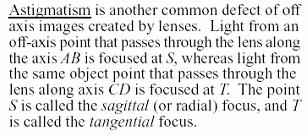
50 Astigmatism
51 Stops A stop is an aperture in a system Often to reduce aberrations Aberrations greater at edge of lens Exit pupil Stop Entrance pupil Image f 1 Object lens 1 f 2 lens 2 f 1 f2
52 Entrance and Exit Pupil Entrance pupil Virtual image of stop by lens 1 Exit pupil Virtual image of stop by lens 2 Size of pupil depends on viewing direction Gives diameter of aperture of light for system
53 Resolution Ability to discern fine details. Expressed as a linear dimension. For typical electron microscope is ~ 0.2nm. Objects separated by >0.2nm will be resolved as being separate. Lord Rayleigh in 1896 first described resolution as a function of the Airy disc. Airy discs of two point light sources
54 Rayleigh Criterion Rayleigh: Limit of resolution Two light sources must be separated by at least the diameter of first dark band. Light distribution of a cross section of respective airy disc.
55 Abbé derived an expression for resolution Comes from size of the lens that captures light. Resolving power = 0.61 λ N.A. The resolution will be expressed in the same units as the wavelength of the light.
56 Depth of Field Area in front of and behind the specimen that will be in acceptable focus. Determined by numerical aperture. epth of field In focus Depth of field In focus
57 Depth of Field & Focus Depth of field concerns focus plane of specimen. D fi λ ( N.A. ) 2 Range of acceptable focus for the image is called depth of focus. = depth of focus depth of focus
58 Depth of Focus Nearly same as depth of field Determined by magnification as well. Higher magnification depth of field becomes shorter, higher magnification increase depth of focus for image. Depth of focus given by R.P. is the resolving power. D fo = M 2 R.P. N.A.
59 Size of image on retina depends on distance from eye Closest distance called near point. Varies with age and eye defects. Varies with age as lens becomes less flexible. 10 years old ~ 7cm 25 years old ~ 12 cm 45 years old ~ 28 cm 50 years old ~ 40 cm 60 years old ~ 100 cm 70 years old ~ 400 cm Normally given as 25 cm
60 Optical Instruments Viewed by Eye : Microscope L=16cm in general, 20X means that f = 16cm/20 = 8 mm
61 Optical Instruments : Telescope α ' M = = α telescope f f objective eyepiece
62 Waveguides Trapping Light by TIR
Average: Standard Deviation: Max: 99 Min: 40
 1 st Midterm Exam Average: 83.1 Standard Deviation: 12.0 Max: 99 Min: 40 Please contact me to fix an appointment, if you took less than 65. Chapter 33 Lenses and Op/cal Instruments Units of Chapter 33
CHAPTER 18 REFRACTION & LENSES
 Physics Approximate Timeline Students are expected to keep up with class work when absent. CHAPTER 18 REFRACTION & LENSES Day Plans for the day Assignments for the day 1 18.1 Refraction of Light o Snell
Mirrors and Lenses. Images can be formed by reflection from mirrors. Images can be formed by refraction through lenses.
 Mirrors and Lenses Images can be formed by reflection from mirrors. Images can be formed by refraction through lenses. Notation for Mirrors and Lenses The object distance is the distance from the object
OPTICAL SYSTEMS OBJECTIVES
 101 L7 OPTICAL SYSTEMS OBJECTIVES Aims Your aim here should be to acquire a working knowledge of the basic components of optical systems and understand their purpose, function and limitations in terms
Astronomy 80 B: Light. Lecture 9: curved mirrors, lenses, aberrations 29 April 2003 Jerry Nelson
 Astronomy 80 B: Light Lecture 9: curved mirrors, lenses, aberrations 29 April 2003 Jerry Nelson Sensitive Countries LLNL field trip 2003 April 29 80B-Light 2 Topics for Today Optical illusion Reflections
Chapter Ray and Wave Optics
 109 Chapter Ray and Wave Optics 1. An astronomical telescope has a large aperture to [2002] reduce spherical aberration have high resolution increase span of observation have low dispersion. 2. If two
PHYSICS FOR THE IB DIPLOMA CAMBRIDGE UNIVERSITY PRESS
 Option C Imaging C Introduction to imaging Learning objectives In this section we discuss the formation of images by lenses and mirrors. We will learn how to construct images graphically as well as algebraically.
Name. Light Chapter Summary Cont d. Refraction
 Page 1 of 17 Physics Week 12(Sem. 2) Name Light Chapter Summary Cont d with a smaller index of refraction to a material with a larger index of refraction, the light refracts towards the normal line. Also,
Converging and Diverging Surfaces. Lenses. Converging Surface
 Lenses Sandy Skoglund 2 Converging and Diverging s AIR Converging If the surface is convex, it is a converging surface in the sense that the parallel rays bend toward each other after passing through the
University of Rochester Department of Physics and Astronomy Physics123, Spring Homework 5 - Solutions
 Problem 5. University of Rochester Department of Physics and Astronomy Physics23, Spring 202 Homework 5 - Solutions An optometrist finds that a farsighted person has a near point at 25 cm. a) If the eye
EE119 Introduction to Optical Engineering Spring 2002 Final Exam. Name:
 EE119 Introduction to Optical Engineering Spring 2002 Final Exam Name: SID: CLOSED BOOK. FOUR 8 1/2 X 11 SHEETS OF NOTES, AND SCIENTIFIC POCKET CALCULATOR PERMITTED. TIME ALLOTTED: 180 MINUTES Fundamental
25 cm. 60 cm. 50 cm. 40 cm.
 Geometrical Optics 7. The image formed by a plane mirror is: (a) Real. (b) Virtual. (c) Erect and of equal size. (d) Laterally inverted. (e) B, c, and d. (f) A, b and c. 8. A real image is that: (a) Which
Optical Systems: Pinhole Camera Pinhole camera: simple hole in a box: Called Camera Obscura Aristotle discussed, Al-Hazen analyzed in Book of Optics
 Optical Systems: Pinhole Camera Pinhole camera: simple hole in a box: Called Camera Obscura Aristotle discussed, Al-Hazen analyzed in Book of Optics 1011CE Restricts rays: acts as a single lens: inverts
Ch 24. Geometric Optics
 text concept Ch 24. Geometric Optics Fig. 24 3 A point source of light P and its image P, in a plane mirror. Angle of incidence =angle of reflection. text. Fig. 24 4 The blue dashed line through object
Lecture 2: Geometrical Optics. Geometrical Approximation. Lenses. Mirrors. Optical Systems. Images and Pupils. Aberrations.
 Lecture 2: Geometrical Optics Outline 1 Geometrical Approximation 2 Lenses 3 Mirrors 4 Optical Systems 5 Images and Pupils 6 Aberrations Christoph U. Keller, Leiden Observatory, keller@strw.leidenuniv.nl
INDEX OF REFRACTION index of refraction n = c/v material index of refraction n
 INDEX OF REFRACTION The index of refraction (n) of a material is the ratio of the speed of light in vacuuo (c) to the speed of light in the material (v). n = c/v Indices of refraction for any materials
Physics II. Chapter 23. Spring 2018
 Physics II Chapter 23 Spring 2018 IMPORTANT: Except for multiple-choice questions, you will receive no credit if you show only an answer, even if the answer is correct. Always show in the space on your
Geometric Optics. Ray Model. assume light travels in straight line uses rays to understand and predict reflection & refraction
 Geometric Optics Ray Model assume light travels in straight line uses rays to understand and predict reflection & refraction General Physics 2 Geometric Optics 1 Reflection Law of reflection the angle
Condition Mirror Refractive Lens Concave Focal Length Positive Focal Length Negative. Image distance positive
 Comparison between mirror lenses and refractive lenses Condition Mirror Refractive Lens Concave Focal Length Positive Focal Length Negative Convex Focal Length Negative Focal Length Positive Image location
Chapter 34 Geometric Optics (also known as Ray Optics) by C.-R. Hu
 by C.-R. Hu") Chapter 34 Geometric Optics (also known as Ray Optics) by C.-R. Hu 1. Principles of image formation by mirrors (1a) When all length scales of objects, gaps, and holes are much larger than the wavelength
Chapter 34 Geometric Optics (also known as Ray Optics) by C.-R. Hu 1. Principles of image formation by mirrors (1a) When all length scales of objects, gaps, and holes are much larger than the wavelength
Image Formation. Light from distant things. Geometrical optics. Pinhole camera. Chapter 36
 Light from distant things Chapter 36 We learn about a distant thing from the light it generates or redirects. The lenses in our eyes create images of objects our brains can process. This chapter concerns
R.B.V.R.R. WOMEN S COLLEGE (AUTONOMOUS) Narayanaguda, Hyderabad.
 Narayanaguda, Hyderabad.") R.B.V.R.R. WOMEN S COLLEGE (AUTONOMOUS) Narayanaguda, Hyderabad. DEPARTMENT OF PHYSICS QUESTION BANK FOR SEMESTER III PAPER III OPTICS UNIT I: 1. MATRIX METHODS IN PARAXIAL OPTICS 2. ABERATIONS UNIT II
R.B.V.R.R. WOMEN S COLLEGE (AUTONOMOUS) Narayanaguda, Hyderabad. DEPARTMENT OF PHYSICS QUESTION BANK FOR SEMESTER III PAPER III OPTICS UNIT I: 1. MATRIX METHODS IN PARAXIAL OPTICS 2. ABERATIONS UNIT II
PHYS 202 OUTLINE FOR PART III LIGHT & OPTICS
 PHYS 202 OUTLINE FOR PART III LIGHT & OPTICS Electromagnetic Waves A. Electromagnetic waves S-23,24 1. speed of waves = 1/( o o ) ½ = 3 x 10 8 m/s = c 2. waves and frequency: the spectrum (a) radio red
Department of Physics & Astronomy Undergraduate Labs. Thin Lenses
 Thin Lenses Reflection and Refraction When light passes from one medium to another, part of the light is reflected and the rest is transmitted. Light rays that are transmitted undergo refraction (bending)
Lenses Design Basics. Introduction. RONAR-SMITH Laser Optics. Optics for Medical. System. Laser. Semiconductor Spectroscopy.
 Introduction Optics Application Lenses Design Basics a) Convex lenses Convex lenses are optical imaging components with positive focus length. After going through the convex lens, parallel beam of light
Algebra Based Physics. Reflection. Slide 1 / 66 Slide 2 / 66. Slide 3 / 66. Slide 4 / 66. Slide 5 / 66. Slide 6 / 66.
 Slide 1 / 66 Slide 2 / 66 Algebra Based Physics Geometric Optics 2015-12-01 www.njctl.org Slide 3 / 66 Slide 4 / 66 Table of ontents lick on the topic to go to that section Reflection Refraction and Snell's
Waves & Oscillations
 Physics 42200 Waves & Oscillations Lecture 27 Geometric Optics Spring 205 Semester Matthew Jones Sign Conventions > + = Convex surface: is positive for objects on the incident-light side is positive for
Mirrors, Lenses &Imaging Systems
 Mirrors, Lenses &Imaging Systems We describe the path of light as straight-line rays And light rays from a very distant point arrive parallel 145 Phys 24.1 Mirrors Standing away from a plane mirror shows
Final Reg Optics Review SHORT ANSWER. Write the word or phrase that best completes each statement or answers the question.
 Final Reg Optics Review 1) How far are you from your image when you stand 0.75 m in front of a vertical plane mirror? 1) 2) A object is 12 cm in front of a concave mirror, and the image is 3.0 cm in front
Reflection! Reflection and Virtual Image!
 1/30/14 Reflection - wave hits non-absorptive surface surface of a smooth water pool - incident vs. reflected wave law of reflection - concept for all electromagnetic waves - wave theory: reflected back
The Law of Reflection
 PHY132H1F Introduction to Physics II Class 5 Outline: Reflection and Refraction Fibre-Optics Colour and Dispersion Thin Lens Equation Image Formation Quick reading quiz.. virtual image is. the cause of
There is a range of distances over which objects will be in focus; this is called the depth of field of the lens. Objects closer or farther are
 Chapter 25 Optical Instruments Some Topics in Chapter 25 Cameras The Human Eye; Corrective Lenses Magnifying Glass Telescopes Compound Microscope Aberrations of Lenses and Mirrors Limits of Resolution
Phy Ph s y 102 Lecture Lectur 21 Optical instruments 1
 Phys 102 Lecture 21 Optical instruments 1 Today we will... Learn how combinations of lenses form images Thin lens equation & magnification Learn about the compound microscope Eyepiece & objective Total
Waves & Oscillations
 Physics 42200 Waves & Oscillations Lecture 33 Geometric Optics Spring 2013 Semester Matthew Jones Aberrations We have continued to make approximations: Paraxial rays Spherical lenses Index of refraction
Performance Factors. Technical Assistance. Fundamental Optics
 Performance Factors After paraxial formulas have been used to select values for component focal length(s) and diameter(s), the final step is to select actual lenses. As in any engineering problem, this
CH. 23 Mirrors and Lenses HW# 6, 7, 9, 11, 13, 21, 25, 31, 33, 35
 CH. 23 Mirrors and Lenses HW# 6, 7, 9, 11, 13, 21, 25, 31, 33, 35 Mirrors Rays of light reflect off of mirrors, and where the reflected rays either intersect or appear to originate from, will be the location
Chapter 23. Light Geometric Optics
 Chapter 23. Light Geometric Optics There are 3 basic ways to gather light and focus it to make an image. Pinhole - Simple geometry Mirror - Reflection Lens - Refraction Pinhole Camera Image Formation (the
Chapter 9 - Ray Optics and Optical Instruments. The image distance can be obtained using the mirror formula:
 Question 9.1: A small candle, 2.5 cm in size is placed at 27 cm in front of a concave mirror of radius of curvature 36 cm. At what distance from the mirror should a screen be placed in order to obtain
INTRODUCTION THIN LENSES. Introduction. given by the paraxial refraction equation derived last lecture: Thin lenses (19.1) = 1. Double-lens systems
 = 1. Double-lens systems") Chapter 9 OPTICAL INSTRUMENTS Introduction Thin lenses Double-lens systems Aberrations Camera Human eye Compound microscope Summary INTRODUCTION Knowledge of geometrical optics, diffraction and interference,
Chapter 9 OPTICAL INSTRUMENTS Introduction Thin lenses Double-lens systems Aberrations Camera Human eye Compound microscope Summary INTRODUCTION Knowledge of geometrical optics, diffraction and interference,
Basic Optics System OS-8515C
 40 50 30 60 20 70 10 80 0 90 80 10 20 70 T 30 60 40 50 50 40 60 30 70 20 80 90 90 80 BASIC OPTICS RAY TABLE 10 0 10 70 20 60 50 40 30 Instruction Manual with Experiment Guide and Teachers Notes 012-09900B
Phys 102 Lecture 21 Optical instruments
 Phys 102 Lecture 21 Optical instruments 1 Today we will... Learn how combinations of lenses form images Thin lens equation & magnification Learn about the compound microscope Eyepiece & objective Total
Notation for Mirrors and Lenses. Chapter 23. Types of Images for Mirrors and Lenses. More About Images
 Notation for Mirrors and Lenses Chapter 23 Mirrors and Lenses Sections: 4, 6 Problems:, 8, 2, 25, 27, 32 The object distance is the distance from the object to the mirror or lens Denoted by p The image
Chapters 1 & 2. Definitions and applications Conceptual basis of photogrammetric processing
 Chapters 1 & 2 Chapter 1: Photogrammetry Definitions and applications Conceptual basis of photogrammetric processing Transition from two-dimensional imagery to three-dimensional information Automation
Reflection and Refraction of Light
 Reflection and Refraction of Light Physics 102 28 March 2002 Lecture 6 28 Mar 2002 Physics 102 Lecture 6 1 Light waves and light rays Last time we showed: Time varying B fields E fields B fields to create
PHYSICS. Chapter 35 Lecture FOR SCIENTISTS AND ENGINEERS A STRATEGIC APPROACH 4/E RANDALL D. KNIGHT
 PHYSICS FOR SCIENTISTS AND ENGINEERS A STRATEGIC APPROACH 4/E Chapter 35 Lecture RANDALL D. KNIGHT Chapter 35 Optical Instruments IN THIS CHAPTER, you will learn about some common optical instruments and
Chapter 23. Mirrors and Lenses
 Chapter 23 Mirrors and Lenses Mirrors and Lenses The development of mirrors and lenses aided the progress of science. It led to the microscopes and telescopes. Allowed the study of objects from microbes
Exam 4. Name: Class: Date: Multiple Choice Identify the choice that best completes the statement or answers the question.
 Name: Class: Date: Exam 4 Multiple Choice Identify the choice that best completes the statement or answers the question. 1. Mirages are a result of which physical phenomena a. interference c. reflection
Dr. Todd Satogata (ODU/Jefferson Lab) Monday, April
 Monday, April") University Physics 227N/232N Mirrors and Lenses Homework Optics 2 due Friday AM Quiz Friday Optional review session next Monday (Apr 28) Bring Homework Notebooks to Final for Grading Dr. Todd Satogata
University Physics 227N/232N Mirrors and Lenses Homework Optics 2 due Friday AM Quiz Friday Optional review session next Monday (Apr 28) Bring Homework Notebooks to Final for Grading Dr. Todd Satogata
Chapter 29/30. Wave Fronts and Rays. Refraction of Sound. Dispersion in a Prism. Index of Refraction. Refraction and Lenses
 Chapter 29/30 Refraction and Lenses Refraction Refraction the bending of waves as they pass from one medium into another. Caused by a change in the average speed of light. Analogy A car that drives off
PHYS 160 Astronomy. When analyzing light s behavior in a mirror or lens, it is helpful to use a technique called ray tracing.
 Optics Introduction In this lab, we will be exploring several properties of light including diffraction, reflection, geometric optics, and interference. There are two sections to this lab and they may
Laboratory experiment aberrations
 Laboratory experiment aberrations Obligatory laboratory experiment on course in Optical design, SK2330/SK3330, KTH. Date Name Pass Objective This laboratory experiment is intended to demonstrate the most
Lecture Outline Chapter 27. Physics, 4 th Edition James S. Walker. Copyright 2010 Pearson Education, Inc.
 Lecture Outline Chapter 27 Physics, 4 th Edition James S. Walker Chapter 27 Optical Instruments Units of Chapter 27 The Human Eye and the Camera Lenses in Combination and Corrective Optics The Magnifying
Lecture 8. Lecture 8. r 1
 Lecture 8 Achromat Design Design starts with desired Next choose your glass materials, i.e. Find P D P D, then get f D P D K K Choose radii (still some freedom left in choice of radii for minimization
SUBJECT: PHYSICS. Use and Succeed.
 SUBJECT: PHYSICS I hope this collection of questions will help to test your preparation level and useful to recall the concepts in different areas of all the chapters. Use and Succeed. Navaneethakrishnan.V
Chapter 2 - Geometric Optics
 David J. Starling Penn State Hazleton PHYS 214 The human eye is a visual system that collects light and forms an image on the retina. The human eye is a visual system that collects light and forms an image
Algebra Based Physics. Reflection. Slide 1 / 66 Slide 2 / 66. Slide 3 / 66. Slide 4 / 66. Slide 5 / 66. Slide 6 / 66.
 Slide 1 / 66 Slide 2 / 66 lgebra ased Physics Geometric Optics 2015-12-01 www.njctl.org Slide 3 / 66 Slide 4 / 66 Table of ontents lick on the topic to go to that section Reflection Refraction and Snell's
Chapter 36. Image Formation
 Chapter 36 Image Formation Image of Formation Images can result when light rays encounter flat or curved surfaces between two media. Images can be formed either by reflection or refraction due to these
Introduction to Light Microscopy. (Image: T. Wittman, Scripps)
") Introduction to Light Microscopy (Image: T. Wittman, Scripps) The Light Microscope Four centuries of history Vibrant current development One of the most widely used research tools A. Khodjakov et al. Major
Introduction to Light Microscopy (Image: T. Wittman, Scripps) The Light Microscope Four centuries of history Vibrant current development One of the most widely used research tools A. Khodjakov et al. Major
Physics 11. Unit 8 Geometric Optics Part 2
 Physics 11 Unit 8 Geometric Optics Part 2 (c) Refraction (i) Introduction: Snell s law Like water waves, when light is traveling from one medium to another, not only does its wavelength, and in turn the
Chapter 18 Optical Elements
 Chapter 18 Optical Elements GOALS When you have mastered the content of this chapter, you will be able to achieve the following goals: Definitions Define each of the following terms and use it in an operational
ECEG105/ECEU646 Optics for Engineers Course Notes Part 4: Apertures, Aberrations Prof. Charles A. DiMarzio Northeastern University Fall 2008
 ECEG105/ECEU646 Optics for Engineers Course Notes Part 4: Apertures, Aberrations Prof. Charles A. DiMarzio Northeastern University Fall 2008 July 2003+ Chuck DiMarzio, Northeastern University 11270-04-1
AP Physics Problems -- Waves and Light
 AP Physics Problems -- Waves and Light 1. 1974-3 (Geometric Optics) An object 1.0 cm high is placed 4 cm away from a converging lens having a focal length of 3 cm. a. Sketch a principal ray diagram for
Lab 2 Geometrical Optics
 Lab 2 Geometrical Optics March 22, 202 This material will span much of 2 lab periods. Get through section 5.4 and time permitting, 5.5 in the first lab. Basic Equations Lensmaker s Equation for a thin
Chapter 25 Optical Instruments
 Chapter 25 Optical Instruments Units of Chapter 25 Cameras, Film, and Digital The Human Eye; Corrective Lenses Magnifying Glass Telescopes Compound Microscope Aberrations of Lenses and Mirrors Limits of
Lens Design I. Lecture 3: Properties of optical systems II Herbert Gross. Summer term
 Lens Design I Lecture 3: Properties of optical systems II 207-04-20 Herbert Gross Summer term 207 www.iap.uni-jena.de 2 Preliminary Schedule - Lens Design I 207 06.04. Basics 2 3.04. Properties of optical
Lens Design I. Lecture 3: Properties of optical systems II Herbert Gross. Summer term
 Lens Design I Lecture 3: Properties of optical systems II 205-04-8 Herbert Gross Summer term 206 www.iap.uni-jena.de 2 Preliminary Schedule 04.04. Basics 2.04. Properties of optical systrems I 3 8.04.
2015 EdExcel A Level Physics EdExcel A Level Physics. Lenses
 2015 EdExcel A Level Physics 2015 EdExcel A Level Physics Topic Topic 5 5 Lenses Types of lenses Converging lens bi-convex has two convex surfaces Diverging lens bi-concave has two concave surfaces Thin
Chapter 25. Optical Instruments
 Chapter 25 Optical Instruments Optical Instruments Analysis generally involves the laws of reflection and refraction Analysis uses the procedures of geometric optics To explain certain phenomena, the wave
Chapter 36. Image Formation
 Chapter 36 Image Formation Notation for Mirrors and Lenses The object distance is the distance from the object to the mirror or lens Denoted by p The image distance is the distance from the image to the
Lecture 4: Geometrical Optics 2. Optical Systems. Images and Pupils. Rays. Wavefronts. Aberrations. Outline
 Lecture 4: Geometrical Optics 2 Outline 1 Optical Systems 2 Images and Pupils 3 Rays 4 Wavefronts 5 Aberrations Christoph U. Keller, Leiden University, keller@strw.leidenuniv.nl Lecture 4: Geometrical
Applications of Optics
 Nicholas J. Giordano www.cengage.com/physics/giordano Chapter 26 Applications of Optics Marilyn Akins, PhD Broome Community College Applications of Optics Many devices are based on the principles of optics
Chapter 23. Mirrors and Lenses
 Chapter 23 Mirrors and Lenses Notation for Mirrors and Lenses The object distance is the distance from the object to the mirror or lens Denoted by p The image distance is the distance from the image to
c v n = n r Sin n c = n i Refraction of Light Index of Refraction Snell s Law or Refraction Example Problem Total Internal Reflection Optics
 Refraction is the bending of the path of a light wave as it passes from one material into another material. Refraction occurs at the boundary and is caused by a change in the speed of the light wave upon
Magnification, stops, mirrors More geometric optics
 Magnification, stops, mirrors More geometric optics D. Craig 2005-02-25 Transverse magnification Refer to figure 5.22. By convention, distances above the optical axis are taken positive, those below, negative.
Introduction. Strand F Unit 3: Optics. Learning Objectives. Introduction. At the end of this unit you should be able to;
 Learning Objectives At the end of this unit you should be able to; Identify converging and diverging lenses from their curvature Construct ray diagrams for converging and diverging lenses in order to locate
Refraction by Spherical Lenses by
 Page1 Refraction by Spherical Lenses by www.examfear.com To begin with this topic, let s first know, what is a lens? A lens is a transparent material bound by two surfaces, of which one or both the surfaces
Optical Components for Laser Applications. Günter Toesko - Laserseminar BLZ im Dezember
 Günter Toesko - Laserseminar BLZ im Dezember 2009 1 Aberrations An optical aberration is a distortion in the image formed by an optical system compared to the original. It can arise for a number of reasons
PHYSICS 289 Experiment 8 Fall Geometric Optics II Thin Lenses
 PHYSICS 289 Experiment 8 Fall 2005 Geometric Optics II Thin Lenses Please look at the chapter on lenses in your text before this lab experiment. Please submit a short lab report which includes answers
Phys 531 Lecture 9 30 September 2004 Ray Optics II. + 1 s i. = 1 f
 Phys 531 Lecture 9 30 September 2004 Ray Optics II Last time, developed idea of ray optics approximation to wave theory Introduced paraxial approximation: rays with θ 1 Will continue to use Started disussing
PHYSICS OPTICS. Mr Rishi Gopie
 OPTICS Mr Rishi Gopie Ray Optics II Images formed by lens maybe real or virtual and may have different characteristics and locations that depend on: i) The type of lens involved, whether converging or
12:40-2:40 3:00-4:00 PM
 Physics 294H l Professor: Joey Huston l email:huston@msu.edu l office: BPS3230 l Homework will be with Mastering Physics (and an average of 1 hand-written problem per week) Help-room hours: 12:40-2:40
REFLECTION THROUGH LENS
 REFLECTION THROUGH LENS A lens is a piece of transparent optical material with one or two curved surfaces to refract light rays. It may converge or diverge light rays to form an image. Lenses are mostly
Readings: Hecht, Chapter 24
 5. GEOMETRIC OPTICS Readings: Hecht, Chapter 24 Introduction In this lab you will measure the index of refraction of glass using Snell s Law, study the application of the laws of geometric optics to systems
Chapter 26. The Refraction of Light: Lenses and Optical Instruments
 Chapter 26 The Refraction of Light: Lenses and Optical Instruments 26.1 The Index of Refraction Light travels through a vacuum at a speed c=3. 00 10 8 m/ s Light travels through materials at a speed less
Lecture 3: Geometrical Optics 1. Spherical Waves. From Waves to Rays. Lenses. Chromatic Aberrations. Mirrors. Outline
 Lecture 3: Geometrical Optics 1 Outline 1 Spherical Waves 2 From Waves to Rays 3 Lenses 4 Chromatic Aberrations 5 Mirrors Christoph U. Keller, Leiden Observatory, keller@strw.leidenuniv.nl Lecture 3: Geometrical
OPTICS DIVISION B. School/#: Names:
 OPTICS DIVISION B School/#: Names: Directions: Fill in your response for each question in the space provided. All questions are worth two points. Multiple Choice (2 points each question) 1. Which of the
Light: Lenses and. Mirrors. Test Date: Name 1ÿ-ÿ. Physics. Light: Lenses and Mirrors
 Name 1ÿ-ÿ Physics Light: Lenses and Mirrors i Test Date: "Shadows cannot see themselves in the mirror of the sun." -Evita Peron What are lenses? Lenses are made from transparent glass or plastice and refract
Geometrical Optics. Have you ever entered an unfamiliar room in which one wall was covered with a
 Return to Table of Contents HAPTER24 C. Geometrical Optics A mirror now used in the Hubble space telescope Have you ever entered an unfamiliar room in which one wall was covered with a mirror and thought
Converging Lenses. Parallel rays are brought to a focus by a converging lens (one that is thicker in the center than it is at the edge).
.") Chapter 30: Lenses Types of Lenses Piece of glass or transparent material that bends parallel rays of light so they cross and form an image Two types: Converging Diverging Converging Lenses Parallel rays
Chapter 30: Lenses Types of Lenses Piece of glass or transparent material that bends parallel rays of light so they cross and form an image Two types: Converging Diverging Converging Lenses Parallel rays
CHAPTER TWO METALLOGRAPHY & MICROSCOPY
 CHAPTER TWO METALLOGRAPHY & MICROSCOPY 1. INTRODUCTION: Materials characterisation has two main aspects: Accurately measuring the physical, mechanical and chemical properties of materials Accurately measuring
UNIVERSITY OF NAIROBI COLLEGE OF EDUCATION AND EXTERNAL STUDIES
 UNIVERSITY OF NAIROBI COLLEGE OF EDUCATION AND EXTERNAL STUDIES COURSE TITLE: BED (SCIENCE) UNIT TITLE: WAVES AND OPTICS UNIT CODE: SPH 103 UNIT AUTHOR: PROF. R.O. GENGA DEPARTMENT OF PHYSICS UNIVERSITY
Chapter 34: Geometric Optics
 Chapter 34: Geometric Optics It is all about images How we can make different kinds of images using optical devices Optical device example: mirror, a piece of glass, telescope, microscope, kaleidoscope,
Notes from Lens Lecture with Graham Reed
 Notes from Lens Lecture with Graham Reed Light is refracted when in travels between different substances, air to glass for example. Light of different wave lengths are refracted by different amounts. Wave
Lenses. A transparent object used to change the path of light Examples: Human eye Eye glasses Camera Microscope Telescope
 SNC2D Lenses A transparent object used to change the path of light Examples: Human eye Eye glasses Camera Microscope Telescope Reading stones used by monks, nuns, and scholars ~1000 C.E. Lenses THERE ARE
Optical System Design
 Phys 531 Lecture 12 14 October 2004 Optical System Design Last time: Surveyed examples of optical systems Today, discuss system design Lens design = course of its own (not taught by me!) Try to give some
EE119 Introduction to Optical Engineering Fall 2009 Final Exam. Name:
 EE119 Introduction to Optical Engineering Fall 2009 Final Exam Name: SID: CLOSED BOOK. THREE 8 1/2 X 11 SHEETS OF NOTES, AND SCIENTIFIC POCKET CALCULATOR PERMITTED. TIME ALLOTTED: 180 MINUTES Fundamental
30 Lenses. Lenses change the paths of light.
 Lenses change the paths of light. A light ray bends as it enters glass and bends again as it leaves. Light passing through glass of a certain shape can form an image that appears larger, smaller, closer,
Optics Practice. Version #: 0. Name: Date: 07/01/2010
 Optics Practice Date: 07/01/2010 Version #: 0 Name: 1. Which of the following diagrams show a real image? a) b) c) d) e) i, ii, iii, and iv i and ii i and iv ii and iv ii, iii and iv 2. A real image is
Section A Conceptual and application type questions. 1 Which is more observable diffraction of light or sound? Justify. (1)
") INDIAN SCHOOL MUSCAT Department of Physics Class : XII Physics Worksheet - 6 (2017-2018) Chapter 9 and 10 : Ray Optics and wave Optics Section A Conceptual and application type questions 1 Which is more
INDIAN SCHOOL MUSCAT Department of Physics Class : XII Physics Worksheet - 6 (2017-2018) Chapter 9 and 10 : Ray Optics and wave Optics Section A Conceptual and application type questions 1 Which is more