Physics 1C. Lecture 25B
|
|
|
- Imogen Stevens
- 5 years ago
- Views:
Transcription
1 Physics 1C Lecture 25B "More than 50 years ago, Austrian researcher Ivo Kohler gave people goggles thats severely distorted their vision: The lenses turned the world upside down. After several weeks, subjects adjusted--their vision was still tweaked, but their brains were processing the images so they'd appear normal. In fact, when people took the glasses off at the end of the trial, everything seemed to move and distort in the opposite way." --Sunny Bains
2 Simple Magnifier Probably the simplest optical system is a single converging lens which is also called a simple magnifier. This will magnify the image compared to the original object. When the object is placed just in front of the focal point of a converging lens, the lens forms a virtual, upright, and enlarged image.
.")
3 Angular magnification is defined as: The angular magnification is at a maximum when the image formed by the lens is at the near point of the eye (q = -25cm). The thin-lens equation becomes: Simple Magnifier


4 Simple Magnifier Solving for the image distance, p, gives: For the max case, the object distance merely depends on f.
: h θ o 25 cm And since the object is at the focal point: Note in this max case")
5 Simple Magnifier The normal eye can focus on anything placed between the near point and infinity. Since the near point for normal vision is 25cm (for max case): h θ o 25 cm And since the object is at the focal point: Note in this max case that the angles θ and θ o are small (<20 o ).


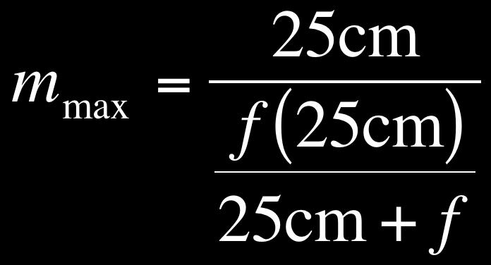
6 Simple Magnifier Because these angles are so small we can make the small angle approximation: The max magnification becomes:

7 Canceling out the 25cm gives us: Simple Magnifier With a single converging lens, it is possible to achieve angular magnification up to about 4 without serious aberrations. With multiple lenses, magnifications of up to about 20 can be achieved.
8 Compound Microscope A compound microscope consists of two lenses separated by a distance L. It gives greater magnification than a single lens. The lens closest to the object is labeled the objective lens and the lens closest to the eye is labeled the eyepiece. The objective lens has a short focal length to produce a real image.
9 Compound Microscope The goal is to place the image from the objective lens just inside the near focal point for the eyepiece. This creates a final virtual image that is inverted and very much enlarged compared to the original object. You will use the same approach for this as you did two lens systems.
10 Compound Microscope The magnification of the objective lens will be given by (also called the lateral magnification), M l, is: The magnification of the eyepiece will work as a simple magnifier such that: m e = θ θ ο 25 cm f e M l = q 1 p 1 = L f e f o L f o
11 Compound Microscope Thus, the overall magnification given by the microscope of the original object will be: m tot = m e M l = The ability of an optical microscope to view an object depends on the size of the object relative to the wavelength of light used to observe it. 25 cm f e L f e f o 25 cm f e L f o
 Reflection: Those telescopes that use a curved mirror and a lens to form an image.")
12 Telescopes There are many varieties of telescopes but they can be broken down into two types: 1) Refraction: Those telescopes that use combinations of lenses to form an image. 2) Reflection: Those telescopes that use a curved mirror and a lens to form an image. Whichever type they are, they still use the basic principle that the image of the first optical element becomes the object of the second optical element.
13 Telescopes For refracting telescopes, the two lenses are oriented such that the objective lens forms a real, inverted image of a very distant object This image will be very close to the focal point of the eyepiece. The length of the telescope tube will essentially be the addition of the two focal lengths: L f o + f e
14 Telescopes The eyepiece will then form a virtual image of this object. It will be enlarged and inverted compared to the original object. The angular magnification will be given by:

15 Telescopes For reflecting telescopes, mirrors reflect light so that they may be viewed by the observer. To the right is a Newtonian telescope, the incoming rays are reflected from the mirror and converge toward point A. A small flat mirror, M, reflects the light toward an opening in the side and passes into an eyepiece.
16 Resolution The ability of an optical system to distinguish between closely spaced objects is limited due to the wave nature of light. If two sources of light are close together, they can be treated as non-coherent sources. Since we are looking through an opening, diffraction can occur where the images consist of bright central regions flanked by weaker bright and dark rings. If the two sources are separated so that their central maxima do not overlap, their images are said to be resolved.
17 Resolution The limiting condition for resolution is called Rayleigh s Criterion: When the central maximum of one image falls on the first minimum of another image, the images are said to be just resolved. The images are just resolved if their angular separation satisfies Rayleigh s criterion.
18 Resolution If viewed through a slit of width, a, and applying Rayleigh s criterion, the limiting angle of resolution is: For the images to be resolved, the angle subtended by the two sources at the slit must be greater than θ min. For a circular opening of diameter D:
19 Clicker Question 25B-1 Two campers wish to start a fire during the day. One camper is nearsighted and one is farsighted. Whose glasses should be used to focus the Sun s rays onto to some paper to start the fire? A) The nearsighted camper. B) The farsighted camper. C) Either camper. D) Neither camper.
20 Clicker Question 25B-2 For a person with normal vision their near and far points will most likely be: A) 5 centimeters and infinity, respectively. B) 1 meter and infinity, respectively. C) 25 centimeters and infinity, respectively. D) 5 centimeters and 1 meter, respectively. E) 1 meter and 100 meters, respectively.
21 For Next Time (FNT) Keep reading Chapter 25 Start working on the homework for Chapter 24
Chapter 25. Optical Instruments
 Chapter 25 Optical Instruments Optical Instruments Analysis generally involves the laws of reflection and refraction Analysis uses the procedures of geometric optics To explain certain phenomena, the wave
There is a range of distances over which objects will be in focus; this is called the depth of field of the lens. Objects closer or farther are
 Chapter 25 Optical Instruments Some Topics in Chapter 25 Cameras The Human Eye; Corrective Lenses Magnifying Glass Telescopes Compound Microscope Aberrations of Lenses and Mirrors Limits of Resolution
Lecture Outline Chapter 27. Physics, 4 th Edition James S. Walker. Copyright 2010 Pearson Education, Inc.
 Lecture Outline Chapter 27 Physics, 4 th Edition James S. Walker Chapter 27 Optical Instruments Units of Chapter 27 The Human Eye and the Camera Lenses in Combination and Corrective Optics The Magnifying
Lecture 21. Physics 1202: Lecture 21 Today s Agenda
 Physics 1202: Lecture 21 Today s Agenda Announcements: Team problems today Team 14: Gregory Desautels, Benjamin Hallisey, Kyle Mcginnis Team 15: Austin Dion, Nicholas Gandza, Paul Macgillis-Falcon Homework
Reading: Lenses and Mirrors; Applications Key concepts: Focal points and lengths; real images; virtual images; magnification; angular magnification.
 Reading: Lenses and Mirrors; Applications Key concepts: Focal points and lengths; real images; virtual images; magnification; angular magnification. 1.! Questions about objects and images. Can a virtual
PHYSICS. Chapter 35 Lecture FOR SCIENTISTS AND ENGINEERS A STRATEGIC APPROACH 4/E RANDALL D. KNIGHT
 PHYSICS FOR SCIENTISTS AND ENGINEERS A STRATEGIC APPROACH 4/E Chapter 35 Lecture RANDALL D. KNIGHT Chapter 35 Optical Instruments IN THIS CHAPTER, you will learn about some common optical instruments and
Chapter 25 Optical Instruments
 Chapter 25 Optical Instruments Units of Chapter 25 Cameras, Film, and Digital The Human Eye; Corrective Lenses Magnifying Glass Telescopes Compound Microscope Aberrations of Lenses and Mirrors Limits of
Chapter 36. Image Formation
 Chapter 36 Image Formation Image of Formation Images can result when light rays encounter flat or curved surfaces between two media. Images can be formed either by reflection or refraction due to these
University of Rochester Department of Physics and Astronomy Physics123, Spring Homework 5 - Solutions
 Problem 5. University of Rochester Department of Physics and Astronomy Physics23, Spring 202 Homework 5 - Solutions An optometrist finds that a farsighted person has a near point at 25 cm. a) If the eye
Chapter 36. Image Formation
 Chapter 36 Image Formation Notation for Mirrors and Lenses The object distance is the distance from the object to the mirror or lens Denoted by p The image distance is the distance from the image to the
Chapter 24 Geometrical Optics. Copyright 2010 Pearson Education, Inc.
 Chapter 24 Geometrical Optics Lenses convex (converging) concave (diverging) Mirrors Ray Tracing for Mirrors We use three principal rays in finding the image produced by a curved mirror. The parallel ray
Phy Ph s y 102 Lecture Lectur 21 Optical instruments 1
 Phys 102 Lecture 21 Optical instruments 1 Today we will... Learn how combinations of lenses form images Thin lens equation & magnification Learn about the compound microscope Eyepiece & objective Total
General Physics II. Optical Instruments
 General Physics II Optical Instruments 1 The Thin-Lens Equation 2 The Thin-Lens Equation Using geometry, one can show that 1 1 1 s+ =. s' f The magnification of the lens is defined by For a thin lens,
Option G 2: Lenses. The diagram below shows the image of a square grid as produced by a lens that does not cause spherical aberration.
 Name: Date: Option G 2: Lenses 1. This question is about spherical aberration. The diagram below shows the image of a square grid as produced by a lens that does not cause spherical aberration. In the
Physics 1202: Lecture 19 Today s Agenda
 Physics 1202: Lecture 19 Today s Agenda Announcements: Team problems today Team 12: Kervell Baird, Matthew George, Derek Schultz Team 13: Paxton Stowik, Stacey Ann Burke Team 14: Gregory Desautels, Benjamin
Phys 102 Lecture 21 Optical instruments
 Phys 102 Lecture 21 Optical instruments 1 Today we will... Learn how combinations of lenses form images Thin lens equation & magnification Learn about the compound microscope Eyepiece & objective Total
Chapter 2 - Geometric Optics
 David J. Starling Penn State Hazleton PHYS 214 The human eye is a visual system that collects light and forms an image on the retina. The human eye is a visual system that collects light and forms an image
Applications of Optics
 Nicholas J. Giordano www.cengage.com/physics/giordano Chapter 26 Applications of Optics Marilyn Akins, PhD Broome Community College Applications of Optics Many devices are based on the principles of optics
Physics 1520, Spring 2013 Quiz 2, Form: A
 Physics 1520, Spring 2013 Quiz 2, Form: A Name: Date: Section 1. Exercises 1. The index of refraction of a certain type of glass for red light is 1.52. For violet light, it is 1.54. Which color of light,
PHYS 202 OUTLINE FOR PART III LIGHT & OPTICS
 PHYS 202 OUTLINE FOR PART III LIGHT & OPTICS Electromagnetic Waves A. Electromagnetic waves S-23,24 1. speed of waves = 1/( o o ) ½ = 3 x 10 8 m/s = c 2. waves and frequency: the spectrum (a) radio red
PHY 1160C Homework Chapter 26: Optical Instruments Ch 26: 2, 3, 5, 9, 13, 15, 20, 25, 27
 PHY 60C Homework Chapter 26: Optical Instruments Ch 26: 2, 3, 5, 9, 3, 5, 20, 25, 27 26.2 A pin-hole camera is used to take a photograph of a student who is.8 m tall. The student stands 2.7 m in front
INTRODUCTION THIN LENSES. Introduction. given by the paraxial refraction equation derived last lecture: Thin lenses (19.1) = 1. Double-lens systems
 = 1. Double-lens systems") Chapter 9 OPTICAL INSTRUMENTS Introduction Thin lenses Double-lens systems Aberrations Camera Human eye Compound microscope Summary INTRODUCTION Knowledge of geometrical optics, diffraction and interference,
Chapter 9 OPTICAL INSTRUMENTS Introduction Thin lenses Double-lens systems Aberrations Camera Human eye Compound microscope Summary INTRODUCTION Knowledge of geometrical optics, diffraction and interference,
Physics Chapter Review Chapter 25- The Eye and Optical Instruments Ethan Blitstein
 Physics Chapter Review Chapter 25- The Eye and Optical Instruments Ethan Blitstein The Human Eye As light enters through the human eye it first passes through the cornea (a thin transparent membrane of
Physics 222, October 25
 Physics 222, October 25 Key Concepts: Image formation by refraction Thin lenses The eye Optical instruments A single flat interface Images can be formed by refraction, when light traverses a boundary between
Physics 102: Lecture 19 Lenses and your EYE Ciliary Muscles
 Physics 02: Lecture 9 Lenses and your EYE Ciliary Muscles Physics 02: Lecture 9, Slide 3 Cases for Converging Lenses Object Past 2F Image Inverted Reduced Real Object Between F & 2F Image Inverted Enlarged
Physics 208 Spring 2008 Lab 2: Lenses and the eye
 Name Section Physics 208 Spring 2008 Lab 2: Lenses and the eye Your TA will use this sheet to score your lab. It is to be turned in at the end of lab. You must use complete sentences and clearly explain
Lecture PowerPoint. Chapter 25 Physics: Principles with Applications, 6 th edition Giancoli
 Lecture PowerPoint Chapter 25 Physics: Principles with Applications, 6 th edition Giancoli 2005 Pearson Prentice Hall This work is protected by United States copyright laws and is provided solely for the
Chapter 34: Geometrical Optics (Part 2)
") Chapter 34: Geometrical Optics (Part 2) Brief review Optical instruments Camera Human eye Magnifying glass Telescope Microscope Optical Aberrations Phys Phys 2435: 22: Chap. 34, 31, Pg 1 The Lens Equation
Chapter 34: Geometrical Optics (Part 2) Brief review Optical instruments Camera Human eye Magnifying glass Telescope Microscope Optical Aberrations Phys Phys 2435: 22: Chap. 34, 31, Pg 1 The Lens Equation
Dr. Todd Satogata (ODU/Jefferson Lab) Monday, April
 Monday, April") University Physics 227N/232N Mirrors and Lenses Homework Optics 2 due Friday AM Quiz Friday Optional review session next Monday (Apr 28) Bring Homework Notebooks to Final for Grading Dr. Todd Satogata
University Physics 227N/232N Mirrors and Lenses Homework Optics 2 due Friday AM Quiz Friday Optional review session next Monday (Apr 28) Bring Homework Notebooks to Final for Grading Dr. Todd Satogata
Physics 6C. Cameras and the Human Eye. Prepared by Vince Zaccone For Campus Learning Assistance Services at UCSB
 Physics 6C Cameras and the Human Eye CAMERAS A typical camera uses a converging lens to focus a real (inverted) image onto photographic film (or in a digital camera the image is on a CCD chip). Light goes
Chapter 34 Geometric Optics
 Chapter 34 Geometric Optics Lecture by Dr. Hebin Li Goals of Chapter 34 To see how plane and curved mirrors form images To learn how lenses form images To understand how a simple image system works Reflection
Chapter 36. Image Formation
 Chapter 36 Image Formation Image of Formation Images can result when light rays encounter flat or curved surfaces between two media. Images can be formed either by reflection or refraction due to these
PHYSICS FOR THE IB DIPLOMA CAMBRIDGE UNIVERSITY PRESS
 Option C Imaging C Introduction to imaging Learning objectives In this section we discuss the formation of images by lenses and mirrors. We will learn how to construct images graphically as well as algebraically.
Activity 6.1 Image Formation from Spherical Mirrors
 PHY385H1F Introductory Optics Practicals Day 6 Telescopes and Microscopes October 31, 2011 Group Number (number on Intro Optics Kit):. Facilitator Name:. Record-Keeper Name: Time-keeper:. Computer/Wiki-master:..
Laboratory 7: Properties of Lenses and Mirrors
 Laboratory 7: Properties of Lenses and Mirrors Converging and Diverging Lens Focal Lengths: A converging lens is thicker at the center than at the periphery and light from an object at infinity passes
Readings: Hecht, Chapter 24
 5. GEOMETRIC OPTICS Readings: Hecht, Chapter 24 Introduction In this lab you will measure the index of refraction of glass using Snell s Law, study the application of the laws of geometric optics to systems
G1 THE NATURE OF EM WAVES AND LIGHT SOURCES
 G1 THE NATURE OF EM WAVES AND LIGHT SOURCES G2 OPTICAL INSTRUMENTS HW/Study Packet Required: READ Tsokos, pp 598-620 SL/HL Supplemental: Hamper, pp 411-450 DO Questions p 605 #1,3 pp 621-623 #6,8,15,18,19,24,26
O5: Lenses and the refractor telescope
 O5. 1 O5: Lenses and the refractor telescope Introduction In this experiment, you will study converging lenses and the lens equation. You will make several measurements of the focal length of lenses and
Chapter 3 Op,cal Instrumenta,on
 Imaging by an Op,cal System Change in curvature of wavefronts by a thin lens Chapter 3 Op,cal Instrumenta,on 3-1 Stops, Pupils, and Windows 3-4 The Camera 3-5 Simple Magnifiers and Eyepieces 1. Magnifiers
LAB 12 Reflection and Refraction
 Cabrillo College Physics 10L Name LAB 12 Reflection and Refraction Read Hewitt Chapters 28 and 29 What to learn and explore Please read this! When light rays reflect off a mirror surface or refract through
Average: Standard Deviation: Max: 99 Min: 40
 1 st Midterm Exam Average: 83.1 Standard Deviation: 12.0 Max: 99 Min: 40 Please contact me to fix an appointment, if you took less than 65. Chapter 33 Lenses and Op/cal Instruments Units of Chapter 33
Chapter 25: Applied Optics. PHY2054: Chapter 25
 Chapter 25: Applied Optics PHY2054: Chapter 25 1 Operation of the Eye 24 mm PHY2054: Chapter 25 2 Essential parts of the eye Cornea transparent outer structure Pupil opening for light Lens partially focuses
Converging and Diverging Surfaces. Lenses. Converging Surface
 Lenses Sandy Skoglund 2 Converging and Diverging s AIR Converging If the surface is convex, it is a converging surface in the sense that the parallel rays bend toward each other after passing through the
Life Science Chapter 2 Study Guide
 Key concepts and definitions Waves and the Electromagnetic Spectrum Wave Energy Medium Mechanical waves Amplitude Wavelength Frequency Speed Properties of Waves (pages 40-41) Trough Crest Hertz Electromagnetic
The eye & corrective lenses
 Phys 102 Lecture 20 The eye & corrective lenses 1 Today we will... Apply concepts from ray optics & lenses Simple optical instruments the camera & the eye Learn about the human eye Accommodation Myopia,
Geometric!Op9cs! Reflec9on! Refrac9on!`!Snell s!law! Mirrors!and!Lenses! Other!topics! Thin!Lens!Equa9on! Magnifica9on! Lensmaker s!formula!
 Geometric!Op9cs! Reflec9on! Refrac9on!`!Snell s!law! Mirrors!and!Lenses! Thin!Lens!Equa9on! Magnifica9on! Lensmaker s!formula! Other!topics! Telescopes! Apertures! Reflec9on! Angle!of!incidence!equals!angle!of!reflec9on!
Types of lenses. Shown below are various types of lenses, both converging and diverging.
 Types of lenses Shown below are various types of lenses, both converging and diverging. Any lens that is thicker at its center than at its edges is a converging lens with positive f; and any lens that
Chapter 34. Images. Copyright 2014 John Wiley & Sons, Inc. All rights reserved.
 Chapter 34 Images Copyright 34-1 Images and Plane Mirrors Learning Objectives 34.01 Distinguish virtual images from real images. 34.02 Explain the common roadway mirage. 34.03 Sketch a ray diagram for
13. Optical Instruments*
 13. Optical Instruments* Objective: Here what you have been learning about thin lenses is applied to make a telescope. In the process you encounter general optical instrument design concepts. The learning
General Physics Experiment 5 Optical Instruments: Simple Magnifier, Microscope, and Newtonian Telescope
 General Physics Experiment 5 Optical Instruments: Simple Magnifier, Microscope, and Newtonian Telescope Objective: < To observe the magnifying properties of the simple magnifier, the microscope and the
Physics 1C Lecture 27B
 Physics 1C Lecture 27B Single Slit Interference! Example! Light of wavelength 750nm passes through a slit 1.00μm wide. How wide is the central maximum in centimeters, in a Fraunhofer diffraction pattern
Chapter 3 Op+cal Instrumenta+on
 Chapter 3 Op+cal Instrumenta+on 3-1 Stops, Pupils, and Windows 3-4 The Camera 3-5 Simple Magnifiers and Eyepieces 3-6 Microscopes 3-7 Telescopes Today (2011-09-22) 1. Magnifiers 2. Camera 3. Resolution
Lecture 17. Image formation Ray tracing Calculation. Lenses Convex Concave. Mirrors Convex Concave. Optical instruments
 Lecture 17. Image formation Ray tracing Calculation Lenses Convex Concave Mirrors Convex Concave Optical instruments Image formation Laws of refraction and reflection can be used to explain how lenses
Geometric Optics. Ray Model. assume light travels in straight line uses rays to understand and predict reflection & refraction
 Geometric Optics Ray Model assume light travels in straight line uses rays to understand and predict reflection & refraction General Physics 2 Geometric Optics 1 Reflection Law of reflection the angle
Physics 132: Lecture Fundamentals of Physics
 Physics 132: Lecture Fundamentals of Physics II Agenda for Today Mirrors Concave Convex e Mirror equation Physics 201: Lecture 1, Pg 1 Curved mirrors A Spherical Mirror: section of a sphere. R light ray
Chapter 29/30. Wave Fronts and Rays. Refraction of Sound. Dispersion in a Prism. Index of Refraction. Refraction and Lenses
 Chapter 29/30 Refraction and Lenses Refraction Refraction the bending of waves as they pass from one medium into another. Caused by a change in the average speed of light. Analogy A car that drives off
Chapter 23. Mirrors and Lenses
 Chapter 23 Mirrors and Lenses Mirrors and Lenses The development of mirrors and lenses aided the progress of science. It led to the microscopes and telescopes. Allowed the study of objects from microbes
THIN LENSES: APPLICATIONS
 THIN LENSES: APPLICATIONS OBJECTIVE: To see how thin lenses are used in three important cases: the eye, the telescope and the microscope. Part 1: The Eye and Visual Acuity THEORY: We can think of light
30 Lenses. Lenses change the paths of light.
 Lenses change the paths of light. A light ray bends as it enters glass and bends again as it leaves. Light passing through glass of a certain shape can form an image that appears larger, smaller, closer,
Test Review # 8. Physics R: Form TR8.17A. Primary colors of light
 Physics R: Form TR8.17A TEST 8 REVIEW Name Date Period Test Review # 8 Light and Color. Color comes from light, an electromagnetic wave that travels in straight lines in all directions from a light source
Light: Lenses and. Mirrors. Test Date: Name 1ÿ-ÿ. Physics. Light: Lenses and Mirrors
 Name 1ÿ-ÿ Physics Light: Lenses and Mirrors i Test Date: "Shadows cannot see themselves in the mirror of the sun." -Evita Peron What are lenses? Lenses are made from transparent glass or plastice and refract
Chapter 18 Optical Elements
 Chapter 18 Optical Elements GOALS When you have mastered the content of this chapter, you will be able to achieve the following goals: Definitions Define each of the following terms and use it in an operational
Geometric Optics. Objective: To study the basics of geometric optics and to observe the function of some simple and compound optical devices.
 Geometric Optics Objective: To study the basics of geometric optics and to observe the function of some simple and compound optical devices. Apparatus: Pasco optical bench, mounted lenses (f= +100mm, +200mm,
Physics II. Chapter 23. Spring 2018
 Physics II Chapter 23 Spring 2018 IMPORTANT: Except for multiple-choice questions, you will receive no credit if you show only an answer, even if the answer is correct. Always show in the space on your
SUBJECT: PHYSICS. Use and Succeed.
 SUBJECT: PHYSICS I hope this collection of questions will help to test your preparation level and useful to recall the concepts in different areas of all the chapters. Use and Succeed. Navaneethakrishnan.V
Chapter 26. The Refraction of Light: Lenses and Optical Instruments
 Chapter 26 The Refraction of Light: Lenses and Optical Instruments 26.1 The Index of Refraction Light travels through a vacuum at a speed c=3. 00 10 8 m/ s Light travels through materials at a speed less
MULTIPLE CHOICE. Choose the one alternative that best completes the statement or answers the question.
 Exam Name MULTIPLE CHOICE. Choose the one alternative that best completes the statement or answers the question. 1) A plane mirror is placed on the level bottom of a swimming pool that holds water (n =
Lab 12. Optical Instruments
 Lab 12. Optical Instruments Goals To construct a simple telescope with two positive lenses having known focal lengths, and to determine the angular magnification (analogous to the magnifying power of a
Geometric Optics. This is a double-convex glass lens mounted in a wooden frame. We will use this as the eyepiece for our microscope.
 I. Before you come to lab Read through this handout in its entirety. II. Learning Objectives As a result of performing this lab, you will be able to: 1. Use the thin lens equation to determine the focal
Unit 3: Energy On the Move
 14 14 Table of Contents Unit 3: Energy On the Move Chapter 14: Mirrors and Lenses 14.1: Mirrors 14.2: Lenses 14.3: Optical Instruments 14.1 Mirrors How do you use light to see? When light travels from
PHYS 160 Astronomy. When analyzing light s behavior in a mirror or lens, it is helpful to use a technique called ray tracing.
 Optics Introduction In this lab, we will be exploring several properties of light including diffraction, reflection, geometric optics, and interference. There are two sections to this lab and they may
25 cm. 60 cm. 50 cm. 40 cm.
 Geometrical Optics 7. The image formed by a plane mirror is: (a) Real. (b) Virtual. (c) Erect and of equal size. (d) Laterally inverted. (e) B, c, and d. (f) A, b and c. 8. A real image is that: (a) Which
Chapter 23. Mirrors and Lenses
 Chapter 23 Mirrors and Lenses Notation for Mirrors and Lenses The object distance is the distance from the object to the mirror or lens Denoted by p The image distance is the distance from the image to
CH. 23 Mirrors and Lenses HW# 6, 7, 9, 11, 13, 21, 25, 31, 33, 35
 CH. 23 Mirrors and Lenses HW# 6, 7, 9, 11, 13, 21, 25, 31, 33, 35 Mirrors Rays of light reflect off of mirrors, and where the reflected rays either intersect or appear to originate from, will be the location
Physics 197 Lab 7: Thin Lenses and Optics
 Physics 197 Lab 7: Thin Lenses and Optics Equipment: Item Part # Qty per Team # of Teams Basic Optics Light Source PASCO OS-8517 1 12 12 Power Cord for Light Source 1 12 12 Ray Optics Set (Concave Lens)
Applied Optics. , Physics Department (Room #36-401) , ,
 , ,") Applied Optics Professor, Physics Department (Room #36-401) 2290-0923, 019-539-0923, shsong@hanyang.ac.kr Office Hours Mondays 15:00-16:30, Wednesdays 15:00-16:30 TA (Ph.D. student, Room #36-415) 2290-0921,
Applied Optics Professor, Physics Department (Room #36-401) 2290-0923, 019-539-0923, shsong@hanyang.ac.kr Office Hours Mondays 15:00-16:30, Wednesdays 15:00-16:30 TA (Ph.D. student, Room #36-415) 2290-0921,
Waves & Oscillations
 Physics 42200 Waves & Oscillations Lecture 27 Geometric Optics Spring 205 Semester Matthew Jones Sign Conventions > + = Convex surface: is positive for objects on the incident-light side is positive for
Determination of Focal Length of A Converging Lens and Mirror
 Physics 41 Determination of Focal Length of A Converging Lens and Mirror Objective: Apply the thin-lens equation and the mirror equation to determine the focal length of a converging (biconvex) lens and
Optical Systems. The normal eye
 Optical Systems The normal eye The ciliary muscles can adjust the shape of the lens of the human eye. As the eye attempts to see objects at different distances, the muscles will adjust the focal length
Exam 3--PHYS 2021M-Spring 2009
 Name: Class: Date: Exam 3--PHYS 2021M-Spring 2009 Multiple Choice Identify the choice that best completes the statement or answers the question Each question is worth 2 points 1 Images made by mirrors
Physics 228 Lecture 3. Today: Spherical Mirrors Lenses.
 Physics 228 Lecture 3 Today: Spherical Mirrors Lenses www.physics.rutgers.edu/ugrad/228 a) Santa as he sees himself in a mirrored sphere. b) Santa as he sees himself in a flat mirror after too much eggnog.
Physics 11. Unit 8 Geometric Optics Part 2
 Physics 11 Unit 8 Geometric Optics Part 2 (c) Refraction (i) Introduction: Snell s law Like water waves, when light is traveling from one medium to another, not only does its wavelength, and in turn the
Practice Problems for Chapter 25-26
 Practice Problems for Chapter 25-26 1. What are coherent waves? 2. Describe diffraction grating 3. What are interference fringes? 4. What does monochromatic light mean? 5. What does the Rayleigh Criterion
!"#$%&$'()(*'+,&-./,'(0' focal point! parallel rays! converging lens" image of an object in a converging lens" converging lens: 3 easy rays" !
(*'+,&-./,'(0' focal point! parallel rays! converging lens image of an object in a converging lens converging lens: 3 easy rays !") !"#$%&$'()(*'+,&-./,'(0' converging lens"! +,7$,$'! 8,9/4&:27'473'+,7$,$'! 84#';%4?.4:27' 1234#5$'126%&$'''! @4=,/4$'! 1",'A.=47'>#,*'+,7$,$'473'B4
!"#$%&$'()(*'+,&-./,'(0' converging lens"! +,7$,$'! 8,9/4&:27'473'+,7$,$'! 84#';%4?.4:27' 1234#5$'126%&$'''! @4=,/4$'! 1",'A.=47'>#,*'+,7$,$'473'B4
b) (4) If you could look at a snapshot of the waves, how far apart in space are two successive positive peaks of the electric field?
 (4) If you could look at a snapshot of the waves, how far apart in space are two successive positive peaks of the electric field?") General Physics II Exam 3 - Chs. 22 25 - EM Waves & Optics October 20, 206 Name Rec. Instr. Rec. Time For full credit, make your work clear. Show formulas used, essential steps, and results with correct
General Physics II Exam 3 - Chs. 22 25 - EM Waves & Optics October 20, 206 Name Rec. Instr. Rec. Time For full credit, make your work clear. Show formulas used, essential steps, and results with correct
Chapter 34 The Wave Nature of Light; Interference. Copyright 2009 Pearson Education, Inc.
 Chapter 34 The Wave Nature of Light; Interference 34-7 Luminous Intensity The intensity of light as perceived depends not only on the actual intensity but also on the sensitivity of the eye at different
Mirrors and Lenses. Images can be formed by reflection from mirrors. Images can be formed by refraction through lenses.
 Mirrors and Lenses Images can be formed by reflection from mirrors. Images can be formed by refraction through lenses. Notation for Mirrors and Lenses The object distance is the distance from the object
CHAPTER 18 REFRACTION & LENSES
 Physics Approximate Timeline Students are expected to keep up with class work when absent. CHAPTER 18 REFRACTION & LENSES Day Plans for the day Assignments for the day 1 18.1 Refraction of Light o Snell
LECTURE 17 MIRRORS AND THIN LENS EQUATION
 LECTURE 17 MIRRORS AND THIN LENS EQUATION 18.6 Image formation with spherical mirrors Concave mirrors Convex mirrors 18.7 The thin-lens equation Sign conventions for lenses and mirrors Spherical mirrors
Geometric Optics Practice Problems. Ray Tracing - Draw at least two principle rays and show the image created by the lens or mirror.
 Geometric Optics Practice Problems Ray Tracing - Draw at least two principle rays and show the image created by the lens or mirror. 1. 2. 3. 4. 5. 6. 7. 8. 9. 10. Practice Problems - Mirrors Classwork
mirrors and lenses PHY232 Remco Zegers Room W109 cyclotron building
 mirrors and lenses PHY232 Remco Zegers zegers@nscl.msu.edu Room W109 cyclotron building http://www.nscl.msu.edu/~zegers/phy232.html quiz (extra credit) a ray of light moves from air to a material with
12:40-2:40 3:00-4:00 PM
 Physics 294H l Professor: Joey Huston l email:huston@msu.edu l office: BPS3230 l Homework will be with Mastering Physics (and an average of 1 hand-written problem per week) Help-room hours: 12:40-2:40
Notation for Mirrors and Lenses. Chapter 23. Types of Images for Mirrors and Lenses. More About Images
 Notation for Mirrors and Lenses Chapter 23 Mirrors and Lenses Sections: 4, 6 Problems:, 8, 2, 25, 27, 32 The object distance is the distance from the object to the mirror or lens Denoted by p The image
Unit 2: Optics Part 2
 Unit 2: Optics Part 2 Refraction of Visible Light 1. Bent-stick effect: When light passes from one medium to another (for example, when a beam of light passes through air and into water, or vice versa),
King Saud University College of Science Physics & Astronomy Dept.
 King Saud University College of Science Physics & Astronomy Dept. PHYS 111 (GENERAL PHYSICS 2) CHAPTER 36: Image Formation LECTURE NO. 9 Presented by Nouf Saad Alkathran 36.1 Images Formed by Flat Mirrors
Geometrical Optics Optical systems
 Phys 322 Lecture 16 Chapter 5 Geometrical Optics Optical systems Magnifying glass Purpose: enlarge a nearby object by increasing its image size on retina Requirements: Image should not be inverted Image
Spherical Mirrors. Concave Mirror, Notation. Spherical Aberration. Image Formed by a Concave Mirror. Image Formed by a Concave Mirror 4/11/2014
 Notation for Mirrors and Lenses Chapter 23 Mirrors and Lenses The object distance is the distance from the object to the mirror or lens Denoted by p The image distance is the distance from the image to
Test Review # 9. Physics R: Form TR9.15A. Primary colors of light
 Physics R: Form TR9.15A TEST 9 REVIEW Name Date Period Test Review # 9 Light and Color. Color comes from light, an electromagnetic wave that travels in straight lines in all directions from a light source
THE TELESCOPE. PART 1: The Eye and Visual Acuity
 THE TELESCOPE OBJECTIVE: As seen with the naked eye the heavens are a wonderfully fascinating place. With a little careful watching the brighter stars can be grouped into constellations and an order seen
[ Summary. 3i = 1* 6i = 4J;
 the projections at angle 2. We calculate the difference between the measured projections at angle 2 (6 and 14) and the projections based on the previous esti mate (top row: 2>\ + 6\ = 10; same for bottom