CH. 23 Mirrors and Lenses HW# 6, 7, 9, 11, 13, 21, 25, 31, 33, 35
|
|
|
- Bruno Sanders
- 6 years ago
- Views:
Transcription
1 CH. 23 Mirrors and Lenses HW# 6, 7, 9, 11, 13, 21, 25, 31, 33, 35
2 Mirrors Rays of light reflect off of mirrors, and where the reflected rays either intersect or appear to originate from, will be the location of the image. Real image light actually passes through the image point. Virtual image light appears to come from the image point. Different situations will yield real or virtual images.
3 Mirrors are commonly made of a piece of glass with a thin reflective metal coating on the back side. (sometimes a layer of silver) If you scratch away the metal coating you just have piece of glass. Some light reflects off the front surface of the glass. The rest of the light passes through the glass before reflecting off the metal and going back through the mirror. See how a rearview mirror works with a day and night setting. fig. 23.5
4 For a flat mirror: Magnification: M = image height/object height = h /h M = 1 The image appears as far behind the mirror as the object is in front. Image distance/object distance = Image height/object height The image is unmagnified (M=1), virtual and upright (not flipped upside down) fig. 23.2
5 Spherical Mirrors Spherical mirrors have the shape of a segment of a sphere. In 2-D we will treat them as a segment of a circle. Concave mirror the reflective surface is on the inner side of the mirror. Figure 23.7 Convex mirror the reflective surface is on the outer side of the mirror.
6 Spherical mirrors have an axis of symmetry. The principle axis is a line drawn through this line of symmetry, through the center of the mirror. We will use an approximation where we only use rays of light that make small angles with the principle axis. Rays that make large angles with the principle axis produce an effect called spherical aberration. Produce a blurry image because the rays are not reflected to the exact same location. figure 23.8
7 Spherical Mirrors M = h /h = -q/p (q = image length p = object length) Mirror equation 1/p + 1/q = 2/R R = radius of curvature of mirror When p is very large(approaches infinity) 1/p =0 Then the image is at q = R/2 The incoming rays are essentially parallel and are focused at the image location. (fig ) This point is called the focal point, f f= R/2
8
9 Convex mirror: Silvered so the light is reflected from the outer side of the mirror. Also called a diverging mirror. Mirror equation is still true for convex mirrors. fig For a convex mirror, the center of the circle, and thus the focal point, are both behind the mirror. (Opposite side of mirrors from the object)
10 Table 23.1 Sign Conventions for Mirrors If p, q, and f are in front of the mirror, they are positive. If in back, negative. If the image is upright, positive image height. If image is inverted, negative image height. The big difference between concave and convex mirrors is that concave mirrors have a positive focal length. Convex mirrors have a negative focal length.
11 Ray Diagrams for Mirrors Rules for drawing ray diagrams. These are all the product of the law that the angle of reflection is equal to the angle of incidence. 1)Rays drawn parallel to principle axis are reflected through the focal point. 2)Rays drawn through focal point are reflected parallel to principle axis. 3)Ray drawn through center of curvature (point C) get reflected back on itself. 4)Also can see that a ray incident at the center of the mirror is reflected at an equal angle.
12 See figure Work example 23.2 This was done in the ray tracing for mirrors lab. Make these drawing neat and to scale. These drawing can be used to determine image positions and image heights if drawn correctly.
13 Images can also be formed by Refraction
14
15
16 The equation for lenses is the same as the equation for mirrors. Rays parallel to the principle axis of a lens will converge at the focal length after passing through the lens. The focal length is the image distance that corresponds to an infinite object distance. Key difference between lenses and mirrors: Lenses have two focal points, one on each side.
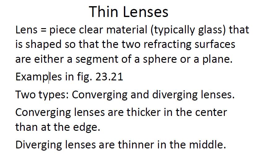
17 Converging lenses cause parallel rays to converge. Diverging lenses cause parallel rays to diverge (spread out) see fig again M = h /h = -q/p Table 23.3 has sign conventions for lenses. Converging lens has + focal length Diverging lens has focal length
18
19 Ray Diagrams for Lenses 1) If a ray comes from parallel to the principle axis, after being refracted, it will pass through the focal point behind the lens. 2) If a ray drawn through the center of the lens, it keeps going straight. 3) If a ray is drawn through the focal point in front of the lens, after going through the lens, it will refract so that it is parallel to the principle axis. Figure 23.25
20 See examples 23.7 and 23.8 Combinations of lenses. When you have multiple lenses, you can work out each lens, one at a time. The image formed by the first lens, becomes the object for the second lens. This is how some telescopes and microscopes work.
21 Lens and Mirrors Aberrations We used assumptions that the incoming rays make small angles with the principle axis. This is not always true in life. When the angles are large, the rays are not focused to the same point. Image is fuzzy. Two types of aberrations: spherical and chromatic
22 Spherical Aberration Results from the fact that the focal points of rays that are far from the principle axis are different from the focal point of rays that are near the principle axis. Has to do with the spherical shape of the lens or mirror. Figure When taking a picture, your camera can reduce this problem by having an adjustable aperture. By narrowing the aperture, you eliminate the rays that are far from the principle axis.
23 Spherical aberration in mirrors can be reduced or eliminated by using a parabolic mirror instead of a spherical mirror. All rays that are parallel to the principle axis will be reflected through the focal point. Good for telescopes, since the object is far enough away that all the rays are essentially parallel to the axis. Can be used in flashlights. Put the bulb at the focus. Then the rays are reflected off the parabolic mirror and will be parallel to the axis. Problem: High quality parabolic mirrors are expensive.
24 Chromatic Aberration White light is made up of light of different colors (wavelengths). In chapter 22 we saw that index of refraction depends on wavelength. Therefore, when different colors pass through a lens, they are focused to different points. See fig Chromatic aberration can be reduced by using the right combination of converging and diverging lenses. Takes some effort. Mirrors don t have chromatic aberration, since the law of reflection does not depend on wavelength.
Chapter 23. Mirrors and Lenses
 Chapter 23 Mirrors and Lenses Mirrors and Lenses The development of mirrors and lenses aided the progress of science. It led to the microscopes and telescopes. Allowed the study of objects from microbes
Notation for Mirrors and Lenses. Chapter 23. Types of Images for Mirrors and Lenses. More About Images
 Notation for Mirrors and Lenses Chapter 23 Mirrors and Lenses Sections: 4, 6 Problems:, 8, 2, 25, 27, 32 The object distance is the distance from the object to the mirror or lens Denoted by p The image
Chapter 23. Mirrors and Lenses
 Chapter 23 Mirrors and Lenses Notation for Mirrors and Lenses The object distance is the distance from the object to the mirror or lens Denoted by p The image distance is the distance from the image to
Spherical Mirrors. Concave Mirror, Notation. Spherical Aberration. Image Formed by a Concave Mirror. Image Formed by a Concave Mirror 4/11/2014
 Notation for Mirrors and Lenses Chapter 23 Mirrors and Lenses The object distance is the distance from the object to the mirror or lens Denoted by p The image distance is the distance from the image to
Chapter 23. Mirrors and Lenses
 Chapter 23 Mirrors and Lenses Notation for Mirrors and Lenses The object distance is the distance from the object to the mirror or lens Denoted by p The image distance is the distance from the image to
Optics Practice. Version #: 0. Name: Date: 07/01/2010
 Optics Practice Date: 07/01/2010 Version #: 0 Name: 1. Which of the following diagrams show a real image? a) b) c) d) e) i, ii, iii, and iv i and ii i and iv ii and iv ii, iii and iv 2. A real image is
Chapter 23. Geometrical Optics: Mirrors and Lenses and other Instruments
 Chapter 23 Geometrical Optics: Mirrors and Lenses and other Instruments HITT 1 You stand two feet away from a plane mirror. How far is it from you to your image? a. 2.0 ft b. 3.0 ft c. 4.0 ft d. 5.0 ft
Mirrors and Lenses. Images can be formed by reflection from mirrors. Images can be formed by refraction through lenses.
 Mirrors and Lenses Images can be formed by reflection from mirrors. Images can be formed by refraction through lenses. Notation for Mirrors and Lenses The object distance is the distance from the object
Chapter 36. Image Formation
 Chapter 36 Image Formation Real and Virtual Images Real images can be displayed on screens Virtual Images can not be displayed onto screens. Focal Length& Radius of Curvature When the object is very far
PHYS 160 Astronomy. When analyzing light s behavior in a mirror or lens, it is helpful to use a technique called ray tracing.
 Optics Introduction In this lab, we will be exploring several properties of light including diffraction, reflection, geometric optics, and interference. There are two sections to this lab and they may
Physics II. Chapter 23. Spring 2018
 Physics II Chapter 23 Spring 2018 IMPORTANT: Except for multiple-choice questions, you will receive no credit if you show only an answer, even if the answer is correct. Always show in the space on your
Image Formation. Light from distant things. Geometrical optics. Pinhole camera. Chapter 36
 Light from distant things Chapter 36 We learn about a distant thing from the light it generates or redirects. The lenses in our eyes create images of objects our brains can process. This chapter concerns
Ch 24. Geometric Optics
 text concept Ch 24. Geometric Optics Fig. 24 3 A point source of light P and its image P, in a plane mirror. Angle of incidence =angle of reflection. text. Fig. 24 4 The blue dashed line through object
Converging Lenses. Parallel rays are brought to a focus by a converging lens (one that is thicker in the center than it is at the edge).
.") Chapter 30: Lenses Types of Lenses Piece of glass or transparent material that bends parallel rays of light so they cross and form an image Two types: Converging Diverging Converging Lenses Parallel rays
Chapter 30: Lenses Types of Lenses Piece of glass or transparent material that bends parallel rays of light so they cross and form an image Two types: Converging Diverging Converging Lenses Parallel rays
Geometric Optics. Ray Model. assume light travels in straight line uses rays to understand and predict reflection & refraction
 Geometric Optics Ray Model assume light travels in straight line uses rays to understand and predict reflection & refraction General Physics 2 Geometric Optics 1 Reflection Law of reflection the angle
Chapter 23. Light Geometric Optics
 Chapter 23. Light Geometric Optics There are 3 basic ways to gather light and focus it to make an image. Pinhole - Simple geometry Mirror - Reflection Lens - Refraction Pinhole Camera Image Formation (the
mirrors and lenses PHY232 Remco Zegers Room W109 cyclotron building
 mirrors and lenses PHY232 Remco Zegers zegers@nscl.msu.edu Room W109 cyclotron building http://www.nscl.msu.edu/~zegers/phy232.html quiz (extra credit) a ray of light moves from air to a material with
Lenses. A transparent object used to change the path of light Examples: Human eye Eye glasses Camera Microscope Telescope
 SNC2D Lenses A transparent object used to change the path of light Examples: Human eye Eye glasses Camera Microscope Telescope Reading stones used by monks, nuns, and scholars ~1000 C.E. Lenses THERE ARE
Chapter 36. Image Formation
 Chapter 36 Image Formation Image of Formation Images can result when light rays encounter flat or curved surfaces between two media. Images can be formed either by reflection or refraction due to these
Mirrors, Lenses &Imaging Systems
 Mirrors, Lenses &Imaging Systems We describe the path of light as straight-line rays And light rays from a very distant point arrive parallel 145 Phys 24.1 Mirrors Standing away from a plane mirror shows
Chapter 36. Image Formation
 Chapter 36 Image Formation Notation for Mirrors and Lenses The object distance is the distance from the object to the mirror or lens Denoted by p The image distance is the distance from the image to the
NORTHERN ILLINOIS UNIVERSITY PHYSICS DEPARTMENT. Physics 211 E&M and Quantum Physics Spring Lab #8: Thin Lenses
 NORTHERN ILLINOIS UNIVERSITY PHYSICS DEPARTMENT Physics 211 E&M and Quantum Physics Spring 2018 Lab #8: Thin Lenses Lab Writeup Due: Mon/Wed/Thu/Fri, April 2/4/5/6, 2018 Background In the previous lab
Algebra Based Physics. Reflection. Slide 1 / 66 Slide 2 / 66. Slide 3 / 66. Slide 4 / 66. Slide 5 / 66. Slide 6 / 66.
 Slide 1 / 66 Slide 2 / 66 Algebra Based Physics Geometric Optics 2015-12-01 www.njctl.org Slide 3 / 66 Slide 4 / 66 Table of ontents lick on the topic to go to that section Reflection Refraction and Snell's
LECTURE 17 MIRRORS AND THIN LENS EQUATION
 LECTURE 17 MIRRORS AND THIN LENS EQUATION 18.6 Image formation with spherical mirrors Concave mirrors Convex mirrors 18.7 The thin-lens equation Sign conventions for lenses and mirrors Spherical mirrors
Chapter 18 Optical Elements
 Chapter 18 Optical Elements GOALS When you have mastered the content of this chapter, you will be able to achieve the following goals: Definitions Define each of the following terms and use it in an operational
King Saud University College of Science Physics & Astronomy Dept.
 King Saud University College of Science Physics & Astronomy Dept. PHYS 111 (GENERAL PHYSICS 2) CHAPTER 36: Image Formation LECTURE NO. 9 Presented by Nouf Saad Alkathran 36.1 Images Formed by Flat Mirrors
Final Reg Optics Review SHORT ANSWER. Write the word or phrase that best completes each statement or answers the question.
 Final Reg Optics Review 1) How far are you from your image when you stand 0.75 m in front of a vertical plane mirror? 1) 2) A object is 12 cm in front of a concave mirror, and the image is 3.0 cm in front
2015 EdExcel A Level Physics EdExcel A Level Physics. Lenses
 2015 EdExcel A Level Physics 2015 EdExcel A Level Physics Topic Topic 5 5 Lenses Types of lenses Converging lens bi-convex has two convex surfaces Diverging lens bi-concave has two concave surfaces Thin
Algebra Based Physics. Reflection. Slide 1 / 66 Slide 2 / 66. Slide 3 / 66. Slide 4 / 66. Slide 5 / 66. Slide 6 / 66.
 Slide 1 / 66 Slide 2 / 66 lgebra ased Physics Geometric Optics 2015-12-01 www.njctl.org Slide 3 / 66 Slide 4 / 66 Table of ontents lick on the topic to go to that section Reflection Refraction and Snell's
Physics 228 Lecture 3. Today: Spherical Mirrors Lenses.
 Physics 228 Lecture 3 Today: Spherical Mirrors Lenses www.physics.rutgers.edu/ugrad/228 a) Santa as he sees himself in a mirrored sphere. b) Santa as he sees himself in a flat mirror after too much eggnog.
Chapter 3 Mirrors. The most common and familiar optical device
 Chapter 3 Mirrors The most common and familiar optical device Outline Plane mirrors Spherical mirrors Graphical image construction Two mirrors; The Cassegrain Telescope Plane mirrors Common household mirrors:
28 Thin Lenses: Ray Tracing
 28 Thin Lenses: Ray Tracing A lens is a piece of transparent material whose surfaces have been shaped so that, when the lens is in another transparent material (call it medium 0), light traveling in medium
Chapter 2 - Geometric Optics
 David J. Starling Penn State Hazleton PHYS 214 The human eye is a visual system that collects light and forms an image on the retina. The human eye is a visual system that collects light and forms an image
Refraction is the when a ray changes mediums. Examples of mediums:
 Refraction and Lenses Refraction is the when a ray changes mediums. Examples of mediums: Lenses are optical devices which take advantage of the refraction of light to 1. produces images real and 2. change
Waves & Oscillations
 Physics 42200 Waves & Oscillations Lecture 27 Geometric Optics Spring 205 Semester Matthew Jones Sign Conventions > + = Convex surface: is positive for objects on the incident-light side is positive for
Academic Year: 2017/2018 Term 3 Physics - Grade 10 Revision sheet Chapter 13: section 1,2,3 / Chapter 14: section 1 pages: ( ),( )
,( )") Academic Year: 2017/2018 Term 3 Physics - Grade 10 Revision sheet Chapter 13: section 1,2,3 / Chapter 14: section 1 pages: (442-462),(482-487) Spherical curved mirrors : a mirror that has the shape of
Academic Year: 2017/2018 Term 3 Physics - Grade 10 Revision sheet Chapter 13: section 1,2,3 / Chapter 14: section 1 pages: (442-462),(482-487) Spherical curved mirrors : a mirror that has the shape of
Physics 132: Lecture Fundamentals of Physics
 Physics 132: Lecture Fundamentals of Physics II Agenda for Today Mirrors Concave Convex e Mirror equation Physics 201: Lecture 1, Pg 1 Curved mirrors A Spherical Mirror: section of a sphere. R light ray
Astronomy 80 B: Light. Lecture 9: curved mirrors, lenses, aberrations 29 April 2003 Jerry Nelson
 Astronomy 80 B: Light Lecture 9: curved mirrors, lenses, aberrations 29 April 2003 Jerry Nelson Sensitive Countries LLNL field trip 2003 April 29 80B-Light 2 Topics for Today Optical illusion Reflections
Light sources can be natural or artificial (man-made)
") Light The Sun is our major source of light Light sources can be natural or artificial (man-made) People and insects do not see the same type of light - people see visible light - insects see ultraviolet
Light The Sun is our major source of light Light sources can be natural or artificial (man-made) People and insects do not see the same type of light - people see visible light - insects see ultraviolet
CHAPTER 18 REFRACTION & LENSES
 Physics Approximate Timeline Students are expected to keep up with class work when absent. CHAPTER 18 REFRACTION & LENSES Day Plans for the day Assignments for the day 1 18.1 Refraction of Light o Snell
Chapter 36. Image Formation
 Chapter 36 Image Formation Image of Formation Images can result when light rays encounter flat or curved surfaces between two media. Images can be formed either by reflection or refraction due to these
REFLECTION THROUGH LENS
 REFLECTION THROUGH LENS A lens is a piece of transparent optical material with one or two curved surfaces to refract light rays. It may converge or diverge light rays to form an image. Lenses are mostly
Physics 222, October 25
 Physics 222, October 25 Key Concepts: Image formation by refraction Thin lenses The eye Optical instruments A single flat interface Images can be formed by refraction, when light traverses a boundary between
Section 3 Curved Mirrors. Calculate distances and focal lengths using the mirror equation for concave and convex spherical mirrors.
 Objectives Calculate distances and focal lengths using the mirror equation for concave and convex spherical mirrors. Draw ray diagrams to find the image distance and magnification for concave and convex
Geometric!Op9cs! Reflec9on! Refrac9on!`!Snell s!law! Mirrors!and!Lenses! Other!topics! Thin!Lens!Equa9on! Magnifica9on! Lensmaker s!formula!
 Geometric!Op9cs! Reflec9on! Refrac9on!`!Snell s!law! Mirrors!and!Lenses! Thin!Lens!Equa9on! Magnifica9on! Lensmaker s!formula! Other!topics! Telescopes! Apertures! Reflec9on! Angle!of!incidence!equals!angle!of!reflec9on!
Making Images with Lenses and Mirrors
 Imaging Assumptions Thin Lens approximation Diameter of lens/mirror is much larger than the wavelength of light This lets us do ray approximations We ll discuss what happens if this isn t true later Aberrations
Assignment X Light. Reflection and refraction of light. (a) Angle of incidence (b) Angle of reflection (c) principle axis
 Angle of incidence (b) Angle of reflection (c) principle axis") Assignment X Light Reflection of Light: Reflection and refraction of light. 1. What is light and define the duality of light? 2. Write five characteristics of light. 3. Explain the following terms (a)
Assignment X Light Reflection of Light: Reflection and refraction of light. 1. What is light and define the duality of light? 2. Write five characteristics of light. 3. Explain the following terms (a)
Physics 197 Lab 7: Thin Lenses and Optics
 Physics 197 Lab 7: Thin Lenses and Optics Equipment: Item Part # Qty per Team # of Teams Basic Optics Light Source PASCO OS-8517 1 12 12 Power Cord for Light Source 1 12 12 Ray Optics Set (Concave Lens)
Gaussian Ray Tracing Technique
 Gaussian Ray Tracing Technique Positive Lenses. A positive lens has two focal points one on each side of the lens; both are at the same focal distance f from the lens. Parallel rays of light coming from
Chapter 29/30. Wave Fronts and Rays. Refraction of Sound. Dispersion in a Prism. Index of Refraction. Refraction and Lenses
 Chapter 29/30 Refraction and Lenses Refraction Refraction the bending of waves as they pass from one medium into another. Caused by a change in the average speed of light. Analogy A car that drives off
Converging and Diverging Surfaces. Lenses. Converging Surface
 Lenses Sandy Skoglund 2 Converging and Diverging s AIR Converging If the surface is convex, it is a converging surface in the sense that the parallel rays bend toward each other after passing through the
Test Review # 8. Physics R: Form TR8.17A. Primary colors of light
 Physics R: Form TR8.17A TEST 8 REVIEW Name Date Period Test Review # 8 Light and Color. Color comes from light, an electromagnetic wave that travels in straight lines in all directions from a light source
Chapter 24 Geometrical Optics. Copyright 2010 Pearson Education, Inc.
 Chapter 24 Geometrical Optics Lenses convex (converging) concave (diverging) Mirrors Ray Tracing for Mirrors We use three principal rays in finding the image produced by a curved mirror. The parallel ray
Optics: Lenses & Mirrors
 Warm-Up 1. A light ray is passing through water (n=1.33) towards the boundary with a transparent solid at an angle of 56.4. The light refracts into the solid at an angle of refraction of 42.1. Determine
Lecture Outline Chapter 27. Physics, 4 th Edition James S. Walker. Copyright 2010 Pearson Education, Inc.
 Lecture Outline Chapter 27 Physics, 4 th Edition James S. Walker Chapter 27 Optical Instruments Units of Chapter 27 The Human Eye and the Camera Lenses in Combination and Corrective Optics The Magnifying
Exam 4. Name: Class: Date: Multiple Choice Identify the choice that best completes the statement or answers the question.
 Name: Class: Date: Exam 4 Multiple Choice Identify the choice that best completes the statement or answers the question. 1. Mirages are a result of which physical phenomena a. interference c. reflection
University of Rochester Department of Physics and Astronomy Physics123, Spring Homework 5 - Solutions
 Problem 5. University of Rochester Department of Physics and Astronomy Physics23, Spring 202 Homework 5 - Solutions An optometrist finds that a farsighted person has a near point at 25 cm. a) If the eye
Geometrical Optics. Have you ever entered an unfamiliar room in which one wall was covered with a
 Return to Table of Contents HAPTER24 C. Geometrical Optics A mirror now used in the Hubble space telescope Have you ever entered an unfamiliar room in which one wall was covered with a mirror and thought
Dr. Todd Satogata (ODU/Jefferson Lab) Monday, April
 Monday, April") University Physics 227N/232N Mirrors and Lenses Homework Optics 2 due Friday AM Quiz Friday Optional review session next Monday (Apr 28) Bring Homework Notebooks to Final for Grading Dr. Todd Satogata
University Physics 227N/232N Mirrors and Lenses Homework Optics 2 due Friday AM Quiz Friday Optional review session next Monday (Apr 28) Bring Homework Notebooks to Final for Grading Dr. Todd Satogata
Determination of Focal Length of A Converging Lens and Mirror
 Physics 41 Determination of Focal Length of A Converging Lens and Mirror Objective: Apply the thin-lens equation and the mirror equation to determine the focal length of a converging (biconvex) lens and
Lecture 3: Geometrical Optics 1. Spherical Waves. From Waves to Rays. Lenses. Chromatic Aberrations. Mirrors. Outline
 Lecture 3: Geometrical Optics 1 Outline 1 Spherical Waves 2 From Waves to Rays 3 Lenses 4 Chromatic Aberrations 5 Mirrors Christoph U. Keller, Leiden Observatory, keller@strw.leidenuniv.nl Lecture 3: Geometrical
Preview. Light and Reflection Section 1. Section 1 Characteristics of Light. Section 2 Flat Mirrors. Section 3 Curved Mirrors
 Light and Reflection Section 1 Preview Section 1 Characteristics of Light Section 2 Flat Mirrors Section 3 Curved Mirrors Section 4 Color and Polarization Light and Reflection Section 1 TEKS The student
Refraction by Spherical Lenses by
 Page1 Refraction by Spherical Lenses by www.examfear.com To begin with this topic, let s first know, what is a lens? A lens is a transparent material bound by two surfaces, of which one or both the surfaces
Gaussian Ray Tracing Technique
 Gaussian Ray Tracing Technique Positive Lenses. A positive lens has two focal points one on each side of the lens; both are at the same focal distance f from the lens. Parallel rays of light coming from
Chapter 34. Images. Copyright 2014 John Wiley & Sons, Inc. All rights reserved.
 Chapter 34 Images Copyright 34-1 Images and Plane Mirrors Learning Objectives 34.01 Distinguish virtual images from real images. 34.02 Explain the common roadway mirage. 34.03 Sketch a ray diagram for
Physics 1202: Lecture 19 Today s Agenda
 Physics 1202: Lecture 19 Today s Agenda Announcements: Team problems today Team 12: Kervell Baird, Matthew George, Derek Schultz Team 13: Paxton Stowik, Stacey Ann Burke Team 14: Gregory Desautels, Benjamin
Name: Lab Partner: Section:
 Chapter 10 Thin Lenses Name: Lab Partner: Section: 10.1 Purpose In this experiment, the formation of images by concave and convex lenses will be explored. The application of the thin lens equation and
Option G 2: Lenses. The diagram below shows the image of a square grid as produced by a lens that does not cause spherical aberration.
 Name: Date: Option G 2: Lenses 1. This question is about spherical aberration. The diagram below shows the image of a square grid as produced by a lens that does not cause spherical aberration. In the
Laboratory 12: Image Formation by Lenses
 Phys 112L Spring 2013 Laboratory 12: Image Formation by Lenses The process by which convex lenses produce images can be described with reference to the scenario illustrated in Fig. 1. An object is placed
Waves & Oscillations
 Physics 42200 Waves & Oscillations Lecture 33 Geometric Optics Spring 2013 Semester Matthew Jones Aberrations We have continued to make approximations: Paraxial rays Spherical lenses Index of refraction
Light: Lenses and. Mirrors. Test Date: Name 1ÿ-ÿ. Physics. Light: Lenses and Mirrors
 Name 1ÿ-ÿ Physics Light: Lenses and Mirrors i Test Date: "Shadows cannot see themselves in the mirror of the sun." -Evita Peron What are lenses? Lenses are made from transparent glass or plastice and refract
Laboratory 7: Properties of Lenses and Mirrors
 Laboratory 7: Properties of Lenses and Mirrors Converging and Diverging Lens Focal Lengths: A converging lens is thicker at the center than at the periphery and light from an object at infinity passes
25 cm. 60 cm. 50 cm. 40 cm.
 Geometrical Optics 7. The image formed by a plane mirror is: (a) Real. (b) Virtual. (c) Erect and of equal size. (d) Laterally inverted. (e) B, c, and d. (f) A, b and c. 8. A real image is that: (a) Which
PHYS 1020 LAB 7: LENSES AND OPTICS. Pre-Lab
 PHYS 1020 LAB 7: LENSES AND OPTICS Note: Print and complete the separate pre-lab assignment BEFORE the lab. Hand it in at the start of the lab. Pre-Lab Start by reading the entire prelab and lab write-up.
Physics 142 Lenses and Mirrors Page 1. Lenses and Mirrors. Now for the sequence of events, in no particular order. Dan Rather
 Physics 142 Lenses and Mirrors Page 1 Lenses and Mirrors Now or the sequence o events, in no particular order. Dan Rather Overview: making use o the laws o relection and reraction We will now study ormation
Lecture 17. Image formation Ray tracing Calculation. Lenses Convex Concave. Mirrors Convex Concave. Optical instruments
 Lecture 17. Image formation Ray tracing Calculation Lenses Convex Concave Mirrors Convex Concave Optical instruments Image formation Laws of refraction and reflection can be used to explain how lenses
Condition Mirror Refractive Lens Concave Focal Length Positive Focal Length Negative. Image distance positive
 Comparison between mirror lenses and refractive lenses Condition Mirror Refractive Lens Concave Focal Length Positive Focal Length Negative Convex Focal Length Negative Focal Length Positive Image location
Person s Optics Test KEY SSSS
 Person s Optics Test KEY SSSS 2017-18 Competitors Names: School Name: All questions are worth one point unless otherwise stated. Show ALL WORK or you may not receive credit. Include correct units whenever
Chapter 34 Geometric Optics
 Chapter 34 Geometric Optics Lecture by Dr. Hebin Li Goals of Chapter 34 To see how plane and curved mirrors form images To learn how lenses form images To understand how a simple image system works Reflection
Complete the diagram to show what happens to the rays. ... (1) What word can be used to describe this type of lens? ... (1)
 What word can be used to describe this type of lens? ... (1)") Q1. (a) The diagram shows two parallel rays of light, a lens and its axis. Complete the diagram to show what happens to the rays. (2) Name the point where the rays come together. (iii) What word can be
Q1. (a) The diagram shows two parallel rays of light, a lens and its axis. Complete the diagram to show what happens to the rays. (2) Name the point where the rays come together. (iii) What word can be
Light and Reflection. Chapter 13 Page 444
 Light and Reflection Chapter 13 Page 444 Characteristics of Light Let s talk about the electromagnetic spectrum. This includes visible light. What looks like white light can be split into many different
Lecture 2: Geometrical Optics. Geometrical Approximation. Lenses. Mirrors. Optical Systems. Images and Pupils. Aberrations.
 Lecture 2: Geometrical Optics Outline 1 Geometrical Approximation 2 Lenses 3 Mirrors 4 Optical Systems 5 Images and Pupils 6 Aberrations Christoph U. Keller, Leiden Observatory, keller@strw.leidenuniv.nl
Thin Lens and Image Formation
 Pre-Lab Quiz / PHYS 4 Thin Lens and Image Formation Name Lab Section. What do you investigate in this lab?. The ocal length o a bi-convex thin lens is 0 cm. To a real image with magniication o, what is
PHYSICS FOR THE IB DIPLOMA CAMBRIDGE UNIVERSITY PRESS
 Option C Imaging C Introduction to imaging Learning objectives In this section we discuss the formation of images by lenses and mirrors. We will learn how to construct images graphically as well as algebraically.
Chapter 34 Geometric Optics (also known as Ray Optics) by C.-R. Hu
 by C.-R. Hu") Chapter 34 Geometric Optics (also known as Ray Optics) by C.-R. Hu 1. Principles of image formation by mirrors (1a) When all length scales of objects, gaps, and holes are much larger than the wavelength
Chapter 34 Geometric Optics (also known as Ray Optics) by C.-R. Hu 1. Principles of image formation by mirrors (1a) When all length scales of objects, gaps, and holes are much larger than the wavelength
PHYSICS OPTICS. Mr Rishi Gopie
 OPTICS Mr Rishi Gopie Ray Optics II Images formed by lens maybe real or virtual and may have different characteristics and locations that depend on: i) The type of lens involved, whether converging or
Introduction. Strand F Unit 3: Optics. Learning Objectives. Introduction. At the end of this unit you should be able to;
 Learning Objectives At the end of this unit you should be able to; Identify converging and diverging lenses from their curvature Construct ray diagrams for converging and diverging lenses in order to locate
Geometric Optics Practice Problems. Ray Tracing - Draw at least two principle rays and show the image created by the lens or mirror.
 Geometric Optics Practice Problems Ray Tracing - Draw at least two principle rays and show the image created by the lens or mirror. 1. 2. 3. 4. 5. 6. 7. 8. 9. 10. Practice Problems - Mirrors Classwork
Experiment 3: Reflection
 Model No. OS-8515C Experiment 3: Reflection Experiment 3: Reflection Required Equipment from Basic Optics System Light Source Mirror from Ray Optics Kit Other Required Equipment Drawing compass Protractor
Name. Light Chapter Summary Cont d. Refraction
 Page 1 of 17 Physics Week 12(Sem. 2) Name Light Chapter Summary Cont d with a smaller index of refraction to a material with a larger index of refraction, the light refracts towards the normal line. Also,
Activity 6.1 Image Formation from Spherical Mirrors
 PHY385H1F Introductory Optics Practicals Day 6 Telescopes and Microscopes October 31, 2011 Group Number (number on Intro Optics Kit):. Facilitator Name:. Record-Keeper Name: Time-keeper:. Computer/Wiki-master:..
Lecture 2: Geometrical Optics. Geometrical Approximation. Lenses. Mirrors. Optical Systems. Images and Pupils. Aberrations.
 Lecture 2: Geometrical Optics Outline 1 Geometrical Approximation 2 Lenses 3 Mirrors 4 Optical Systems 5 Images and Pupils 6 Aberrations Christoph U. Keller, Leiden Observatory, keller@strw.leidenuniv.nl
Phys214 Fall 2004 Midterm Form A
 1. A clear sheet of polaroid is placed on top of a similar sheet so that their polarizing axes make an angle of 30 with each other. The ratio of the intensity of emerging light to incident unpolarized
Unit Two: Light Energy Lesson 1: Mirrors
 1. Plane mirror: Unit Two: Light Energy Lesson 1: Mirrors Light reflection: It is rebounding (bouncing) light ray in same direction when meeting reflecting surface. The incident ray: The light ray falls
Applied Optics. , Physics Department (Room #36-401) , ,
 , ,") Applied Optics Professor, Physics Department (Room #36-401) 2290-0923, 019-539-0923, shsong@hanyang.ac.kr Office Hours Mondays 15:00-16:30, Wednesdays 15:00-16:30 TA (Ph.D. student, Room #36-415) 2290-0921,
Applied Optics Professor, Physics Department (Room #36-401) 2290-0923, 019-539-0923, shsong@hanyang.ac.kr Office Hours Mondays 15:00-16:30, Wednesdays 15:00-16:30 TA (Ph.D. student, Room #36-415) 2290-0921,
ii) When light falls on objects, it reflects the light and when the reflected light reaches our eyes then we see the objects.
 When light falls on objects, it reflects the light and when the reflected light reaches our eyes then we see the objects.") Light i) Light is a form of energy which helps us to see objects. ii) When light falls on objects, it reflects the light and when the reflected light reaches our eyes then we see the objects. iii) Light
Light i) Light is a form of energy which helps us to see objects. ii) When light falls on objects, it reflects the light and when the reflected light reaches our eyes then we see the objects. iii) Light
Part 1 Investigating Snell s Law
 Geometric Optics with Lenses PURPOSE: To observe the refraction of light off through lenses; to investigate the relationship between objects and images; to study the relationship between object distance,
AP Physics Problems -- Waves and Light
 AP Physics Problems -- Waves and Light 1. 1974-3 (Geometric Optics) An object 1.0 cm high is placed 4 cm away from a converging lens having a focal length of 3 cm. a. Sketch a principal ray diagram for
always positive for virtual image
 Point to be remembered: sign convention for Spherical mirror Object height, h = always positive Always +ve for virtual image Image height h = Always ve for real image. Object distance from pole (u) = always
Unit 5.B Geometric Optics
 Unit 5.B Geometric Optics Early Booklet E.C.: + 1 Unit 5.B Hwk. Pts.: / 18 Unit 5.B Lab Pts.: / 25 Late, Incomplete, No Work, No Units Fees? Y / N Essential Fundamentals of Geometric Optics 1. Convex surfaces