Course Overview. Course Overview
|
|
|
- Asher Palmer
- 5 years ago
- Views:
Transcription


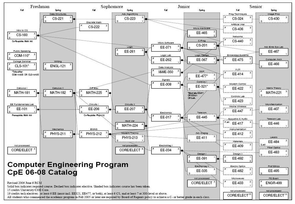
1 Course Overview Where does this course fit into the Electrical Engineering curriculum? Page 5 Course Overview Where does this course fit into the Computer Engineering curriculum? Page 6 3

2 Course Content What is this course? - In EE261 you learned: - basic combinational logic design - basic sequential logic design - In EE262 you learned: - how to implement logic circuits using off-the-shelf parts - EE367 is a follow-on course that looks at: - Large scale digital designs - Performance of digital circuitry - Programmable Logic Page 7 Course Content What does "Large" mean? - Large means that you can't do it by hand. We need a way to design and simulate Millions of gates - K-maps for a Pentium would take too much paper Page 8 4

3 Course Content We will learn VHDL in order to describe large digital designs - VHDL is a text based Hardware Description Language - We can simulate our digital designs created in VHDL Page 9 Course Content We can also prototype our designs using an FPGA - FPGA = Field Programmable Gate Array - An FPGA is a programmable logic device - In Lab, we will implement our designs and test them in FPGA hardware Page 10 5
4 Course Content What topics will be covered? 1) VHDL (Exam #1 Topics) 2) Medium Scale Combinational Logic Devices 3) More Complex Finite State Machines (Exam #2 Topics) 4) Computer Systems 5) FPGA Timing and Implementation Instead of a final, we will have a final project ex) - 4-bit microprocessor - peripheral controller (USB, Ethernet, RS232) - memory controller (EEprom, DDR, SRAM) Page 11 Combinational Logic Combinational Logic Gates : - Output depends on the logic value of the inputs - no storage Page 12 6
 = a+b AND out = a b f(a,b) = a b Page")
 = a+b NAND out = a b f(a,b) = a b Page")
5 NOT out = in = in f(in) = in = in OR out = a+b f(a,b) = a+b AND out = a b f(a,b) = a b Page 13 XOR out = a b f(a,b) = a b NOR out = a+b f(a,b) = a+b NAND out = a b f(a,b) = a b Page 14 7
6 XNOR out = a b f(a,b) = a b Also remember about XOR Gates: f(a,b) = a b = (a b + b a) Also remember the priority of logic operations (without parenthesis) is: NOT, AND, OR Page 15 DeMorgan s Theorems - Inverting the output of any gate results in the same function as the opposite gate (AND/OR) with inverted inputs Page 16 8
7 DeMorgan s Theorems - Graphically : breaking the bar changes the logic function (AND-OR) under the break out = a+b out = a+b out = a b 1) Break bar 2) Change + to under break Page 17 Boolean Expressions Using SOP - Logic functions can be described using a Sum of Products techniques - Sum of Products (SOP) is the summation of all minterms resulting in the truth table - A minterm is the expression for an input configuration which yields a TRUE output - A minterm expression is the AND ing of the input "1" signal configuration Truth Table a b out minterm m1 = a b 1 minterm m2 = a b SOP Expression : f(a,b) = a b + a b Note : un-minimized Boolean expression Page 18 9
8 Boolean Expressions Using POS - Logic functions can be described using a Product of Sums techniques - Product of Sums (POS) is the multiplication of all maxterms resulting in the truth table - A maxterm is the expression for an input configuration which yields a FALSE output - A maxterm expression is the OR ing of the input "0" signal configuration Truth Table a b out maxterm m0 = a+b (input configuration of 0's) maxterm m3 = a'+b' (input configuration of 0's) POS Expression : f(a,b) = (a+b) (a'+b') Page 19 Boolean Expressions Using SOP & POS - SOP and POS functions are equivalent SOP Expression : f(a,b) = a b + a b is equal to POS Expression : f(a,b) = (a+b) (a'+b') Page 20 10
9 Karnaugh Maps - K-maps provide a graphical method to find SOP/POS expressions - K-maps also provide a graphical method to perform logic minimization K-map SOP Process 1) Circle minterms to create SOP 2) Circle in Horizontal & Vertical manner 3) Circle in groups with powers of 2 (1,2,4,8, ) Truth Table a b out b 0 1 a 1 1 No dependency on b, No dependency on a, SOP expression : minterm = a minterm = b f(a,b) = a + b Page 21 Karnaugh Maps - K-maps provide a graphical method to find SOP/POS expressions - K-maps also provide a graphical method to perform logic minimization K-map POS Process 1) Circle maxterms to create SOP 2) Circle in Horizontal & Vertical manner 3) Circle in groups with powers of 2 (1,2,4,8, ) Truth Table a b out b 0 1 a 1 1 Dependency on a' and b', maxterm = a+b POS expression : f(a,b) = a + b Page 22 11
10 Sequential Logic - Concept of Storage Element - With Storage, logic functions can depend on current & past values of inputs - Sequential State Machines can be created D-Flip-Flop - on timing event (i.e., edge of clock input), D input goes to output CLK D D tc2q Page 23 State Machines - Moore : Outputs depend on present state - Mealy : Outputs depend on present state and current inputs Page 24 12
11 State Machine Example : Design a 2-bit Gray Code Counter ) Number of States? : 4 2) Number of bits to encode states? : 2 n =4, n=2 3) Moore or Mealy? : Moore For this counter, we can make the outputs be the state codes Page 25 State Machine Example : Design a 2-bit Gray Code Counter STATE Current Next Acur Bcur Anxt Bnxt Acur 0 1 Anxt Logic Bcur Anxt = Bcur Acur 0 1 A B Bnxt Logic Bcur Bnxt = Acur counter output CLK D A D B Page 26 13
CHAPTER 3 BASIC & COMBINATIONAL LOGIC CIRCUIT
 CHAPTER 3 BASIC & COMBINATIONAL LOGIC CIRCUIT CHAPTER CONTENTS 3.1 Introduction to Basic Gates 3.2 Analysing A Combinational Logic Circuit 3.3 Design A Combinational Logic Circuit From Boolean Expression
Chapter 3 Digital Logic Structures
 Chapter 3 Digital Logic Structures Transistor: Building Block of Computers Microprocessors contain millions of transistors Intel Pentium 4 (2): 48 million IBM PowerPC 75FX (22): 38 million IBM/Apple PowerPC
Number system: the system used to count discrete units is called number. Decimal system: the number system that contains 10 distinguished
 Number system: the system used to count discrete units is called number system Decimal system: the number system that contains 10 distinguished symbols that is 0-9 or digits is called decimal system. As
University of Technology
 University of Technology Lecturer: Dr. Sinan Majid Course Title: microprocessors 4 th year Lecture 7 & 8 NAND and XOR Implementations Combinational Design Procedure NAND-NAND & NOR-NOR Networks DeMorgan
Analysis procedure. To obtain the output Boolean functions from a logic diagram, proceed as follows:
 Combinational Logic Logic circuits for digital systems may be combinational or sequential. combinational circuit consists of input variables, logic gates, and output variables. 1 nalysis procedure To obtain
EECS 150 Homework 4 Solutions Fall 2008
 Problem 1: You have a 100 MHz clock, and need to generate 3 separate clocks at different frequencies: 20 MHz, 1kHz, and 1Hz. How many flip flops do you need to implement each clock if you use: a) a ring
(CSC-3501) Lecture 6 (31 Jan 2008) Seung-Jong Park (Jay) CSC S.J. Park. Announcement
 Lecture 6 (31 Jan 2008) Seung-Jong Park (Jay) CSC S.J. Park. Announcement") Seung-Jong Park (Jay) http://www.csc.lsu.edu/~sjpark Computer Architecture (CSC-3501) Lecture 6 (31 Jan 2008) 1 Announcement 2 1 Reminder A logic circuit is composed of: Inputs Outputs Functional specification
Seung-Jong Park (Jay) http://www.csc.lsu.edu/~sjpark Computer Architecture (CSC-3501) Lecture 6 (31 Jan 2008) 1 Announcement 2 1 Reminder A logic circuit is composed of: Inputs Outputs Functional specification
Asst. Prof. Thavatchai Tayjasanant, PhD. Power System Research Lab 12 th Floor, Building 4 Tel: (02)
") 2145230 Aircraft Electricity and Electronics Asst. Prof. Thavatchai Tayjasanant, PhD Email: taytaycu@gmail.com aycu@g a co Power System Research Lab 12 th Floor, Building 4 Tel: (02) 218-6527 1 Chapter
2145230 Aircraft Electricity and Electronics Asst. Prof. Thavatchai Tayjasanant, PhD Email: taytaycu@gmail.com aycu@g a co Power System Research Lab 12 th Floor, Building 4 Tel: (02) 218-6527 1 Chapter
Odd-Prime Number Detector The table of minterms is represented. Table 13.1
 Odd-Prime Number Detector The table of minterms is represented. Table 13.1 Minterm A B C D E 1 0 0 0 0 1 3 0 0 0 1 1 5 0 0 1 0 1 7 0 0 1 1 1 11 0 1 0 1 1 13 0 1 1 0 1 17 1 0 0 0 1 19 1 0 0 1 1 23 1 0 1
Digital Logic Circuits
 Digital Logic Circuits Let s look at the essential features of digital logic circuits, which are at the heart of digital computers. Learning Objectives Understand the concepts of analog and digital signals
Lecture 15 Analysis of Combinational Circuits
 Lecture 15 Analysis of Combinational Circuits Designing Combinational Logic Circuits A logic circuit having 3 inputs, A, B, C will have its output HIGH only when a majority of the inputs are HIGH. Step
Digital Electronic Concepts
 Western Technical College 10662137 Digital Electronic Concepts Course Outcome Summary Course Information Description Career Cluster Instructional Level Total Credits 4.00 Total Hours 108.00 This course
Name: Class: Date: 1. As more electronic systems have been designed using digital technology, devices have become smaller and less powerful.
 Name: Class: Date: DE Midterm Review 2 True/False Indicate whether the statement is true or false. 1. As more electronic systems have been designed using digital technology, devices have become smaller
CS302 Digital Logic Design Solved Objective Midterm Papers For Preparation of Midterm Exam
 CS302 Digital Logic Design Solved Objective Midterm Papers For Preparation of Midterm Exam MIDTERM EXAMINATION 2011 (October-November) Q-21 Draw function table of a half adder circuit? (2) Answer: - Page
Subject: Analog and Digital Electronics Code:15CS32
 Subject: Analog and Digital Electronics Code:15CS32 Syllabus: The Basic Gates : Review of Basic Logic gates, Positive and Negative Logic, Introduction to HDL. Combinational Logic Circuits:Sum-of-Products
Laboratory Manual CS (P) Digital Systems Lab
 Digital Systems Lab") Laboratory Manual CS 09 408 (P) Digital Systems Lab INDEX CYCLE I A. Familiarization of digital ICs and digital IC trainer kit 1 Verification of truth tables B. Study of combinational circuits 2. Verification
Laboratory Manual CS 09 408 (P) Digital Systems Lab INDEX CYCLE I A. Familiarization of digital ICs and digital IC trainer kit 1 Verification of truth tables B. Study of combinational circuits 2. Verification
ECE380 Digital Logic
 ECE38 Digital Logic Optimized Implementation of Logic Functions: Karnaugh Maps and Minimum Sum-of-Product Forms Dr. D. J. Jackson Lecture 7- Karnaugh map The key to finding a minimum cost SOP or POS form
Exam #2 EE 209: Fall 2017
 29 November 2017 Exam #2 EE 209: Fall 2017 Name: USCid: Session: Time: MW 10:30 11:50 / TH 11:00 12:20 (circle one) 1 hour 50 minutes Possible Score 1. 27 2. 28 3. 17 4. 16 5. 22 TOTAL 110 PERFECT 100
2 Logic Gates THE INVERTER. A logic gate is an electronic circuit which makes logic decisions. It has one output and one or more inputs.
 2 Logic Gates A logic gate is an electronic circuit which makes logic decisions. It has one output and one or more inputs. THE INVERTER The inverter (NOT circuit) performs the operation called inversion
Digital. Design. R. Ananda Natarajan B C D
 Digital E A B C D 0 1 2 3 4 5 6 Design 7 8 9 10 11 12 13 14 15 Y R. Ananda Natarajan Digital Design Digital Design R. ANANDA NATARAJAN Professor Department of Electronics and Instrumentation Engineering
Combinational Logic Design CH002
 Combinational Logic Design CH002 Figure 2.1 Circuit as a black box with inputs, outputs, and specifications Figure 2.2 Elements and nodes Figure 2.3 Combinational logic circuit Figure 2.4 Two OR implementations
Introduction to Digital Logic Missouri S&T University CPE 2210 Exam 1 Logistics
 Introduction to Digital Logic Missouri S&T University CPE 2210 Exam 1 Logistics Egemen K. Çetinkaya Egemen K. Çetinkaya Department of Electrical & Computer Engineering Missouri University of Science and
CS/ECE 252: INTRODUCTION TO COMPUTER ENGINEERING UNIVERSITY OF WISCONSIN MADISON
 CS/ECE 252: INTRODUCTION TO COMPUTER ENGINEERING UNIVERSITY OF WISCONSIN MADISON Instructor: Andy Phelps TAs: Newsha Ardalani, Peter Ohmann, and Jai Menon Midterm Examination 2 In Class (50 minutes) Wednesday,
Dr. Nicola Nicolici COE/EE2DI4 Midterm Test #1 Oct 18, 2006
 COE/EE2DI4 Midterm Test #1 Fall 2006 Page 1 Dr. Nicola Nicolici COE/EE2DI4 Midterm Test #1 Oct 18, 2006 Instructions: This examination paper includes 10 pages and 20 multiple-choice questions starting
Department of Electronics and Communication Engineering
 Department of Electronics and Communication Engineering Sub Code/Name: BEC3L2- DIGITAL ELECTRONICS LAB Name Reg No Branch Year & Semester : : : : LIST OF EXPERIMENTS Sl No Experiments Page No Study of
ECE 172 Digital Systems. Chapter 2 Digital Hardware. Herbert G. Mayer, PSU Status 6/30/2018
 ECE 172 Digital Systems Chapter 2 Digital Hardware Herbert G. Mayer, PSU Status 6/30/2018 1 Syllabus l Term Sharing l Standard Forms l Hazards l Decoders l PLA vs. PAL l PROM l Bibliography 2 Product Term
Logic diagram: a graphical representation of a circuit
 LOGIC AND GATES Introduction to Logic (1) Logic diagram: a graphical representation of a circuit Each type of gate is represented by a specific graphical symbol Truth table: defines the function of a gate
Gates and Circuits 1
 1 Gates and Circuits Chapter Goals Identify the basic gates and describe the behavior of each Describe how gates are implemented using transistors Combine basic gates into circuits Describe the behavior
Digital Electronics Course Objectives
 Digital Electronics Course Objectives In this course, we learning is reported using Standards Referenced Reporting (SRR). SRR seeks to provide students with grades that are consistent, are accurate, and
Logic Symbols with Truth Tables INVERTER A B NAND A B C NOR C A B A B C XNOR A B C A B Digital Logic 1
 Slide Logic Symbols with Truth Tables UFFER INVERTER ND NND OR NOR XOR XNOR 6.7 Digital Logic Digital logic can be described in terms of standard logic symbols and their corresponding truth tables. The
Logic Design I (17.341) Fall Lecture Outline
 Fall Lecture Outline") Logic Design I (17.341) Fall 2011 Lecture Outline Class # 07 October 31, 2011 / November 07, 2011 Dohn Bowden 1 Today s Lecture Administrative Main Logic Topic Homework 2 Course Admin 3 Administrative
Logic Design I (17.341) Fall 2011 Lecture Outline Class # 07 October 31, 2011 / November 07, 2011 Dohn Bowden 1 Today s Lecture Administrative Main Logic Topic Homework 2 Course Admin 3 Administrative
Digital Fundamentals
 Digital Fundamentals Tenth Edition Floyd hapter 5 Floyd, Digital Fundamentals, th ed 28 Pearson Education 29 Pearson Education, Upper Saddle River, NJ 7458. ll Rights Reserved ombinational Logic ircuits
Function Table of an Odd-Parity Generator Circuit
 Implementation of an Odd-Parity Generator Circuit The first step in implementing any circuit is to represent its operation in terms of a Truth or Function table. The function table for an 8-bit data as
Chapter 3 Digital Logic Structures
 Chapter 3 Digital Logic Structures Transistor: Building Block of Computers Microprocessors contain millions of transistors Intel Pentium 4 (2000): 48 million IBM PowerPC 750FX (2002): 38 million IBM/Apple
Chapter 3 Describing Logic Circuits Dr. Xu
 Chapter 3 Describing Logic Circuits Dr. Xu Chapter 3 Objectives Selected areas covered in this chapter: Operation of truth tables for AND, NAND, OR, and NOR gates, and the NOT (INVERTER) circuit. Boolean
CS302 - Digital Logic Design Glossary By
 CS302 - Digital Logic Design Glossary By ABEL : Advanced Boolean Expression Language; a software compiler language for SPLD programming; a type of hardware description language (HDL) Adder : A digital
DIGITAL ELECTRONICS. Methods & diagrams : 1 Graph plotting : - Tables & analysis : - Questions & discussion : 6 Performance : 3
 DIGITAL ELECTRONICS Marking scheme : Methods & diagrams : 1 Graph plotting : - Tables & analysis : - Questions & discussion : 6 Performance : 3 Aim: This experiment will investigate the function of the
COURSE LEARNING OUTCOMES AND OBJECTIVES
 COURSE LEARNING OUTCOMES AND OBJECTIVES A student who successfully fulfills the course requirements will have demonstrated: 1. an ability to analyze and design CMOS logic gates 1-1. convert numbers from
Written exam IE1204/5 Digital Design Friday 13/
 Written exam IE204/5 Digital Design Friday 3/ 207 08.00-2.00 General Information Examiner: Ingo Sander. Teacher: Kista, William Sandqvist tel 08-7904487 Teacher: Valhallavägen, Ahmed Hemani 08-7904469
COMPUTER ORGANIZATION & ARCHITECTURE DIGITAL LOGIC CSCD211- DEPARTMENT OF COMPUTER SCIENCE, UNIVERSITY OF GHANA
 COMPUTER ORGANIZATION & ARCHITECTURE DIGITAL LOGIC LOGIC Logic is a branch of math that tries to look at problems in terms of being either true or false. It will use a set of statements to derive new true
ELECTRONIC CIRCUITS. Time: Three Hours Maximum Marks: 100
 EC 40 MODEL TEST PAPER - 1 ELECTRONIC CIRCUITS Time: Three Hours Maximum Marks: 100 Answer five questions, taking ANY TWO from Group A, any two from Group B and all from Group C. All parts of a question
Chapter 4 Combinational Logic Circuits
 Chapter 4 Combinational Logic Circuits Chapter 4 Objectives Selected areas covered in this chapter: Converting logic expressions to sum-of-products expressions. Boolean algebra and the Karnaugh map as
JEFFERSON COLLEGE COURSE SYLLABUS ETC255 INTRODUCTION TO DIGITAL CIRCUITS. 6 Credit Hours. Prepared by: Dennis Eimer
 JEFFERSON COLLEGE COURSE SYLLABUS ETC255 INTRODUCTION TO DIGITAL CIRCUITS 6 Credit Hours Prepared by: Dennis Eimer Revised Date: August, 2007 By Dennis Eimer Division of Technology Dr. John Keck, Dean
Module 4: Design and Analysis of Combinational Circuits 1. Module-4. Design and Analysis of Combinational Circuits
 1 Module-4 Design and Analysis of Combinational Circuits 4.1 Motivation: This topic develops the fundamental understanding and design of adder, substractor, code converter multiplexer, demultiplexer etc
QUIZ. What do these bits represent?
 QUIZ What do these bits represent? 1001 0110 1 QUIZ What do these bits represent? Unsigned integer: 1101 1110 Signed integer (2 s complement): Fraction: IBM 437 character: Latin-1 character: Huffman-compressed
FPGA Based System Design
 FPGA Based System Design Reference Wayne Wolf, FPGA-Based System Design Pearson Education, 2004 Why VLSI? Integration improves the design: higher speed; lower power; physically smaller. Integration reduces
Finite State Machines CS 64: Computer Organization and Design Logic Lecture #16
 Finite State Machines CS 64: Computer Organization and Design Logic Lecture #16 Ziad Matni Dept. of Computer Science, UCSB Lecture Outline Review of Latches vs. FFs Finite State Machines Moore vs. Mealy
6.1 In this section, you will design (but NOT build) a circuit with 4 inputs,
 a circuit with 4 inputs,") EE 2449 Experiment 6 Jack Levine and Nancy Warter-Perez //208 CALIFORNIA STATE UNIVERSITY LOS ANGELES Department of Electrical and Computer Engineering EE-2449 Digital Logic Lab EXPERIMENT 6 COMBINATIONAL
EE 2449 Experiment 6 Jack Levine and Nancy Warter-Perez //208 CALIFORNIA STATE UNIVERSITY LOS ANGELES Department of Electrical and Computer Engineering EE-2449 Digital Logic Lab EXPERIMENT 6 COMBINATIONAL
Digital Electronics. A. I can list five basic safety rules for electronics. B. I can properly display large and small numbers in proper notation,
 St. Michael Albertville High School Teacher: Scott Danielson September 2016 Content Skills Learning Targets Standards Assessment Resources & Technology CEQ: WHAT MAKES DIGITAL ELECTRONICS SO IMPORTANT
B.C.A 2017 DIGITAL ELECTRONICS BCA104T MODULE SPECIFICATION SHEET. Course Outline
 Course Outline B.C.A 2017 DIGITAL ELECTRONICS BCA104T MODULE SPECIFICATION SHEET The purpose of the course is to teach principles of digital electronics. This course covers varieties of topics including
ECE380 Digital Logic
 ECE380 Digital Logic Implementation Technology: Standard Chips and Programmable Logic Devices Dr. D. J. Jackson Lecture 10-1 Standard chips A number of chips, each with a few logic gates, are commonly
EEE 301 Digital Electronics
 EEE 301 Digital Electronics Lecture 1 Course Contents Introduction to number systems and codes. Analysis and synthesis of digital logic circuits: Basic logic functions, Boolean algebra,combinational logic
Digital Systems Principles and Applications TWELFTH EDITION. 3-3 OR Operation With OR Gates. 3-4 AND Operations with AND gates
 Digital Systems Principles and Applications TWELFTH EDITION CHAPTER 3 Describing Logic Circuits Part -2 J. Bernardini 3-3 OR Operation With OR Gates An OR gate is a circuit with two or more inputs, whose
Course Outline Cover Page
 College of Micronesia FSM P.O. Box 159 Kolonia, Pohnpei Course Outline Cover Page Digital Electronics I VEE 135 Course Title Department and Number Course Description: This course provides the students
EMT1250 LABORATORY EXPERIMENT. EXPERIMENT # 4: Combinational Logic Circuits. Name: Date:
 EXPERIMENT # 4: Combinational Logic Circuits Name: Date: Equipment/Parts Needed: 5V DC Power Supply Digital Trainer (Logic Probe) Breadboard DIP Switch 7400 NAND gate 7402 NOR gate 7404 Inverter 7408 AND
Chapter 4 Combinational Logic Circuits
 Chapter 4 Combinational Logic Circuits Chapter 4 Objectives Selected areas covered in this chapter: Converting logic expressions to sum-of-products expressions. Boolean algebra and the Karnaugh map as
LOGIC GATES AND LOGIC CIRCUITS A logic gate is an elementary building block of a Digital Circuit. Most logic gates have two inputs and one output.
 LOGIC GATES AND LOGIC CIRCUITS A logic gate is an elementary building block of a Digital Circuit. Most logic gates have two inputs and one output. At any given moment, every terminal is in one of the two
SYNTHESIS OF COMBINATIONAL CIRCUITS
 HPTER 6 SYNTHESIS O OMINTIONL IRUITS 6.1 Introduction oolean functions can be expressed in the forms of sum-of-products and productof-sums. These expressions can also be minimized using algebraic manipulations
Chapter 1: Digital logic
 Chapter 1: Digital logic I. Overview In PHYS 252, you learned the essentials of circuit analysis, including the concepts of impedance, amplification, feedback and frequency analysis. Most of the circuits
Lecture 3: Logic circuit. Combinational circuit and sequential circuit
 Lecture 3: Logic circuit Combinational circuit and sequential circuit TRAN THI HONG HONG@IS.NAIST.JP Content Lecture : Computer organization and performance evaluation metrics Lecture 2: Processor architecture
LOGIC DIAGRAM: HALF ADDER TRUTH TABLE: A B CARRY SUM. 2012/ODD/III/ECE/DE/LM Page No. 1
 LOGIC DIAGRAM: HALF ADDER TRUTH TABLE: A B CARRY SUM K-Map for SUM: K-Map for CARRY: SUM = A B + AB CARRY = AB 22/ODD/III/ECE/DE/LM Page No. EXPT NO: DATE : DESIGN OF ADDER AND SUBTRACTOR AIM: To design
Unit level 4 Credit value 15. Introduction. Learning Outcomes
 Unit 20: Unit code Digital Principles T/615/1494 Unit level 4 Credit value 15 Introduction While the broad field of electronics covers many aspects, it is digital electronics which now has the greatest
Electronic Components And Circuit Analysis
 Theory /Practical Theory Semester /Annual Semester Semester No. I II Swami Ramanand Teerth Marathwada University, Nanded Syllabus B. Sc. First Year ELECTRONICS Semester System (MCQ Pattern) (To Be Implemented
NUMBER SYSTEM AND CODES
 NUMBER SYSTEM AND CODES INTRODUCTION:- The term digital refers to a process that is achieved by using discrete unit. In number system there are different symbols and each symbol has an absolute value and
Combinational Circuits: Multiplexers, Decoders, Programmable Logic Devices
 Combinational Circuits: Multiplexers, Decoders, Programmable Logic Devices Lecture 5 Doru Todinca Textbook This chapter is based on the book [RothKinney]: Charles H. Roth, Larry L. Kinney, Fundamentals
EE 280 Introduction to Digital Logic Design
 EE 280 Introduction to Digital Logic Design Lecture 1. Introduction EE280 Lecture 1 1-1 Instructors: EE 280 Introduction to Digital Logic Design Dr. Lukasz Kurgan (section A1) office: ECERF 6 th floor,
SRV ENGINEERING COLLEGE SEMBODAI RUKMANI VARATHARAJAN ENGINEERING COLLEGE SEMBODAI
 SEMBODAI RUKMANI VARATHARAJAN ENGINEERING COLLEGE SEMBODAI 6489 (Approved By AICTE,Newdelhi Affiliated To ANNA UNIVERSITY::Chennai) CS 62 DIGITAL ELECTRONICS LAB (REGULATION-23) LAB MANUAL DEPARTMENT OF
ECE 241 Digital Systems. Basic Information
 ECE 241 Digital Systems Fall 2013 J. Anderson, P. Chow, K. Truong, B. Wang Basic Information Instructors and Lecture Information Section 1 2 3 4 Instructor Jason Anderson Kevin Truong Paul Chow Belinda
The book has excellent descrip/ons of this topic. Please read the book before watching this lecture. The reading assignment is on the website.
 5//22 Digital Logic Design Introduc/on to Computer Architecture David Black- Schaffer Contents 2 Combina3onal logic Gates Logic Truth tables Truth tables Gates (Karnaugh maps) Common components: Mul/plexors,
UNIT-2: BOOLEAN EXPRESSIONS AND COMBINATIONAL LOGIC CIRCUITS
 UNIT-2: BOOLEAN EXPRESSIONS AND COMBINATIONAL LOGIC CIRCUITS STRUCTURE 2. Objectives 2. Introduction 2.2 Simplification of Boolean Expressions 2.2. Sum of Products 2.2.2 Product of Sums 2.2.3 Canonical
LIST OF EXPERIMENTS. KCTCET/ /Odd/3rd/ETE/CSE/LM
 LIST OF EXPERIMENTS. Study of logic gates. 2. Design and implementation of adders and subtractors using logic gates. 3. Design and implementation of code converters using logic gates. 4. Design and implementation
3.1 There are three basic logic functions from which all circuits can be designed: NOT (invert), OR, and
, OR, and") EE 2449 Experiment 3 Jack Levine and Nancy Warter-Perez, Revised 6/12/17 CALIFORNIA STATE UNIVERSITY LOS ANGELES Department of Electrical and Computer Engineering EE-2449 Digital Logic Lab EXPERIMENT 3
EE 2449 Experiment 3 Jack Levine and Nancy Warter-Perez, Revised 6/12/17 CALIFORNIA STATE UNIVERSITY LOS ANGELES Department of Electrical and Computer Engineering EE-2449 Digital Logic Lab EXPERIMENT 3
1.) If a 3 input NOR gate has eight input possibilities, how many of those possibilities result in a HIGH output? (a.) 1 (b.) 2 (c.) 3 (d.) 7 (e.
 If a 3 input NOR gate has eight input possibilities, how many of those possibilities result in a HIGH output? (a.) 1 (b.) 2 (c.) 3 (d.) 7 (e.") Name: Multiple Choice 1.) If a 3 input NOR gate has eight input possibilities, how many of those possibilities result in a HIGH output? (a.) 1 (b.) 2 (c.) 3 (d.) 7 (e.) 8 2.) The output of an OR gate with
Name: Multiple Choice 1.) If a 3 input NOR gate has eight input possibilities, how many of those possibilities result in a HIGH output? (a.) 1 (b.) 2 (c.) 3 (d.) 7 (e.) 8 2.) The output of an OR gate with
Combinational Logic. Combinational Logic Design Process, Three State Buffers, Decoders, Multiplexers, Encoders, Demultiplexers, Other Considerations
 Combinational Logic Combinational Logic Design Process, Three State Buffers, Decoders, Multiplexers, Encoders, Demultiplexers, Other Considerations Copyright (c) 2012 Sean Key Combinational Logic Design
Chapter 4: FLIP FLOPS. (Sequential Circuits) By: Siti Sabariah Hj. Salihin ELECTRICAL ENGINEERING DEPARTMENT EE 202 : DIGITAL ELECTRONICS 1
 By: Siti Sabariah Hj. Salihin ELECTRICAL ENGINEERING DEPARTMENT EE 202 : DIGITAL ELECTRONICS 1") Chapter 4: FLIP FLOPS (Sequential Circuits) By: Siti Sabariah Hj. Salihin ELECTRICAL ENGINEERING DEPARTMENT 1 CHAPTER 4 : FLIP FLOPS Programme Learning Outcomes, PLO Upon completion of the programme, graduates
Chapter 4: FLIP FLOPS (Sequential Circuits) By: Siti Sabariah Hj. Salihin ELECTRICAL ENGINEERING DEPARTMENT 1 CHAPTER 4 : FLIP FLOPS Programme Learning Outcomes, PLO Upon completion of the programme, graduates
Field Programmable Gate Array
 9 Field Programmable Gate Array This chapter introduces the principles, implementation and programming of configurable logic circuits, from the point of view of cell design and interconnection strategy.
Objective Questions. (a) Light (b) Temperature (c) Sound (d) all of these
 Light (b) Temperature (c) Sound (d) all of these") Objective Questions Module 1: Introduction 1. Which of the following is an analog quantity? (a) Light (b) Temperature (c) Sound (d) all of these 2. Which of the following is a digital quantity? (a) Electrical
Objective Questions Module 1: Introduction 1. Which of the following is an analog quantity? (a) Light (b) Temperature (c) Sound (d) all of these 2. Which of the following is a digital quantity? (a) Electrical
Hashemite University Mechatronics Engineering Department Logic and Electronics Laboratory Manual
 Hashemite University Mechatronics Engineering Department Logic and Electronics Laboratory Manual The Hashemite University Faculty of Engineering Department of Mechatronics Engineering Logic and Electronics
Project Board Game Counter: Digital
 Project 1.3.3 Board Game Counter: Digital Introduction Just a few short weeks ago, most of you knew little or nothing about digital electronics. Now you are about to build and simulate a complete design.
1. The decimal number 62 is represented in hexadecimal (base 16) and binary (base 2) respectively as
 and binary (base 2) respectively as") BioE 1310 - Review 5 - Digital 1/16/2017 Instructions: On the Answer Sheet, enter your 2-digit ID number (with a leading 0 if needed) in the boxes of the ID section. Fill in the corresponding numbered
BioE 1310 - Review 5 - Digital 1/16/2017 Instructions: On the Answer Sheet, enter your 2-digit ID number (with a leading 0 if needed) in the boxes of the ID section. Fill in the corresponding numbered
Introduction. BME208 Logic Circuits Yalçın İŞLER
 Introduction BME208 Logic Circuits Yalçın İŞLER islerya@yahoo.com http://me.islerya.com 1 Lecture Three hours a week (three credits) No other sections, please register this section Tuesday: 09:30 12:15
Learning Outcomes. Spiral 2 3. DeMorgan Equivalents NEGATIVE (ACTIVE LO) LOGIC. Negative Logic One hot State Assignment System Design Examples
 LOGIC. Negative Logic One hot State Assignment System Design Examples") 2-3. Learning Outcomes 2-3.2 Spiral 2 3 Negative Logic One hot State Assignment System Design Examples I understand the active low signal convention and how to interface circuits that use both active high
2-3. Learning Outcomes 2-3.2 Spiral 2 3 Negative Logic One hot State Assignment System Design Examples I understand the active low signal convention and how to interface circuits that use both active high
Chapter 2 Introduction to Logic Circuits
 Chapter 2 Introduction to Logic Circuits Logic unctions and circuits Boolean algebra Snthesis o digital circuits Introduction to CAD tools Introduction to VHDL Logic unctions and Circuits and 2 are binar
IES Digital Mock Test
 . The circuit given below work as IES Digital Mock Test - 4 Logic A B C x y z (a) Binary to Gray code converter (c) Binary to ECESS- converter (b) Gray code to Binary converter (d) ECESS- To Gray code
Topics. Memory Reliability and Yield Control Logic. John A. Chandy Dept. of Electrical and Computer Engineering University of Connecticut
 Topics Memory Reliability and Yield Control Logic Reliability and Yield Noise Sources in T DRam BL substrate Adjacent BL C WBL α-particles WL leakage C S electrode C cross Transposed-Bitline Architecture
ENG 100 Electric Circuits and Systems Lab 6: Introduction to Logic Circuits
 ENG 100 Electric Circuits and Systems Lab 6: Introduction to Logic Circuits Professor P. Hurst Lecture 5:10p 6:00p TR, Kleiber Hall Lab 2:10p 5:00p F, 2161 Kemper Hall LM741 Operational Amplifier Courtesy
Digital Applications (CETT 1415) Credit: 4 semester credit hours (3 hours lecture, 4 hours lab) Prerequisite: CETT 1403 & CETT 1405
 Credit: 4 semester credit hours (3 hours lecture, 4 hours lab) Prerequisite: CETT 1403 & CETT 1405") Digital Applications () Credit: 4 semester credit hours (3 hours lecture, 4 hours lab) Prerequisite: CETT 1403 & CETT 1405 Course Description This course covers digital techniques and numbering systems,
Digital Applications () Credit: 4 semester credit hours (3 hours lecture, 4 hours lab) Prerequisite: CETT 1403 & CETT 1405 Course Description This course covers digital techniques and numbering systems,
S-[F] NPW-02 June All Syllabus B.Sc. [Electronics] Ist Year Semester-I & II.doc - 1 -
![S-[F] NPW-02 June All Syllabus B.Sc. [Electronics] Ist Year Semester-I & II.doc - 1 -](/thumbs/79/79759849.jpg "S-[F] NPW-02 June All Syllabus B.Sc. [Electronics] Ist Year Semester-I & II.doc - 1 -") - 1 - - 2 - - 3 - DR. BABASAHEB AMBEDKAR MARATHWADA UNIVERSITY, AURANGABAD SYLLABUS of B.Sc. FIRST & SECOND SEMESTER [ELECTRONICS (OPTIONAL)] {Effective from June- 2013 onwards} - 4 - B.Sc. Electronics
- 1 - - 2 - - 3 - DR. BABASAHEB AMBEDKAR MARATHWADA UNIVERSITY, AURANGABAD SYLLABUS of B.Sc. FIRST & SECOND SEMESTER [ELECTRONICS (OPTIONAL)] {Effective from June- 2013 onwards} - 4 - B.Sc. Electronics
Unit 1 Foundations in Electronics - Lesson 1.1 Introduction to Electronics Standards Essential Question Enduring Understandings
 Course: DIGITAL ELECTRONICS- PROJECT LEAD THE WAY (DE-PLTW) Year: 2017-2018 Teacher: Mr. Christopher Reynolds/ Mr. Kenneth Rice Unit 1 Foundations in Electronics - Lesson 1.1 Introduction to Electronics
Formal Foundation of Digital Design
 Chapter 2: Switching Algebra and Logic Circuits 78 22 Digital Logic Design @ Department of Computer Engineering KKU. Formal Foundation of Digital Design In 854 George Boole published An investigation into
In this lecture: Lecture 8: ROM & Programmable Logic Devices
 In this lecture: Lecture 8: ROM Programmable Logic Devices Dr Pete Sedcole Department of EE Engineering Imperial College London http://caseeicacuk/~nps/ (Floyd, 3 5, 3) (Tocci 2, 24, 25, 27, 28, 3 34)
Electronics. Digital Electronics
 Electronics Digital Electronics Introduction Unlike a linear, or analogue circuit which contains signals that are constantly changing from one value to another, such as amplitude or frequency, digital
Digital Design and System Implementation. Overview of Physical Implementations
 Digital Design and System Implementation Overview of Physical Implementations CMOS devices CMOS transistor circuit functional behavior Basic logic gates Transmission gates Tri-state buffers Flip-flops
Scheme & Syllabus. New. B.Sc. Electronics. (Pass /Maintenance) Course. I st to IV th Semester. w.e.f. July Devi Ahilya Vishwavidyalaya,
 Course. I st to IV th Semester. w.e.f. July Devi Ahilya Vishwavidyalaya,") Scheme & Syllabus of New B.Sc. Electronics (Pass /Maintenance) Course I st to IV th Semester w.e.f. July 2011 Devi Ahilya Vishwavidyalaya, Indore (M.P.) 452001 SEMESTER SYSTEM, 2011-2014 PROPOSED SCHEME
Scheme & Syllabus of New B.Sc. Electronics (Pass /Maintenance) Course I st to IV th Semester w.e.f. July 2011 Devi Ahilya Vishwavidyalaya, Indore (M.P.) 452001 SEMESTER SYSTEM, 2011-2014 PROPOSED SCHEME
EECS150 - Digital Design Lecture 2 - CMOS
 EECS150 - Digital Design Lecture 2 - CMOS August 29, 2002 John Wawrzynek Fall 2002 EECS150 - Lec02-CMOS Page 1 Outline Overview of Physical Implementations CMOS devices Announcements/Break CMOS transistor
Paper No. Name of the Paper Theory marks Practical marks Periods per week Semester-I I Semiconductor
 Swami Ramanand Teerth Marathwada University, Nanded B. Sc. First Year Electronics Syllabus Semester system (To be implemented from Academic Year 2009-10) Name of the Theory marks Practical marks Periods
EE 42/100 Lecture 24: Latches and Flip Flops. Rev B 4/21/2010 (2:04 PM) Prof. Ali M. Niknejad
 Prof. Ali M. Niknejad") A. M. Niknejad University of California, Berkeley EE 100 / 42 Lecture 24 p. 1/21 EE 42/100 Lecture 24: Latches and Flip Flops ELECTRONICS Rev B 4/21/2010 (2:04 PM) Prof. Ali M. Niknejad University of California,
A. M. Niknejad University of California, Berkeley EE 100 / 42 Lecture 24 p. 1/21 EE 42/100 Lecture 24: Latches and Flip Flops ELECTRONICS Rev B 4/21/2010 (2:04 PM) Prof. Ali M. Niknejad University of California,
UC Berkeley CS61C : Machine Structures
 CS61C L22 Representations of Combinatorial Logic Circuits (1) inst.eecs.berkeley.edu/~cs61c UC Berkeley CS61C : Machine Structures Lecture 22 Representations of Combinatorial Logic Circuits 27-3-9 TA David
Lecture 02: Digital Logic Review
 CENG 3420 Lecture 02: Digital Logic Review Bei Yu byu@cse.cuhk.edu.hk CENG3420 L02 Digital Logic. 1 Spring 2017 Review: Major Components of a Computer CENG3420 L02 Digital Logic. 2 Spring 2017 Review:
Gates and and Circuits
 Chapter 4 Gates and Circuits Chapter Goals Identify the basic gates and describe the behavior of each Describe how gates are implemented using transistors Combine basic gates into circuits Describe the