Electronics. Digital Electronics
|
|
|
- Alaina Bradford
- 6 years ago
- Views:
Transcription
1 Electronics Digital Electronics
2 Introduction Unlike a linear, or analogue circuit which contains signals that are constantly changing from one value to another, such as amplitude or frequency, digital circuits process signals that contain just two voltage levels or states, labelled logic "0" and logic "1". The voltages used to represent a digital circuit are called "logic levels". Generally, a logic "1" represents a higher voltage, which is referred to as a HIGH and a logic "0" is referred to as a LOW

3 Analogue Circuits Electronic circuits can be divided into two main categories. Analogue Circuits - Analogue or Linear circuits amplify or respond to continuously varying voltage levels over a period of time. The output from the potentiometer varies as the wiper terminal is rotated producing an infinite number of voltage points between 0 volts and V max. As the voltage output varies either slowly or rapidly there is no sudden change between two voltage levels giving a continuous output voltage. Examples of analogue signals include temperature, pressure, liquid levels and light intensity

4 Digital Circuits Digital Circuits - Digital circuits produce or respond too two distinct voltage levels representing either a Logic level "1" or a Logic level "0". As the wheel rotates, the optoswitch will generate an output that changes quickly beetween two discrete voltage levels. For example, 5V volts to 0 volt but NOT 2.5V, 3.1V or 4.6V. Then the major difference between an analogue signal or quantity and a digital quantity is that an "Analogue" quantity is continuously changing over time while a "Digital" quantity has discrete (step by step) values. LOW to HIGH or HIGH to LOW

5 Voltage Levels In all electronic circuits, only two logic levels are allowed and these levels are referred to as "logic 1 or logic 0", "high or low", "true or false". Most logic systems use positive logic, in which a logic "0" is represented by zero volts and a logic "1" is represented by a higher voltage, such as +5 volts. In standard TTL (transistor-transistor-logic) IC's there is a defined range of input and output voltage limits for defining what is a logic "1" value and what is a logic "0" value.

6 Noise Noise is the name given to a random and unwanted voltage that is induced into electronic circuits by external interference, such as from nearby switches, power supply fluctuations or from wires and other conductors that pick-up stray electromagnetic radiation. However, between these defined HIGH and LOW values lies what is generally called a "no-man's land" (the blue area's above) and if we apply a signal voltage of a value within this no-man's land area we do not know whether the logic gate will respond to it as a level "0" or as a level "1", and the output will become unpredictable.
7 Decimal to Binary Conversion The Decimal or "denary" counting system uses the Base of 10 numbering system where each digit in a number takes on one of ten possible values from 0 to 9, eg 213 (Two Hundred and Thirteen). In a decimal system each digit has a value ten times greater than its previous number and this decimal numbering system. In the decimal or denary system, the columns have values of units, tens, hundreds etc as we move from right to left and mathematically these values are written as 10 0, 10 1, 10 2, 10 3 etc (6 103) + (1 102) + (6 101) + (3 100) = 6163
8 Decimal to Binary Conversion Unlike the decimal numbering system which uses the base of 10, digital logic uses just two values or states, a logic level "1" or a logic level "0", so each "0" and "1" is considered to be a single digit in a Base of 2 orbinary numbering system. In the binary numbering system, each digit has a value twice that of the previous digit but can only have a value of either "1" or " Decimal Digit Value Binary Digit Value Then, the binary array of digits is equivalent to in decimal or denary.
9 Decimal to Binary Conversion Another method of converting Decimal to Binary number equivalents is to write down the decimal number and to continually divide by 2 (two) to give a result and a remainder of either a "1" or a "0" until the final result equals zero. Convert 83 to binary 83:2=41 remainder 1 LSB 41:2=20 remainder 1 20:2=10 remainder 0 10:2=5 remainder 0 5:2=2 reaminder 1 2:2=1 remainder 0 1:2=0 remainder 1 MSB =
10 Binary Numbers Binary numbers can be added together and subtracted just like decimal numbers with the result being combined into one of several size ranges depending upon the number of bits being used. The classification of individual bits into larger groups are generally referred to by the following more common names Number of Binary Digits (bits) Common Name 1 Bit 4 Nibble 8 Byte 16 Word 32 Double Word 64 Quad Word
11 Binary Numbers As micro-controller or microprocessor systems become increasingly larger, the individual binary digits (bits) are now grouped together into 8 s to form a single BYTE with most computer hardware such as hard drives and memory modules commonly indicate their size in Megabytes or even Gigabytes. Number of Bytes Common Name 1,024 (2 10 ) kilobyte (kb) 1,048,576 (2 20 ) Megabyte (Mb) 1,073,741,824 (2 30 ) Gigabyte (Gb) a very long number! (2 40 ) Terabyte (Tb)
12 Binary based other number systems The one main disadvantage of Binary Numbers is that the binary equivalent of a large decimal number can be quite long, which makes it difficult to both read or write without producing errors especially when working with 16 or 32-bit numbers. One common way of overcoming this problem is to arrange the binary numbers into groups Base, b Byte (8-bits) Word (16-bits) Decimal 0 to to 65, Binary to to Hexadecimal 00 to FF to FFFF 16 Octal 000 to to the memory of a computer would use hexadecimal numbers while the keyboard uses decimal numbers
13 Hexadecimal (16) the Hexadecimal numbering system uses only four digits to express a single 16-bit word length, and as a result it is the most commonly used Binary Numbering System for electronic and micro-electronic system Decimal 4-bit Binary Hexadecimal Decimal 4-bit Binary Hexadecimal A B C D E F (1+0) (1+1) Continuing upwards in groups of four
14 Counting: Using Hexadecimal Numbers 0...to...9, A,B,C,D,E,F, 10...to...19, 1A, 1B, 1C, 1D, 1E, 1F, 20, 21 Writing in binary form: 20F 16 =( ) 2 Conversions 3A 16 = ( ) 2 =0*128+0*64+1*32+1*16+1*8+0*4+1*2+0*1=58 3A 16 =3*16+10*1=58 20F 16 =2*256+0*16+15=527
15 Boolean (or Switching) Algebra Besides basic arithemtical operations, the binary numbers, which are inherently represents true or false logic states, are also used in logical operations. Boolean (or Switching) Algebra deals mainly with the theory that both logic and set operations are either "TRUE" or "FALSE" but not both at the same time. For example, A + A = A and not 2A as it would be in normal algebra. Boolean algebra is a simple and effective way of representing the switching action of standard Logic Gates and the basic logic statements.
16 The logic AND Function The Logic AND Function function states that two or more events must occur together and at the same time for an output action to occur. But the order at which they occur is unimportant as it does not affect the final result
17 The logic AND Function Switch A Switch B Output Description A and B are both open, lamp OFF A is open and B is closed, lamp OFF A is closed and B is open, lamp OFF A is closed and B is closed, lamp ON Boolean Expression (A AND B) A. B

18 TTL Logic Circuit The logic AND Gate TTL Logic Types 74LS08 Quad 2-input 74LS11 Triple 3-input 74LS21 Dual 4-input CMOS Logic Types CD4081 Quad 2-input CD4073 Triple 3-input CD4082 Dual 4-input
19 The Logic OR Function The Logic OR Function function states that an output action will occur or become TRUE if either one "OR" more events are TRUE, but the order at which they occur is unimportant as it does not affect the final result.
20 The Logic OR Function Switch A Switch B Output Description A is open and B is open, lamp OFF A is open and B is closed, lamp ON A is closed and B is open, lamp ON A is closed and B is closed, lamp ON Boolean Expression (A OR B) A + B

21 TTL Logic Circuit The logic OR Gate TTL Logic Types 74LS32 Quad 2-input CMOS Logic Types CD4071 Quad 2-input CD4075 Triple 3-input CD4072 Dual 4-input
22 The Logic XOR Function The Logic XOR Function function states that an output action will occur or become TRUE if and only if one "OR" event is TRUE. It excludes the state in which both OR events are true. XOR means "one or the other but not both". It represents the inequality function. The output is HIGH (1) if the inputs are not alike otherwise the output is LOW (0). Symbol Boolean Expression Q = A B Truth Table A B Q
23 The Logic NOT Function The Logic NOT Function is simply a single input inverter that changes the input of a logic level "1" to an output of logic level "0" and vice versa. They are more commonly known as Inverters because they invert the signal The logic NOT function is so called because its output state is NOT the same as its input state. It is generally denoted by a bar or overline ( ) over its input symbol which denotes the inversion operation.


24 The Logic NOT Function Switch 1 0 Boolean Expression Output 0 1 A
25 The NAND or Not AND function The NAND or Not AND function is a combination of the two separate logical functions, the AND function and the NOT function connected together in series. Switch A Switch B Output Description A and B are both open, lamp ON A is open and B is closed, lamp ON A is closed and B is open, lamp ON A is closed and B is closed, lamp OFF Boolean Expression (A AND B) A. B

26 The NAND or Not AND Gate TTL Logic Types 74LS00 Quad 2-input 74LS10 Triple 3-input 74LS20 Dual 4-input CMOS Logic Types CD4011 Quad 2-input CD4023 Triple 3-input CD4012 Dual 4-input

27 The Logic NOR Function the NOR or Not OR Gate is also a combination of two separate functions, theor function and the NOT function connected together in series. Switch A Switch B Output Description Both A and B are open, lamp ON A is open and B is closed, lamp OFF A is closed and B is open, lamp OFF A is closed and B is closed, lamp OFF Boolean Expression (A OR B) A + B

28 The NOR or Not OR Gate TTL Logic Types 74LS02 Quad 2-input 74LS27 Triple 3-input 74LS260 Dual 4-input CMOS Logic Types CD4001 Quad 2-input CD4025 Triple 3-input CD4002 Dual 4-input
29 The Laws of Boolean Boolean Algebra is the mathematics we use to analyse digital gates and circuits. We can use these "Laws of Boolean" to both reduce and simplify a complex Boolean expression in an attempt to reduce the number of logic gates required. The basic Laws of Boolean Algebra that relate to the Commutative Law allowing a change in position for addition and multiplication, the Associative Law allowing the removal of brackets for addition and multiplication, as well as the distributive Law allowing the factoring of an expression, are the same as in ordinary algebra.
30 The Laws of Boolean Annulment Law - A term AND ed with a "0" equals 0 or OR ed with a "1" will equal 1. A. 0 = 0, A variable AND'ed with 0 is always equal to 0. A + 1 = 1, A variable OR'ed with 1 is always equal to 1. Identity Law - A term OR ed with a "0" or AND ed with a "1" will always equal that term. A + 0 = A, A variable OR'ed with 0 is always equal to the variable. A. 1 = A, A variable AND'ed with 1 is always equal to the variable. Indempotent Law - An input AND ed with itself or OR ed with itself is equal to that input. A + A = A, A variable OR'ed with itself is always equal to the variable. A. A = A, A variable AND'ed with itself is always equal to the variable.
31 The Laws of Boolean Complement Law - A term AND ed with its complement equals "0" and a term OR ed with its complement equals "1". A. A = 0, A variable AND'ed with its complement is always equal to 0. A + A = 1, A variable OR'ed with its complement is always equal to 1. Commutative Law - The order of application of two separate terms is not important. A. B = B. A, The order in which two variables are AND'ed makes no difference. A + B = B + A, The order in which two variables are OR'ed makes no difference. Double Negation Law - A term that is inverted twice is equal to the original term. A = A, A double complement of a variable is always equal to the variable.
32 The Laws of Boolean de Morgan s Theorem - There are two "de Morgan s" rules or theorems, (1) Two separate terms NOR ed together is the same as the two terms inverted (Complement) andand ed for example, A+B = A. B (2) Two separate terms NAND ed together is the same as the two terms inverted (Complement) and OR ed for example, A.B = A +B.

33 The Laws of Boolean A B
34 The Boolean Algebra Example Using the above laws, simplify the following expression: Q=(A + B)(A + C) Q=(A + B)(A + C) Q=AA + AC + AB + BC - Distributive law Q=A + AC + AB + BC - Identity AND law (A.A = A) Q=A(1 + C) + AB + BC - Distributive law Q=A.1 + AB + BC - Identity OR law (1 + C = 1) Q=A(1 + B) + BC - Distributive law Q=A.1 + BC - Identity OR law (1 + B = 1) Q=A + BC - Identity AND law (A.1 = A) Then the expression: (A + B)(A + C) can be simplified to A + BC

35 The Boolean Algebra Find the Boolean algebra expression for the following system. AND NOT OR
 Q 0 0 0 0 1 1 1 0 0 0 0 1 0 1 1 1 1 1 0 1 0 0 0 1 1 0 0 0 1 1 0 0 1 1 1 1 1 0 0 0 1 0 1 0 0 1 0 1 0 1 0")
36 The Boolean Algebra Inputs Intermediates Output C B A A.B.C B C B+C A.(B+C) Q
 to produce a fixed logic signal.")
37 Pull up and Pull down resistors any "unused" inputs to the gates must be connected directly to either a logic level "1" or a logic level "0" by means of a suitable "Pull-up" or "Pull-down" resistor ( for example 1kΩ resistor ) to produce a fixed logic signal. This will prevent the unused input to the gate from "floating" about and producing false switching of the gate and circuit.

38 Combinational Logic Circuits Combinational Logic Circuits consist of inputs, two or more basic logic gates and outputs. The logic gates are combined in such a way that the output state depends entirely on the input states. Combinational logic circuits have "no memory", "timing" or "feedback loops", there operation is instantaneous. A combinational logic circuit performs an operation assigned logically by a Boolean expression or truth table.
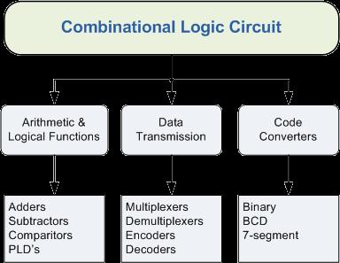
39 Combinational Logic Circuits

40 The Multiplexer A data selector, more commonly called a Multiplexer, shortened to "Mux" or "MPX", are combinational logic switching devices that operate like a very fast acting multiple position rotary switch They connect or control, multiple input lines called "channels" consisting of either 2, 4, 8 or 16 individual inputs, one at a time to an output. The job of a multiplexer is to allow multiple signals to share a single common output.


41 The 4x1 Multiplexer Addressing b a Input Selected 0 0 A 0 1 B 1 0 C 1 1 D

42 The Demultiplexer The data distributor, known more commonly as a Demultiplexer or "Demux", takes one single input data line and then switches it to any one of a number of individual output lines one at a time. The demultiplexer converts a serial data signal at the input to a parallel data at its output lines as shown below. The function of the Demultiplexer is to switch one common data input line to any one of the 4 output data lines A to D in our example above


43 The 1x4 Multiplexer Addressing b a Output Selected 0 0 A 0 1 B 1 0 C 1 1 D


44 Binary Encoder Binary Encoder takes ALL its data inputs one at a time and then converts them into a single encoded output. So we can say that a binary encoder, is a multi-input combinational logic circuit that converts the logic level "1" data at its inputs into an equivalent binary code at its output. Generally, digital encoders produce outputs of 2-bit, 3-bit or 4-bit codes depending upon the number of data input lines. (e.g. Keyboard)


45 The binary encoder Compass Binary Output Direction Q 0 Q 1 Q 2 North North-East East South-East South South-West West North-West 1 1 1


46 The Decoder Encoder is basically, a combinational type logic circuit that converts the binary code data at its input into one of a number of different output lines, one at a time producing an equivalent decimal code at its output. A decoders output code normally has more bits than its input code and practical binary decoder circuits include, 2-to-4, 3-to-8 and 4-to-16 line configurations.

47 BCD to 7-Segment Display Decoder Decoder IC, is a device which converts one digital format into another and the most commonly used device for doing this is the Binary Coded Decimal (BCD) to 7-Segment Display Decoder. A standard 7-segment LED display generally has 8 input connections, one for each LED segment and one that acts as a common terminal or connection for all the internal segments. Some single displays have an additional input pin for the decimal point in their lower right or left hand corner.
48 BCD to 7-Segment Display Decoder Individual Segments a b c d e f g Display Individual Segments a b c d e f g Display 8 9 A b C d E F
49 Binary Coded Decimal (BCD) numbers are made up using just 4 data bits similar to the Hexadecimal numbers but unlike hexadecimal numbers that range in full from 0 through to F, BCD numbers only range from 0 to 9, with the binary number patterns of 1010 through to 1111 (A to F) being invalid inputs for this type of display and so are not used BCD Numbers Decimal Binary Pattern BCD N.A.

50 BCD to 7-Segment Display Decoder
51 Binary Adder The Binary Adder is made up from standard AND and Ex-OR gates and allow us to "add" together single bit binary numbers, a and b to produce two outputs, the SUM of the addition and a CARRY called the Carry-out, ( C out ) bit Symbol Boolean Expression: Sum = A B Truth Table A B SUM CARRY Carry = A. B

52 Binary Comparator Digital or Binary Comparators are made up from standard AND, NOR and NOT gates that compare the digital signals present at their input terminals and produce an output depending upon the condition of those inputs. Inputs Outputs B A A > B A = B A < B
53 Sequential Logic Sequential Logic circuits have some form of inherent "Memory" built in to them as they are able to take into account their previous input state as well as those actually present, a sort of "before" and "after" is involved with sequential circuits. The output state of a sequential logic circuit is a function of the following three states, the "present input", the "past input" and/or the "past output". Sequential Logic circuits remember these conditions and stay fixed in their current state until the next clock signal changes one of the states, giving sequential logic circuits "Memory". Sequential logic circuits are generally termed as two state or Bistable devices which can have their output or outputs set in one of two basic states, a logic level "1" or a logic level "0" and will remain "latched" indefinitely in this current state or condition until some other input trigger pulse or signal is applied which will cause the bistable to change its state once again.

54 Sequential Logic Representation The word "Sequential" means that things happen in a "sequence", one after another and in Sequential Logic circuits, the actual clock signal determines when things will happen next. 1. Event Driven - asynchronous circuits that change state immediately when enabled. 2. Clock Driven - synchronous circuits that are synchronised to a specific clock signal. 3. Pulse Driven - which is a combination of the two that responds to triggering pulses.
55 RS Flip Flop The SR flip-flop, also known as a SR Latch, can be considered as one of the most basic sequential logic circuit possible. This simple flip-flop is basically a one-bit memory bistable device that has two inputs, one which will "SET" the device (meaning the output = "1"), and is labelled S and another which will "RESET" the device (meaning the output = "0"), labelled R. Then the SR description stands for "Set-Reset". The reset input resets the flip-flop back to its original state with an output Q that will be either at a logic level "1" or logic "0" depending upon this set/reset condition
56 RS Flip Flop Active low RS Flip flop implementation with NAND gates State S R Q Q Description Set Set Q» no change Reset Reset Q» no change Invalid memory with Q = memory with Q = 1

57 Nor gate RS Flip Flop SR Flip Flop
58 JK Flip Flop The JK flip-flop is basically a gated SR flip-flop with the addition of a clock input circuitry that prevents the illegal or invalid output condition that can occur when both inputs S and R are equal to logic level "1". Due to this additional clocked input, a JK flip-flop has four possible input combinations, "logic 1", "logic 0", "no change" and "toggle"

59 JK Flip Flop Truth Table C J K Q(n) Q(n+1) Delete ,1 0,0 Write ,0 1,1 Save ,1 0,1 Toggle ,0 0,1
60 D Flip Flop The D flip-flop is by far the most important of the clocked flip-flops as it ensures that ensures that inputs S and R are never equal to one at the same time. D-type flip-flops are constructed from a gated SR flip-flopwith an inverter added between the S and the R inputs to allow for a single D (data) input. This single data input D is used in place of the "set" signal, and the inverter is used to generate the complementary "reset" input thereby making a level-sensitive D-type flip-flop from a level-sensitive RSlatch as now S = D and R = not D

61 D Flip Flop Clk D Q Q Description» 0 X Q Q Memory no change» Reset Q» 0» Set Q» 1


62 D Flip Flop / Data Latch

63 D Flip Flop- Frequency divider
64 The Clock As seen in previous applications, Sequential Logic circuits to operate in a "sequential" way, they require the addition of a clock pulse or timing signal to cause them to change their state. Clock pulses are generally continuous square or rectangular shaped waveform that is produced by a pulse generator. This multivibrator circuit oscillates between a "HIGH" state and a "LOW" state producing a continuous output. Sequential logic circuits that use the clock signal for synchronization are dependant upon the frequency and and clock pulse width to activate there switching action.

65 The Clock Active HIGH - if the state changes occur at the clock's rising edge or during the clock width. Active LOW - if the state changes occur at the clock's falling edge. Duty Cycle - is the ratio of clock width and clock period. Clock Width - this is the time during which the value of the clock signal is equal to one. Clock Period - this is the time between successive transitions in the same direction, i.e., between two rising or two falling edges. Clock Frequency - the clock frequency is the reciprocal of the clock period, frequency = 1/clock period
66 The Clock There are basically three types of clock pulse generation circuits: Astable - A free-running multivibrator that has NO stable states but switches continuously between two states this action produces a train of square wave pulses at a fixed frequency. Monostable - A one-shot multivibrator that has only ONE stable state and is triggered externally with it returning back to its first stable state. Bistable - A flip-flop that has TWO stable states that produces a single pulse either positive or negative in value.
 to the other state (\"HIGH\") The continual switching action from \"HIGH\" to \"LOW\" and \"LOW\" to \"HIGH\" produces a continuous and stable square wave output that switches abruptly between the two")
67 NE555 Astable Multivibrator Astable Multivibrators are a type of free running oscillator that have no permanent "meta" or "steady" state but are continually changing there output from one state ("LOW") to the other state ("HIGH") The continual switching action from "HIGH" to "LOW" and "LOW" to "HIGH" produces a continuous and stable square wave output that switches abruptly between the two logic levels making it ideal for timing and clock pulse applications. t 1 = (R1 + R2) C1 t 2 = (R2) C1 T = t 1 + t 2

68 NAND Gate Monostable Circuit Monostable Multivibrators or "one-shot" pulse generators are used to convert short sharp pulses into wider ones for timing applications. Monostable multivibrators generate a single output pulse, either "high" or "low", when a suitable external trigger signal or pulse T is applied.


69 The bistable multivibrator The bistable multivibrator can be switched over from one stable state to the other by the application of an external trigger pulse thus, it requires two external trigger pulses before it returns back to its original state
70 Thanks for your interest.
Number system: the system used to count discrete units is called number. Decimal system: the number system that contains 10 distinguished
 Number system: the system used to count discrete units is called number system Decimal system: the number system that contains 10 distinguished symbols that is 0-9 or digits is called decimal system. As
Combinational Logic Circuits. Combinational Logic
 Combinational Logic Circuits The outputs of Combinational Logic Circuits are only determined by the logical function of their current input state, logic 0 or logic 1, at any given instant in time. The
HIGH LOW Astable multivibrators HIGH LOW 1:1
 1. Multivibrators A multivibrator circuit oscillates between a HIGH state and a LOW state producing a continuous output. Astable multivibrators generally have an even 50% duty cycle, that is that 50% of
UNIT-IV Combinational Logic
 UNIT-IV Combinational Logic Introduction: The signals are usually represented by discrete bands of analog levels in digital electronic circuits or digital electronics instead of continuous ranges represented
Module -18 Flip flops
 1 Module -18 Flip flops 1. Introduction 2. Comparison of latches and flip flops. 3. Clock the trigger signal 4. Flip flops 4.1. Level triggered flip flops SR, D and JK flip flops 4.2. Edge triggered flip
CS302 - Digital Logic Design Glossary By
 CS302 - Digital Logic Design Glossary By ABEL : Advanced Boolean Expression Language; a software compiler language for SPLD programming; a type of hardware description language (HDL) Adder : A digital
Digital Logic Circuits
 Digital Logic Circuits Let s look at the essential features of digital logic circuits, which are at the heart of digital computers. Learning Objectives Understand the concepts of analog and digital signals
Fan in: The number of inputs of a logic gate can handle.
 Subject Code: 17333 Model Answer Page 1/ 29 Important Instructions to examiners: 1) The answers should be examined by key words and not as word-to-word as given in the model answer scheme. 2) The model
Asst. Prof. Thavatchai Tayjasanant, PhD. Power System Research Lab 12 th Floor, Building 4 Tel: (02)
") 2145230 Aircraft Electricity and Electronics Asst. Prof. Thavatchai Tayjasanant, PhD Email: taytaycu@gmail.com aycu@g a co Power System Research Lab 12 th Floor, Building 4 Tel: (02) 218-6527 1 Chapter
2145230 Aircraft Electricity and Electronics Asst. Prof. Thavatchai Tayjasanant, PhD Email: taytaycu@gmail.com aycu@g a co Power System Research Lab 12 th Floor, Building 4 Tel: (02) 218-6527 1 Chapter
COMPUTER ORGANIZATION & ARCHITECTURE DIGITAL LOGIC CSCD211- DEPARTMENT OF COMPUTER SCIENCE, UNIVERSITY OF GHANA
 COMPUTER ORGANIZATION & ARCHITECTURE DIGITAL LOGIC LOGIC Logic is a branch of math that tries to look at problems in terms of being either true or false. It will use a set of statements to derive new true
Objective Questions. (a) Light (b) Temperature (c) Sound (d) all of these
 Light (b) Temperature (c) Sound (d) all of these") Objective Questions Module 1: Introduction 1. Which of the following is an analog quantity? (a) Light (b) Temperature (c) Sound (d) all of these 2. Which of the following is a digital quantity? (a) Electrical
Objective Questions Module 1: Introduction 1. Which of the following is an analog quantity? (a) Light (b) Temperature (c) Sound (d) all of these 2. Which of the following is a digital quantity? (a) Electrical
DESIGN OF 4 BIT BINARY ARITHMETIC CIRCUIT USING 1 S COMPLEMENT METHOD
 e-issn 2455 1392 Volume 2 Issue 4, April 2016 pp. 176-187 Scientific Journal Impact Factor : 3.468 http://www.ijcter.com DESIGN OF 4 BIT BINARY ARITHMETIC CIRCUIT USING 1 S COMPLEMENT METHOD Dhrubojyoti
MAHARASHTRA STATE BOARD OF TECHNICAL EDUCATION (Autonomous) (ISO/IEC Certified) SUMMER-16 EXAMINATION Model Answer
 (ISO/IEC Certified) SUMMER-16 EXAMINATION Model Answer") Important Instructions to examiners: 1) The answers should be examined by key words and not as word-to-word as given in the model answer scheme. 2) The model answer and the answer written by candidate
Important Instructions to examiners: 1) The answers should be examined by key words and not as word-to-word as given in the model answer scheme. 2) The model answer and the answer written by candidate
LOGIC DIAGRAM: HALF ADDER TRUTH TABLE: A B CARRY SUM. 2012/ODD/III/ECE/DE/LM Page No. 1
 LOGIC DIAGRAM: HALF ADDER TRUTH TABLE: A B CARRY SUM K-Map for SUM: K-Map for CARRY: SUM = A B + AB CARRY = AB 22/ODD/III/ECE/DE/LM Page No. EXPT NO: DATE : DESIGN OF ADDER AND SUBTRACTOR AIM: To design
LIST OF EXPERIMENTS. KCTCET/ /Odd/3rd/ETE/CSE/LM
 LIST OF EXPERIMENTS. Study of logic gates. 2. Design and implementation of adders and subtractors using logic gates. 3. Design and implementation of code converters using logic gates. 4. Design and implementation
Laboratory Manual CS (P) Digital Systems Lab
 Digital Systems Lab") Laboratory Manual CS 09 408 (P) Digital Systems Lab INDEX CYCLE I A. Familiarization of digital ICs and digital IC trainer kit 1 Verification of truth tables B. Study of combinational circuits 2. Verification
Laboratory Manual CS 09 408 (P) Digital Systems Lab INDEX CYCLE I A. Familiarization of digital ICs and digital IC trainer kit 1 Verification of truth tables B. Study of combinational circuits 2. Verification
Chapter 4: FLIP FLOPS. (Sequential Circuits) By: Siti Sabariah Hj. Salihin ELECTRICAL ENGINEERING DEPARTMENT EE 202 : DIGITAL ELECTRONICS 1
 By: Siti Sabariah Hj. Salihin ELECTRICAL ENGINEERING DEPARTMENT EE 202 : DIGITAL ELECTRONICS 1") Chapter 4: FLIP FLOPS (Sequential Circuits) By: Siti Sabariah Hj. Salihin ELECTRICAL ENGINEERING DEPARTMENT 1 CHAPTER 4 : FLIP FLOPS Programme Learning Outcomes, PLO Upon completion of the programme, graduates
Chapter 4: FLIP FLOPS (Sequential Circuits) By: Siti Sabariah Hj. Salihin ELECTRICAL ENGINEERING DEPARTMENT 1 CHAPTER 4 : FLIP FLOPS Programme Learning Outcomes, PLO Upon completion of the programme, graduates
Chapter 1: Digital logic
 Chapter 1: Digital logic I. Overview In PHYS 252, you learned the essentials of circuit analysis, including the concepts of impedance, amplification, feedback and frequency analysis. Most of the circuits
16 Multiplexers and De-multiplexers using gates and ICs. (74150, 74154)
") 16 Multiplexers and De-multiplexers using gates and ICs. (74150, 74154) Aim: To design multiplexers and De-multiplexers using gates and ICs. (74150, 74154) Components required: Digital IC Trainer kit,
16 Multiplexers and De-multiplexers using gates and ICs. (74150, 74154) Aim: To design multiplexers and De-multiplexers using gates and ICs. (74150, 74154) Components required: Digital IC Trainer kit,
SRV ENGINEERING COLLEGE SEMBODAI RUKMANI VARATHARAJAN ENGINEERING COLLEGE SEMBODAI
 SEMBODAI RUKMANI VARATHARAJAN ENGINEERING COLLEGE SEMBODAI 6489 (Approved By AICTE,Newdelhi Affiliated To ANNA UNIVERSITY::Chennai) CS 62 DIGITAL ELECTRONICS LAB (REGULATION-23) LAB MANUAL DEPARTMENT OF
Practical Workbook Logic Design & Switching Theory
 Practical Workbook Logic Design & Switching Theory Name : Year : Batch : Roll No : Department: Second Edition Fall 2017-18 Dept. of Computer & Information Systems Engineering NED University of Engineering
DIGITAL ELECTRONICS QUESTION BANK
 DIGITAL ELECTRONICS QUESTION BANK Section A: 1. Which of the following are analog quantities, and which are digital? (a) Number of atoms in a simple of material (b) Altitude of an aircraft (c) Pressure
ELECTRONICS ADVANCED SUPPLEMENTARY LEVEL
 ELECTRONICS ADVANCED SUPPLEMENTARY LEVEL AIMS The general aims of the subject are : 1. to foster an interest in and an enjoyment of electronics as a practical and intellectual discipline; 2. to develop
Department of Electronics and Communication Engineering
 Department of Electronics and Communication Engineering Sub Code/Name: BEC3L2- DIGITAL ELECTRONICS LAB Name Reg No Branch Year & Semester : : : : LIST OF EXPERIMENTS Sl No Experiments Page No Study of
Winter 14 EXAMINATION Subject Code: Model Answer P a g e 1/28
 Subject Code: 17333 Model Answer P a g e 1/28 Important Instructions to examiners: 1) The answers should be examined by key words and not as word-to-word as given in the model answer scheme. 2) The model
Course Outline Cover Page
 College of Micronesia FSM P.O. Box 159 Kolonia, Pohnpei Course Outline Cover Page Digital Electronics I VEE 135 Course Title Department and Number Course Description: This course provides the students
COMBINATIONAL and SEQUENTIAL LOGIC CIRCUITS Hardware implementation and software design
 PH-315 COMINATIONAL and SEUENTIAL LOGIC CIRCUITS Hardware implementation and software design A La Rosa I PURPOSE: To familiarize with combinational and sequential logic circuits Combinational circuits
Digital Electronics 8. Multiplexer & Demultiplexer
 1 Module -8 Multiplexers and Demultiplexers 1 Introduction 2 Principles of Multiplexing and Demultiplexing 3 Multiplexer 3.1 Types of multiplexer 3.2 A 2 to 1 multiplexer 3.3 A 4 to 1 multiplexer 3.4 Multiplex
MAHARASHTRA STATE BOARD OF TECHNICAL EDUCATION (Autonomous) (ISO/IEC Certified) MODEL ANSWER
 (ISO/IEC Certified) MODEL ANSWER") Important Instructions to examiners: 1) The answers should be examined by key words and not as word-to-word as given in the model answer scheme. 2) The model answer and the answer written by candidate
Important Instructions to examiners: 1) The answers should be examined by key words and not as word-to-word as given in the model answer scheme. 2) The model answer and the answer written by candidate
DEPARTMENT OF ELECTRICAL & ELECTRONICS ENGINEERING
 DEPARTMENT OF ELECTRICAL & ELECTRONICS ENGINEERING (Regulation 2013) EE 6311 LINEAR AND DIGITAL INTEGRATED CIRCUITS LAB MANUAL 1 SYLLABUS OBJECTIVES: Working Practice in simulators / CAD Tools / Experiment
Unit level 4 Credit value 15. Introduction. Learning Outcomes
 Unit 20: Unit code Digital Principles T/615/1494 Unit level 4 Credit value 15 Introduction While the broad field of electronics covers many aspects, it is digital electronics which now has the greatest
Chapter 3 Digital Logic Structures
 Chapter 3 Digital Logic Structures Transistor: Building Block of Computers Microprocessors contain millions of transistors Intel Pentium 4 (2): 48 million IBM PowerPC 75FX (22): 38 million IBM/Apple PowerPC
EXPERIMENT NO 1 TRUTH TABLE (1)
") EPERIMENT NO AIM: To verify the Demorgan s theorems. APPARATUS REQUIRED: THEORY: Digital logic trainer and Patch cords. The digital signals are discrete in nature and can only assume one of the two values
EPERIMENT NO AIM: To verify the Demorgan s theorems. APPARATUS REQUIRED: THEORY: Digital logic trainer and Patch cords. The digital signals are discrete in nature and can only assume one of the two values
Module 4: Design and Analysis of Combinational Circuits 1. Module-4. Design and Analysis of Combinational Circuits
 1 Module-4 Design and Analysis of Combinational Circuits 4.1 Motivation: This topic develops the fundamental understanding and design of adder, substractor, code converter multiplexer, demultiplexer etc
Electronic Instrumentation
 5V 1 1 1 2 9 10 7 CL CLK LD TE PE CO 15 + 6 5 4 3 P4 P3 P2 P1 Q4 Q3 Q2 Q1 11 12 13 14 2-14161 Electronic Instrumentation Experiment 7 Digital Logic Devices and the 555 Timer Part A: Basic Logic Gates Part
1. The decimal number 62 is represented in hexadecimal (base 16) and binary (base 2) respectively as
 and binary (base 2) respectively as") BioE 1310 - Review 5 - Digital 1/16/2017 Instructions: On the Answer Sheet, enter your 2-digit ID number (with a leading 0 if needed) in the boxes of the ID section. Fill in the corresponding numbered
BioE 1310 - Review 5 - Digital 1/16/2017 Instructions: On the Answer Sheet, enter your 2-digit ID number (with a leading 0 if needed) in the boxes of the ID section. Fill in the corresponding numbered
CS302 Digital Logic Design Solved Objective Midterm Papers For Preparation of Midterm Exam
 CS302 Digital Logic Design Solved Objective Midterm Papers For Preparation of Midterm Exam MIDTERM EXAMINATION 2011 (October-November) Q-21 Draw function table of a half adder circuit? (2) Answer: - Page
JEFFERSON COLLEGE COURSE SYLLABUS ETC255 INTRODUCTION TO DIGITAL CIRCUITS. 6 Credit Hours. Prepared by: Dennis Eimer
 JEFFERSON COLLEGE COURSE SYLLABUS ETC255 INTRODUCTION TO DIGITAL CIRCUITS 6 Credit Hours Prepared by: Dennis Eimer Revised Date: August, 2007 By Dennis Eimer Division of Technology Dr. John Keck, Dean
Spec. Instructor: Center
 PDHonline Course E379 (5 PDH) Digital Logic Circuits Volume III Spec ial Logic Circuits Instructor: Lee Layton, P.E 2012 PDH Online PDH Center 5272 Meadow Estatess Drive Fairfax, VA 22030-6658 Phone &
B.E. SEMESTER III (ELECTRICAL) SUBJECT CODE: X30902 Subject Name: Analog & Digital Electronics
 SUBJECT CODE: X30902 Subject Name: Analog & Digital Electronics") B.E. SEMESTER III (ELECTRICAL) SUBJECT CODE: X30902 Subject Name: Analog & Digital Electronics Sr. No. Date TITLE To From Marks Sign 1 To verify the application of op-amp as an Inverting Amplifier 2 To
B.E. SEMESTER III (ELECTRICAL) SUBJECT CODE: X30902 Subject Name: Analog & Digital Electronics Sr. No. Date TITLE To From Marks Sign 1 To verify the application of op-amp as an Inverting Amplifier 2 To
R & D Electronics DIGITAL IC TRAINER. Model : DE-150. Feature: Object: Specification:
 DIGITAL IC TRAINER Model : DE-150 Object: To Study the Operation of Digital Logic ICs TTL and CMOS. To Study the All Gates, Flip-Flops, Counters etc. To Study the both the basic and advance digital electronics
2 Building Blocks. There is often the need to compare two binary values.
 2 Building Blocks 2.1 Comparators There is often the need to compare two binary values. This is done using a comparator. A comparator determines whether binary values A and B are: 1. A = B 2. A < B 3.
Preface... iii. Chapter 1: Diodes and Circuits... 1
 Table of Contents Preface... iii Chapter 1: Diodes and Circuits... 1 1.1 Introduction... 1 1.2 Structure of an Atom... 2 1.3 Classification of Solid Materials on the Basis of Conductivity... 2 1.4 Atomic
IES Digital Mock Test
 . The circuit given below work as IES Digital Mock Test - 4 Logic A B C x y z (a) Binary to Gray code converter (c) Binary to ECESS- converter (b) Gray code to Binary converter (d) ECESS- To Gray code
Electronic Circuits EE359A
 Electronic Circuits EE359A Bruce McNair B206 bmcnair@stevens.edu 201-216-5549 1 Memory and Advanced Digital Circuits - 2 Chapter 11 2 Figure 11.1 (a) Basic latch. (b) The latch with the feedback loop opened.
Number of Lessons:155 #14B (P) Electronics Technology with Digital and Microprocessor Laboratory Completion Time: 42 months
 Electronics Technology with Digital and Microprocessor Laboratory Completion Time: 42 months") PROGRESS RECORD Study your lessons in the order listed below. Number of Lessons:155 #14B (P) Electronics Technology with Digital and Microprocessor Laboratory Completion Time: 42 months 1 2330A Current
PROGRESS RECORD Study your lessons in the order listed below. Number of Lessons:155 #14B (P) Electronics Technology with Digital and Microprocessor Laboratory Completion Time: 42 months 1 2330A Current
EXPERIMENT 12: DIGITAL LOGIC CIRCUITS
 EXPERIMENT 12: DIGITAL LOGIC CIRCUITS The purpose of this experiment is to gain some experience in the use of digital logic circuits. These circuits are used extensively in computers and all types of electronic
1 Signals and systems, A. V. Oppenhaim, A. S. Willsky, Prentice Hall, 2 nd edition, FUNDAMENTALS. Electrical Engineering. 2.
 1 Signals and systems, A. V. Oppenhaim, A. S. Willsky, Prentice Hall, 2 nd edition, 1996. FUNDAMENTALS Electrical Engineering 2.Processing - Analog data An analog signal is a signal that varies continuously.
Subject: Analog and Digital Electronics Code:15CS32
 Subject: Analog and Digital Electronics Code:15CS32 Syllabus: The Basic Gates : Review of Basic Logic gates, Positive and Negative Logic, Introduction to HDL. Combinational Logic Circuits:Sum-of-Products
Lecture 02: Digital Logic Review
 CENG 3420 Lecture 02: Digital Logic Review Bei Yu byu@cse.cuhk.edu.hk CENG3420 L02 Digital Logic. 1 Spring 2017 Review: Major Components of a Computer CENG3420 L02 Digital Logic. 2 Spring 2017 Review:
COMBINATIONAL CIRCUIT
 Combinational circuit is a circuit in which we combine the different gates in the circuit, for example encoder, decoder, multiplexer and demultiplexer. Some of the characteristics of combinational circuits
Digital Applications (CETT 1415) Credit: 4 semester credit hours (3 hours lecture, 4 hours lab) Prerequisite: CETT 1403 & CETT 1405
 Credit: 4 semester credit hours (3 hours lecture, 4 hours lab) Prerequisite: CETT 1403 & CETT 1405") Digital Applications () Credit: 4 semester credit hours (3 hours lecture, 4 hours lab) Prerequisite: CETT 1403 & CETT 1405 Course Description This course covers digital techniques and numbering systems,
Digital Applications () Credit: 4 semester credit hours (3 hours lecture, 4 hours lab) Prerequisite: CETT 1403 & CETT 1405 Course Description This course covers digital techniques and numbering systems,
Multivibrators. Department of Electrical & Electronics Engineering, Amrita School of Engineering
 Multivibrators Multivibrators Multivibrator is an electronic circuit that generates square, rectangular, pulse waveforms. Also called as nonlinear oscillators or function generators. Multivibrator is basically
2 Logic Gates THE INVERTER. A logic gate is an electronic circuit which makes logic decisions. It has one output and one or more inputs.
 2 Logic Gates A logic gate is an electronic circuit which makes logic decisions. It has one output and one or more inputs. THE INVERTER The inverter (NOT circuit) performs the operation called inversion
Classification of Digital Circuits
 Classification of Digital Circuits Combinational logic circuits. Output depends only on present input. Sequential circuits. Output depends on present input and present state of the circuit. Combinational
ELECTRONIC CIRCUITS. Time: Three Hours Maximum Marks: 100
 EC 40 MODEL TEST PAPER - 1 ELECTRONIC CIRCUITS Time: Three Hours Maximum Marks: 100 Answer five questions, taking ANY TWO from Group A, any two from Group B and all from Group C. All parts of a question
Associate In Applied Science In Electronics Engineering Technology Expiration Date:
 PROGRESS RECORD Study your lessons in the order listed below. Associate In Applied Science In Electronics Engineering Technology Expiration Date: 1 2330A Current and Voltage 2 2330B Controlling Current
hij Teacher Resource Bank GCE Electronics Exemplar Examination Questions ELEC2 Further Electronics
 hij Teacher Resource Bank GCE Electronics Exemplar Examination Questions ELEC2 Further Electronics The Assessment and Qualifications Alliance (AQA) is a company limited by guarantee registered in England
Linear & Digital IC Applications (BRIDGE COURSE)
") G. PULLAIAH COLLEGE OF ENGINEERING AND TECHNOLOGY Accredited by NAAC with A Grade of UGC, Approved by AICTE, New Delhi Permanently Affiliated to JNTUA, Ananthapuramu (Recognized by UGC under 2(f) and 12(B)
G. PULLAIAH COLLEGE OF ENGINEERING AND TECHNOLOGY Accredited by NAAC with A Grade of UGC, Approved by AICTE, New Delhi Permanently Affiliated to JNTUA, Ananthapuramu (Recognized by UGC under 2(f) and 12(B)
CMOS Digital Integrated Circuits Lec 11 Sequential CMOS Logic Circuits
 Lec Sequential CMOS Logic Circuits Sequential Logic In Combinational Logic circuit Out Memory Sequential The output is determined by Current inputs Previous inputs Output = f(in, Previous In) The regenerative
INTRODUCTION TO DIGITAL CONCEPT
 COURSE / CODE DIGITAL SYSTEM FUNDAMENTALS (ECE 421) DIGITAL ELECTRONICS FUNDAMENTAL (ECE 422) INTRODUCTION TO DIGITAL CONCEPT Digital and Analog Quantities Digital relates to data in the form of digits,
Digital Electronics Course Objectives
 Digital Electronics Course Objectives In this course, we learning is reported using Standards Referenced Reporting (SRR). SRR seeks to provide students with grades that are consistent, are accurate, and
Brought to you by. Priti Srinivas Sajja. PS01CMCA02 Course Content. Tutorial Practice Material. Acknowldgement References. Website pritisajja.
 Brought to you by Priti Srinivas Sajja PS01CMCA02 Course Content Tutorial Practice Material Acknowldgement References Website pritisajja.info Multiplexer Means many into one, also called data selector
Digital Electronic Concepts
 Western Technical College 10662137 Digital Electronic Concepts Course Outcome Summary Course Information Description Career Cluster Instructional Level Total Credits 4.00 Total Hours 108.00 This course
Positive and Negative Logic
 Course: B.Sc. Applied Physical Science (Computer Science) Year & Sem.: IInd Year, Sem - IIIrd Subject: Computer Science Paper No.: IX Paper Title: Computer System Architecture Lecture No.: 4 Lecture Title:
CONTENTS Sl. No. Experiment Page No
 CONTENTS Sl. No. Experiment Page No 1a Given a 4-variable logic expression, simplify it using Entered Variable Map and realize the simplified logic expression using 8:1 multiplexer IC. 2a 3a 4a 5a 6a 1b
EE 42/100 Lecture 24: Latches and Flip Flops. Rev B 4/21/2010 (2:04 PM) Prof. Ali M. Niknejad
 Prof. Ali M. Niknejad") A. M. Niknejad University of California, Berkeley EE 100 / 42 Lecture 24 p. 1/21 EE 42/100 Lecture 24: Latches and Flip Flops ELECTRONICS Rev B 4/21/2010 (2:04 PM) Prof. Ali M. Niknejad University of California,
A. M. Niknejad University of California, Berkeley EE 100 / 42 Lecture 24 p. 1/21 EE 42/100 Lecture 24: Latches and Flip Flops ELECTRONICS Rev B 4/21/2010 (2:04 PM) Prof. Ali M. Niknejad University of California,
Code No: R Set No. 1
 Code No: R05310402 Set No. 1 1. (a) What are the parameters that are necessary to define the electrical characteristics of CMOS circuits? Mention the typical values of a CMOS NAND gate. (b) Design a CMOS
EE 42/100 Lecture 24: Latches and Flip Flops. Rev A 4/14/2010 (8:30 PM) Prof. Ali M. Niknejad
 Prof. Ali M. Niknejad") A. M. Niknejad University of California, Berkeley EE 100 / 42 Lecture 24 p. 1/15 EE 42/100 Lecture 24: Latches and Flip Flops ELECTRONICS Rev A 4/14/2010 (8:30 PM) Prof. Ali M. Niknejad University of California,
A. M. Niknejad University of California, Berkeley EE 100 / 42 Lecture 24 p. 1/15 EE 42/100 Lecture 24: Latches and Flip Flops ELECTRONICS Rev A 4/14/2010 (8:30 PM) Prof. Ali M. Niknejad University of California,
NUMBER SYSTEM AND CODES
 NUMBER SYSTEM AND CODES INTRODUCTION:- The term digital refers to a process that is achieved by using discrete unit. In number system there are different symbols and each symbol has an absolute value and
Chapter 3 Describing Logic Circuits Dr. Xu
 Chapter 3 Describing Logic Circuits Dr. Xu Chapter 3 Objectives Selected areas covered in this chapter: Operation of truth tables for AND, NAND, OR, and NOR gates, and the NOT (INVERTER) circuit. Boolean
Syllabus: Digital Electronics (DE) (Project Lead The Way)
 (Project Lead The Way)") Course Overview: Digital electronics and micro computers. This is a course in applied logic that encompasses the application of electronic circuits and devices. Computer simulation software is used to
Course Overview: Digital electronics and micro computers. This is a course in applied logic that encompasses the application of electronic circuits and devices. Computer simulation software is used to
the elektor datasheet collection
 the elektor datasheet collection LM117 LM136 LM137 L200 LM236 LM317 1,2...37 V/1,5 A Shunt regulator 2,5 V -1,2...-37 V/1,5 A 2,8...36 V/2 A Shunt regulator 2,5 V 1,2...37 V/1,5 A LM320LZ-12 Fixed voltage
Dhanalakshmi College of Engineering
 Dhanalakshmi College of Engineering Manimangalam, Tambaram, Chennai 601 301 DEPARTMENT OF ELECTRICAL AND ELECTRONICS ENGINEERING EE6311 LINEAR AND DIGITAL INTEGRATED CIRCUITS LABORATORY III SEMESTER -
EXPERIMENT #5 COMBINATIONAL and SEQUENTIAL LOGIC CIRCUITS Hardware implementation and software design
 PH-315 La Rosa EXPERIMENT #5 COMINTIONL and SEUENTIL LOGIC CIRCUITS Hardware implementation and software design I PURPOSE: To familiarize with combinational and sequential logic circuits Combinational
Sr. No. Instrument Specifications. TTL (Transistor-Transistor Logic) based on bipolar junction transistors
 based on bipolar junction transistors") MIT College of Engineering, Pune. Department of Electronics & Telecommunication (Electronics Lab) EXPERIMENT NO 01 TITLE OF THE EXPERIMENT: Verify four voltage and current parameters for TTL and CMOS (IC
MIT College of Engineering, Pune. Department of Electronics & Telecommunication (Electronics Lab) EXPERIMENT NO 01 TITLE OF THE EXPERIMENT: Verify four voltage and current parameters for TTL and CMOS (IC
CHAPTER 6 DIGITAL INSTRUMENTS
 CHAPTER 6 DIGITAL INSTRUMENTS 1 LECTURE CONTENTS 6.1 Logic Gates 6.2 Digital Instruments 6.3 Analog to Digital Converter 6.4 Electronic Counter 6.6 Digital Multimeters 2 6.1 Logic Gates 3 AND Gate The
Name: Class: Date: 1. As more electronic systems have been designed using digital technology, devices have become smaller and less powerful.
 Name: Class: Date: DE Midterm Review 2 True/False Indicate whether the statement is true or false. 1. As more electronic systems have been designed using digital technology, devices have become smaller
UNIVERSITY OF BOLTON SCHOOL OF ENGINEERING BENG (HONS) ELECTRICAL & ELECTRONICS ENGINEERING SEMESTER TWO EXAMINATION 2017/2018
 ELECTRICAL & ELECTRONICS ENGINEERING SEMESTER TWO EXAMINATION 2017/2018") UNIVERSITY OF BOLTON [EES04] SCHOOL OF ENGINEERING BENG (HONS) ELECTRICAL & ELECTRONICS ENGINEERING SEMESTER TWO EXAMINATION 2017/2018 INTERMEDIATE DIGITAL ELECTRONICS AND COMMUNICATIONS MODULE NO: EEE5002
UNIVERSITY OF BOLTON [EES04] SCHOOL OF ENGINEERING BENG (HONS) ELECTRICAL & ELECTRONICS ENGINEERING SEMESTER TWO EXAMINATION 2017/2018 INTERMEDIATE DIGITAL ELECTRONICS AND COMMUNICATIONS MODULE NO: EEE5002
logic system Outputs The addition of feedback means that the state of the circuit may change with time; it is sequential. logic system Outputs
 Sequential Logic The combinational logic circuits we ve looked at so far, whether they be simple gates or more complex circuits have clearly separated inputs and outputs. A change in the input produces
R.B.V.R.R. WOMEN S COLLEGE (AUTONOMOUS) Narayanaguda, Hyderabad. ELECTRONIC PRINCIPLES AND APPLICATIONS
 Narayanaguda, Hyderabad. ELECTRONIC PRINCIPLES AND APPLICATIONS") R.B.V.R.R. WOMEN S COLLEGE (AUTONOMOUS) Narayanaguda, Hyderabad. DEPARTMENT OF PHYSICS QUESTION BANK FOR SEMESTER V PHYSICS PAPER VI (A) ELECTRONIC PRINCIPLES AND APPLICATIONS UNIT I: SEMICONDUCTOR DEVICES
R.B.V.R.R. WOMEN S COLLEGE (AUTONOMOUS) Narayanaguda, Hyderabad. DEPARTMENT OF PHYSICS QUESTION BANK FOR SEMESTER V PHYSICS PAPER VI (A) ELECTRONIC PRINCIPLES AND APPLICATIONS UNIT I: SEMICONDUCTOR DEVICES
ELECTROVATE. Electromania Problem Statement Discussion
 ELECTROVATE Electromania Problem Statement Discussion An Competition Basic Circuiting What is Electromania? Innovation Debugging Lets Revise the Basics Electronics Digital Analog Digital Electronics Similar
Chapter 3 Digital Logic Structures
 Chapter 3 Digital Logic Structures Transistor: Building Block of Computers Microprocessors contain millions of transistors Intel Pentium 4 (2000): 48 million IBM PowerPC 750FX (2002): 38 million IBM/Apple
Process Components. Process component
 What are PROCESS COMPONENTS? Input Transducer Process component Output Transducer The input transducer circuits are connected to PROCESS COMPONENTS. These components control the action of the OUTPUT components
300 in 1 Electronic Project Lab Science Fair. Tandy / RadioShack. ( ) Included Projects
 Included Projects") 300 in 1 Electronic Project Lab Science Fair Tandy / RadioShack (280-0270) Included Projects Listed below are projects included in the 280-0270 Project Kit. 1) Surprise and Fun 1. Light-Controlled Bird
300 in 1 Electronic Project Lab Science Fair Tandy / RadioShack (280-0270) Included Projects Listed below are projects included in the 280-0270 Project Kit. 1) Surprise and Fun 1. Light-Controlled Bird
Gates and Circuits 1
 1 Gates and Circuits Chapter Goals Identify the basic gates and describe the behavior of each Describe how gates are implemented using transistors Combine basic gates into circuits Describe the behavior
Digital Applications (CETT 1415) Credit: 4 semester credit hours (3 hours lecture, 4 hours lab) Prerequisite: CETT 1403 & CETT 1405
 Credit: 4 semester credit hours (3 hours lecture, 4 hours lab) Prerequisite: CETT 1403 & CETT 1405") Digital Applications (CETT 1415) Credit: 4 semester credit hours (3 hours lecture, 4 hours lab) Prerequisite: CETT 1403 & CETT 1405 Course Description This course covers digital techniques and numbering
Digital Applications (CETT 1415) Credit: 4 semester credit hours (3 hours lecture, 4 hours lab) Prerequisite: CETT 1403 & CETT 1405 Course Description This course covers digital techniques and numbering
ASTABLE MULTIVIBRATOR
 555 TIMER ASTABLE MULTIIBRATOR MONOSTABLE MULTIIBRATOR 555 TIMER PHYSICS (LAB MANUAL) PHYSICS (LAB MANUAL) 555 TIMER Introduction The 555 timer is an integrated circuit (chip) implementing a variety of
DIGITAL ELECTRONICS. Methods & diagrams : 1 Graph plotting : - Tables & analysis : - Questions & discussion : 6 Performance : 3
 DIGITAL ELECTRONICS Marking scheme : Methods & diagrams : 1 Graph plotting : - Tables & analysis : - Questions & discussion : 6 Performance : 3 Aim: This experiment will investigate the function of the
Exercise 1: AND/NAND Logic Functions
 Exercise 1: AND/NAND Logic Functions EXERCISE OBJECTIVE When you have completed this exercise, you will be able to determine the operation of an AND and a NAND logic gate. You will verify your results
COLLEGE OF ENGINEERING, NASIK
 Pune Vidyarthi Griha s COLLEGE OF ENGINEERING, NASIK LAB MANUAL DIGITAL ELECTRONICS LABORATORY Subject Code: 2246 27-8 PUNE VIDYARTHI GRIHA S COLLEGE OF ENGINEERING,NASHIK. INDEX Batch : - Sr.No Title
Digital Fundamentals 8/25/2016. Summary. Summary. Floyd. Chapter 1. Analog Quantities
 8/25/206 Digital Fundamentals Tenth Edition Floyd Chapter Analog Quantities Most natural quantities that we see are analog and vary continuously. Analog systems can generally handle higher power than digital
ANALOG TO DIGITAL (ADC) and DIGITAL TO ANALOG CONVERTERS (DAC)
 and DIGITAL TO ANALOG CONVERTERS (DAC)") COURSE / CODE DIGITAL SYSTEM FUNDAMENTALS (ECE421) DIGITAL ELECTRONICS FUNDAMENTAL (ECE422) ANALOG TO DIGITAL (ADC) and DIGITAL TO ANALOG CONVERTERS (DAC) Connecting digital circuitry to sensor devices
COURSE / CODE DIGITAL SYSTEM FUNDAMENTALS (ECE421) DIGITAL ELECTRONICS FUNDAMENTAL (ECE422) ANALOG TO DIGITAL (ADC) and DIGITAL TO ANALOG CONVERTERS (DAC) Connecting digital circuitry to sensor devices
Lecture 2: Digital Logic Basis
 Lecture 2: Digital Logic Basis Xufeng Kou School of Information Science and Technology ShanghaiTech University 1 Outline Truth Table Basic Logic Operation and Gates Logic Circuits NOR Gates and NAND Gates
 DHANALAKSHMI COLLEGE OF ENGINEERING MANIMANGALAM. TAMBARAM, CHENNAI B.E. ELECTRICAL AND ELECTRONICS ENGINEERING III SEMESTER EE6311 Linear and Digital Integrated Circuits Laboratory LABORATORY MANUAL CLASS:
Combinational Circuits: Multiplexers, Decoders, Programmable Logic Devices
 Combinational Circuits: Multiplexers, Decoders, Programmable Logic Devices Lecture 5 Doru Todinca Textbook This chapter is based on the book [RothKinney]: Charles H. Roth, Larry L. Kinney, Fundamentals
Introduction to IC-555. Compiled By: Chanakya Bhatt EE, IT-NU
 Introduction to IC-555 Compiled By: Chanakya Bhatt EE, IT-NU Introduction SE/NE 555 is a Timer IC introduced by Signetics Corporation in 1970 s. It is basically a monolithic timing circuit that produces
Digital Electronics. A. I can list five basic safety rules for electronics. B. I can properly display large and small numbers in proper notation,
 St. Michael Albertville High School Teacher: Scott Danielson September 2016 Content Skills Learning Targets Standards Assessment Resources & Technology CEQ: WHAT MAKES DIGITAL ELECTRONICS SO IMPORTANT
Logic diagram: a graphical representation of a circuit
 LOGIC AND GATES Introduction to Logic (1) Logic diagram: a graphical representation of a circuit Each type of gate is represented by a specific graphical symbol Truth table: defines the function of a gate
Chapter 4: The Building Blocks: Binary Numbers, Boolean Logic, and Gates
 Chapter 4: The Building Blocks: Binary Numbers, Boolean Logic, and Gates Objectives In this chapter, you will learn about The binary numbering system Boolean logic and gates Building computer circuits