Lecture 23 MNS 102: Techniques for Materials and Nano Sciences
|
|
|
- Owen Waters
- 6 years ago
- Views:
Transcription
1 Lecture 23 MNS 102: Techniques for Materials and Nano Sciences Reference: #1 C. R. Brundle, C. A. Evans, S. Wilson, "Encyclopedia of Materials Characterization", Butterworth-Heinemann, Toronto (1992), Ch. 2.0, 2.1 Reference: Taewoo Lee et al. Optical Microscopy of Soft Matter Systems arxiv: Reference: D.B. Murphy, Fundamentals of Light Microscopy and Electronic Imaging", Wiley, New York (2001). Light Microscopy - Overview Basic concepts: Numerical Aperture (NA), working distance (WD), resolution (R), magnification (M), depth of field or depth of focus (DOF) Types: Bright Field (BF), Dark Field (DF), Polarized Light, Differential Interference Contrast (DIC), Phase Contrast (PC). Fluorescence Microscopy Human eye can resolve ~ 0.1 mm or 100 microns 23-1

 -1,")
2 Wavelength sets Information Limit c =, where c = 3 x cm/s E = h, where h = 6.62 x erg s E = h c ( ) -1, where ( ) -1 is the wavenumber 23-2

3 Thin Lens Optics In thin lens optics Magnification (M) is defined by the ratio of the image distance to object distance, i.e., d i / d O d 0 d i Human eye ~ 0.1 mm Apparent resolvable distance by the eye for a magnified object is: R = 0.1 mm / M M R 1 100,000 nm 100 1,000 nm 1, nm 10, nm 100,000 1 nm 1,000, nm 23-3


4 Spherical aberration: Lens curvature deviates from the ideal shape, which causes different focal distances. Chromatic aberration: Lens focusses each wavelength at a different spot, but can be corrected by achromat, fluorite, or apochromat materials. Field of view flatness Immersion media Lens Imperfection 23-4
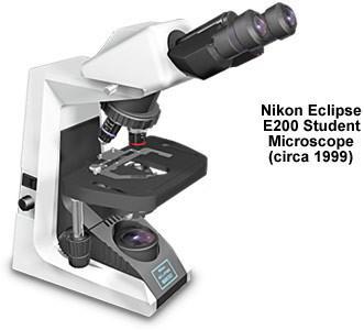

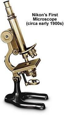
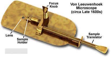
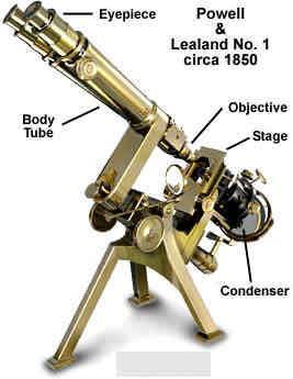
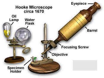

5 Optical Microscopes: History Saw single-cell organism in pond water Saw pores in cork cells 23-5


6 Basic Components > Illumination source: transmitted light vs reflected light > Condenser Lens > Specimen > Objective Lens > Viewer (eyepiece or CCD) 23-6
7 A Simple Light Microscope 23-7


8 Objective 23-8
 of an objective determines the range of angles over which the objective lens could accept light.")
 and = half-angle of the cone of light collected by the objective lens. NA < 1 for air objectives ; NA 1.5 for oil immersion objectives.")
9 Numerical Aperture & Working Distance Performance of an objective lens is defined by NA and WD. Numerical Aperture (NA) of an objective determines the range of angles over which the objective lens could accept light. NA = n sin θ, where n = refractive index of the medium between the objective lens and the sample (1 for air, 1.33 for water, 1.56 for oils) and = half-angle of the cone of light collected by the objective lens. NA < 1 for air objectives ; NA 1.5 for oil immersion objectives. Working Distance (WD) is the distance between the front lens of the objective to the specimen surface when the inspected area is in focus. This defines the max. specimen height. 23-9

 NA = Numerical Aperture = n sin where n =")
 of an objective lens; NA typically < 1 θ θ θ")

10 Spatial Resolution set by Rayleigh Criterion Resolution = shortest distance between two points that can still be separated = k / NA where k = 0.61 (Rayleigh) or 0.5 (Abbe) NA = Numerical Aperture = n sin where n = refractive index of the medium, and = semi-angle (half-angle) of an objective lens; NA typically < 1 θ θ θ Effect of NA on the image of a point. Resolution achieved by separation of Airy disks, when max of 1 st disk overlaps first min of 2 nd disk (Rayleigh)
 = [ 2 J 1 (r a) / (r a) ] 2 where a = 2 (NA) / and J 1 is the Bessel function of the first kind. Airy diffraction pattern gives the first minimum at r = W/2.")
.")
11 Resolution and PSF NA defines Point Spread Function (PSF), which is light intensity distribution in the image acquired by the microscope from a point source. PSF(r) = [ 2 J 1 (r a) / (r a) ] 2 where a = 2 (NA) / and J 1 is the Bessel function of the first kind. Airy diffraction pattern gives the first minimum at r = W/2. For two Airy discs to be resolved, they must be separated by R W/2. R is the lateral resolution and R = 0.61 / NA is the diffraction limit. Higher NA, better resolution but note R is also limited by the wavelength. Smaller WD > larger > larger NA > smaller R (i.e. better resolution). Conversely, large WD > poorer resolution
 a zoom range of 0.7 to 11.5X and (c) a 0.5X camera adapter, and the image is collected on a 2.2 megapixel camera (with a 1/1.8\" or 0.")
 = 7.6 High end: Total Mag = 1.0 x 11.5 x 0.5 x (24/0.5556) = 248.4 If we just have an eyepiece with a 10X mag, then we have 3.5 (low end) and 115 (high end).")
12 Magnification Magnification is the enlargement of the incoming angular acceptance. M = tan / tan 0 / 0 d 0 d i For a typical stereo microscope with: (a) a 0.5X objective and a 1.0X objective, (b) a zoom range of 0.7 to 11.5X and (c) a 0.5X camera adapter, and the image is collected on a 2.2 megapixel camera (with a 1/1.8" or CCD chip) and projected onto a 24 monitor. Total Magnification = (Objective Mag) x (Zoom Mag) x (Camera Adapter Mag) x (Monitor Size/CCD Chip Size) Low end: Total Mag = 0.5 x 0.7 x 0.50 x (24/ ) = 7.6 High end: Total Mag = 1.0 x 11.5 x 0.5 x (24/0.5556) = If we just have an eyepiece with a 10X mag, then we have 3.5 (low end) and 115 (high end). Olympus SZX16 Stereo microscope 23-12
13 Depth of Focus or Depth of Field (DOF) Depth of Focus refers to the image, while Depth of Field refers to the specimen. Depth of Field (or vertical resolution) measures the ability to produce a sharp image from a non-flat surface. DOF /NA for a set magnification, & can be increased by inserting an objective aperture. Light Microscope Electron Microscope Wavelength = 500 nm (150/V 0 ) = nm at 50 kv Refraction Index = n 1.5 (glass) 1.0 (vacuum) Half-angle = 70 deg 1 deg Resolution = 0.61 / NA where NA = n sin Depth of Field (DOF) = distance parallel to the optical axis that a feature on the specimen can be displaced without loss of resolution. 200 nm 0.16 nm DOF = λ n2 NA NA 2 M 2 M = 10, DOF = 60 m M = 100, DOF = 8 m M = 1,000, DOF = 200 nm 0.1 mm DOF = M θ M = 10, DOF = 1,000 m M = 100, DOF = 100 m M = 1,000, DOF = 10 m M = 10,000, DOF = 1 m 23-13

14 R vs NA Higher NA > better (smaller) R For the same NA: Smaller > better R 23-14
 and large DOF and this is mutually exclusive.")
15 DOF vs NA Higher NA > poorer (smaller) DOF For the same NA: Smaller > poorer DOF Ideally, we want small R (i.e. high resolution) and large DOF and this is mutually exclusive
16 Homework 5A: Work through the following site: When NA is increased, what happens to (a) the working distance, and (b) the brightness of the image in focus. To resolve two points separated by 1,000 nm (i.e. 1 micron) using light of 500 nm wavelength, what is the smallest NA required? Can one resolve these two points with light of 700 nm wavelength? (Use the Java app at the above site.) 23-16
 Georges Nomarski, 1955 Fluorescence Except for Fluorescence Microscopy, all five techniques involve transmission, absorption, refraction or")
17 Types of Light Microscopy Based on contrast modes and/or illumination methods: Bright Field a conventional light microscope Dark Field Polarized Light Phase contrast Fritz Zemike, Nobel Prize in Physics, 1953 Differential Interference Contrast (DIC) Georges Nomarski, 1955 Fluorescence Except for Fluorescence Microscopy, all five techniques involve transmission, absorption, refraction or scattering of light


18 Bright Field vs Dark Field Microscopy Bright Field: Image comes from direct interaction of the specimen with unpolarized white light. Processes include absorption, refraction, scattering, and reflection. Pro: Easy to perform; good contrast of dark colours. Con: Bad contrast of light colours (biological samples); overillumination. Dark Field: Image is formed by collecting only light scattered by the specimen. Oblique illumination. Direct, unscattered light is blocked. Typically used for specimen with sparse scattering objects dispersed in a non-scattering medium. Pro: Effective on highly transmitting specimens (biological samples), less artifacts (no halos). Con: Intense illumination needed and this could cause specimen damage, blind for low scattering samples


19 Köhler Illumination Kohler illumination is a technique used to provide extremely even specimen illumination and eliminate the image of the illumination source. This is achieved by making the image of light source perfectly defocussed in the sample and image planes. Homework 5B: In less than one page, discuss the difference between Kohler illumination and critical illumination. Explain how this can be achieved in an optical microscope
20 Optics Setup 23-20


21 Polarization of Light and Wollaston Prisms 23-21

22 Polarized Light Microscopy A polarizer is used to create linearly polarized light for illuminating the specimen, and a second polarizer called the analyser to infer the polarization properties of the materials. When the polarizer and analyser is crossed, the transmitted light intensity is I perpendicular = I 0 sin 2 (2 ) sin 2 ( ) where is the angle between the polarization vector and the optical axis of the birefringent material, and is the phase (= 2 n d/ ) introduced by the thickness of the material d and n is the birefringence. When the polarizer and analyser is parallel, the transmitted light intensity is I parallel = I 0 [1 sin 2 (2 ) sin 2 ( )] Linearly polarized light is split by the birefringent specimen into two components (extraordinary and ordinary), propagating at different speeds and resulting in elliptical polarization. Use pattern to deduce spatial variations of optical axis orientation and the value of n. Birefringent materials are optically anisotropic materials that have a refractive index that depends on the polarization and propagation direction of light. E.g. SiC, many plastics, CaCO 3, ice, rutile TiO
 Contrast is caused by difference in reflection,")

.")


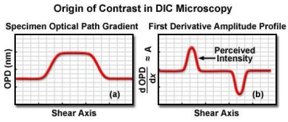
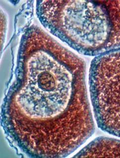
23 Differential Interference Contrast (DIC) & Phase Contrast (PC) Contrast is caused by difference in reflection, absorption, refraction, polarization, and other optical processes. DIC and PC are important for enhancing contrast in transparent specimen (e.g. cell). PC originates from the small phase shifts of light passing through a transparent specimen. DIC corresponds to interferometry due to slopes and valleys of the specimen, producing differences in the optical paths. In effect, the gradient of the refractive index within the specimen produces the DIC. BF (upper) vs DIC (lower) 23-23


24 Phase Contrast Change the phase by delaying or advancing a quarter wavelength

25 PC Microscopy Small spatial variations in phase are transformed into corresponding changes in the intensity of transmitted light. Light passes through an annular ring before the condenser lens and is focussed onto the specimen. The light can either pass through the specimen undeviated (yellow) or diffracted with a changed phase (violet) depending on the composition of the specimen. Both undeviated and diffracted beams are collected by the objective and transmitted through a phase ring to the eyepiece. The phase ring introduces an additional phase shift to the undeviated light used as the reference. Pro: Phase contrast imaging is not sensitive to polarization and birefringence effects. Good for living cells and soft materials


26 Differential Interference Contrast 23-26
 components by the first beam splitter (Nomarski-modified Wollaston prism).")
27 DIC Microscopy White light is sent to the first polarizer. The polarized light is separated into two orthogonally polarized and spatially displaced (sheared) components by the first beam splitter (Nomarski-modified Wollaston prism). Each component propagates a different path, leading to different optical path difference after existing the sample. After the objective, the two components are recombined by a second beam splitter. The polarization of the resulting light is then analysed by the second polarizer (the analyser). The result is that the optical path length gradient along the shear direction will enhance contrast due to edges and interfaces of the specimen with different refractive indices. More gradient > more contrast
28 Transmitted Light vs Reflected Light Illumination Thus far, we talk about transmitted light illumination, i.e. light from the illumination source passes through the specimen and is detected on the other side (the objective side). Here, light absorption is an important process, along with diffraction. We can also use reflected light illumination, i.e. light from the illumination source comes from the top of the specimen (not below the specimen). Here, light reflection (along with diffraction) is an important process b/c the objective is on the same side of the light illumination. Reflected light illumination is more popular in commercial microscopes


29 BF vs DF Reflected Light Illumination Setup 23-29


30 PL & DIC Reflected Light Illumination Setup 23-30


31 Contrast Modes vs Image Quality BF DIC PL DF 23-31


32 Fluorescence Use of fluorescence in microscopy is very important to quantitative biology. Images show locations of the fluorescent markers. All non-stained tissue remains transparent. Amount of fluorescence can be measured accurately. This has led to recent advances in super-resolution microscopy, with resolution going below 60 nm


33 Fluorescent Materials Small organic dye molecules Fluorescent proteins Green FP - M. Chalfie, O. Shimomura, R.Y. Tsien, Nobel Prize in Chemistry 2008 Quantum dots 23-33
, relaxation of dye (lower). Dye could be carcinogenic.")
34 Glow-stick & Chemiluminescence Oxidation of an diphenyl oxalate (top), decomposition of 1,2-dioxetanedione (middle), relaxation of dye (lower). Dye could be carcinogenic
 emission of light at a longer wavelength. The lifetime of the excited state is usually in nanoseconds.")
35 Fluorescence Microscopy Based on fluorescence phenomenon: (a) absorption of light by fluorescent dye molecules or fluorophores at a specific wavelength, thereby promoting to an excited state, followed by (b) emission of light at a longer wavelength. The lifetime of the excited state is usually in nanoseconds. The shift between the absorption peak and emission peak is called the Stokes shift and it is caused by nonradiative processes. This allows the use of optical filters to separate the excitation and emission signals. A filter cube contains an excitation filter, a dichroic mirror and an emission filter. Dichroic mirror is a very accurate mirror that reflects light of a small range of colours (wavelengths) while passing the other colours


36 Epifluorescence Microscope Thick section of human skin: green = anti-basal lamina proten; red = neuronal processes; blue = collagen and elastin auto fluoresce Source: Pollen 23-36
37 Homework 5C: Discuss in one page or less, the difference between epifluorescence and transfluorescence. Identify the advantage of the former
Microscopy: Fundamental Principles and Practical Approaches
 Microscopy: Fundamental Principles and Practical Approaches Simon Atkinson Online Resource: http://micro.magnet.fsu.edu/primer/index.html Book: Murphy, D.B. Fundamentals of Light Microscopy and Electronic
Introduction to Light Microscopy. (Image: T. Wittman, Scripps)
") Introduction to Light Microscopy (Image: T. Wittman, Scripps) The Light Microscope Four centuries of history Vibrant current development One of the most widely used research tools A. Khodjakov et al. Major
Introduction to Light Microscopy (Image: T. Wittman, Scripps) The Light Microscope Four centuries of history Vibrant current development One of the most widely used research tools A. Khodjakov et al. Major
Imaging Introduction. September 24, 2010
 Imaging Introduction September 24, 2010 What is a microscope? Merriam-Webster: an optical instrument consisting of a lens or combination of lenses for making enlarged images of minute objects; especially:
VISUAL PHYSICS ONLINE DEPTH STUDY: ELECTRON MICROSCOPES
 VISUAL PHYSICS ONLINE DEPTH STUDY: ELECTRON MICROSCOPES Shortly after the experimental confirmation of the wave properties of the electron, it was suggested that the electron could be used to examine objects
Very short introduction to light microscopy and digital imaging
 Very short introduction to light microscopy and digital imaging Hernan G. Garcia August 1, 2005 1 Light Microscopy Basics In this section we will briefly describe the basic principles of operation and
FLUORESCENCE MICROSCOPY. Matyas Molnar and Dirk Pacholsky
 FLUORESCENCE MICROSCOPY Matyas Molnar and Dirk Pacholsky 1 The human eye perceives app. 400-700 nm; best at around 500 nm (green) Has a general resolution down to150-300 μm (human hair: 40-250 μm) We need
Resolution. Diffraction from apertures limits resolution. Rayleigh criterion θ Rayleigh = 1.22 λ/d 1 peak at 2 nd minimum. θ f D
 Microscopy Outline 1. Resolution and Simple Optical Microscope 2. Contrast enhancement: Dark field, Fluorescence (Chelsea & Peter), Phase Contrast, DIC 3. Newer Methods: Scanning Tunneling microscopy (STM),
Microscope anatomy, image formation and resolution
 Microscope anatomy, image formation and resolution Ian Dobbie Buy this book for your lab: D.B. Murphy, "Fundamentals of light microscopy and electronic imaging", ISBN 0-471-25391-X Visit these websites:
BASICS IN BIOIMAGING AND OPTICS PLATFORM EPFL SV PTBIOP LIGHT MICROSCOPY
 BASICS IN LIGHT MICROSCOPY OVERVIEW 1. Motivation 2. Basic in optics 3. How microscope works 4. Illumination and resolution 5. Microscope optics 6. Contrasting methods -2- MOTIVATION Why do we need microscopy?
Microscopy Training & Overview
 Microscopy Training & Overview Product Marketing October 2011 Stephan Briggs - PLE OVERVIEW AND PRESENTATION FLOW Glossary and Important Terms Introduction Timeline Innovation and Advancement Primary Components
Point Spread Function. Confocal Laser Scanning Microscopy. Confocal Aperture. Optical aberrations. Alternative Scanning Microscopy
 Bi177 Lecture 5 Adding the Third Dimension Wide-field Imaging Point Spread Function Deconvolution Confocal Laser Scanning Microscopy Confocal Aperture Optical aberrations Alternative Scanning Microscopy
Reflection! Reflection and Virtual Image!
 1/30/14 Reflection - wave hits non-absorptive surface surface of a smooth water pool - incident vs. reflected wave law of reflection - concept for all electromagnetic waves - wave theory: reflected back
ANSWER KEY Lab 2 (IGB): Bright Field and Fluorescence Optical Microscopy and Sectioning
: Bright Field and Fluorescence Optical Microscopy and Sectioning") Phys598BP Spring 2016 University of Illinois at Urbana-Champaign ANSWER KEY Lab 2 (IGB): Bright Field and Fluorescence Optical Microscopy and Sectioning Location: IGB Core Microscopy Facility Microscope:
Phys598BP Spring 2016 University of Illinois at Urbana-Champaign ANSWER KEY Lab 2 (IGB): Bright Field and Fluorescence Optical Microscopy and Sectioning Location: IGB Core Microscopy Facility Microscope:
PHYSICS. Chapter 35 Lecture FOR SCIENTISTS AND ENGINEERS A STRATEGIC APPROACH 4/E RANDALL D. KNIGHT
 PHYSICS FOR SCIENTISTS AND ENGINEERS A STRATEGIC APPROACH 4/E Chapter 35 Lecture RANDALL D. KNIGHT Chapter 35 Optical Instruments IN THIS CHAPTER, you will learn about some common optical instruments and
Microscopy. Matti Hotokka Department of Physical Chemistry Åbo Akademi University
 Microscopy Matti Hotokka Department of Physical Chemistry Åbo Akademi University What s coming Anatomy of a microscope Modes of illumination Practicalities Special applications Basic microscope Ocular
Light microscopy BMB 173, Lecture 14, Feb. 21, 2018
 Light microscopy The Structural Biology Continuum Next two lectures: Light microscopy Many slides taken from Scott Fraser, Murphy s Fundamentals of light microscopy, Alberts Molecular Biology of the Cell,
The Nature of Light. Light and Energy
 The Nature of Light Light and Energy - dependent on energy from the sun, directly and indirectly - solar energy intimately associated with existence of life -light absorption: dissipate as heat emitted
microscopy A great online resource Molecular Expressions, a Microscope Primer Partha Roy
 Fundamentals of optical microscopy A great online resource Molecular Expressions, a Microscope Primer http://micro.magnet.fsu.edu/primer/index.html Partha Roy 1 Why microscopy Topics Functions of a microscope
SUBJECT: PHYSICS. Use and Succeed.
 SUBJECT: PHYSICS I hope this collection of questions will help to test your preparation level and useful to recall the concepts in different areas of all the chapters. Use and Succeed. Navaneethakrishnan.V
Heisenberg) relation applied to space and transverse wavevector
 relation applied to space and transverse wavevector") 2. Optical Microscopy 2.1 Principles A microscope is in principle nothing else than a simple lens system for magnifying small objects. The first lens, called the objective, has a short focal length (a
2. Optical Microscopy 2.1 Principles A microscope is in principle nothing else than a simple lens system for magnifying small objects. The first lens, called the objective, has a short focal length (a
CCAM Microscope Objectives
 CCAM Microscope Objectives Things to consider when selecting an objective Magnification Numerical Aperture (NA) resolving power and light intensity of the objective Working Distance distance between the
Education in Microscopy and Digital Imaging
 Contact Us Carl Zeiss Education in Microscopy and Digital Imaging ZEISS Home Products Solutions Support Online Shop ZEISS International ZEISS Campus Home Interactive Tutorials Basic Microscopy Spectral
Applied Optics. , Physics Department (Room #36-401) , ,
 , ,") Applied Optics Professor, Physics Department (Room #36-401) 2290-0923, 019-539-0923, shsong@hanyang.ac.kr Office Hours Mondays 15:00-16:30, Wednesdays 15:00-16:30 TA (Ph.D. student, Room #36-415) 2290-0921,
Applied Optics Professor, Physics Department (Room #36-401) 2290-0923, 019-539-0923, shsong@hanyang.ac.kr Office Hours Mondays 15:00-16:30, Wednesdays 15:00-16:30 TA (Ph.D. student, Room #36-415) 2290-0921,
INTRODUCTION THIN LENSES. Introduction. given by the paraxial refraction equation derived last lecture: Thin lenses (19.1) = 1. Double-lens systems
 = 1. Double-lens systems") Chapter 9 OPTICAL INSTRUMENTS Introduction Thin lenses Double-lens systems Aberrations Camera Human eye Compound microscope Summary INTRODUCTION Knowledge of geometrical optics, diffraction and interference,
Chapter 9 OPTICAL INSTRUMENTS Introduction Thin lenses Double-lens systems Aberrations Camera Human eye Compound microscope Summary INTRODUCTION Knowledge of geometrical optics, diffraction and interference,
 Microscopy http://www.microscopyu.com/articles/phasecontrast/phasemicroscopy.html http://micro.magnet.fsu.edu/primer/anatomy/anatomy.html 2005, Dr. Jack Ikeda & Dr. Gail Grabner 9 Nikon Labophot (Question
Basics of confocal imaging (part I)
") Basics of confocal imaging (part I) Swiss Institute of Technology (EPFL) Faculty of Life Sciences Head of BIOIMAGING AND OPTICS BIOP arne.seitz@epfl.ch Lateral resolution BioImaging &Optics Platform Light
Basics of confocal imaging (part I) Swiss Institute of Technology (EPFL) Faculty of Life Sciences Head of BIOIMAGING AND OPTICS BIOP arne.seitz@epfl.ch Lateral resolution BioImaging &Optics Platform Light
Confocal Microscopy and Related Techniques
 Confocal Microscopy and Related Techniques Chau-Hwang Lee Associate Research Fellow Research Center for Applied Sciences, Academia Sinica 128 Sec. 2, Academia Rd., Nankang, Taipei 11529, Taiwan E-mail:
Motorized Axio Observer Start-up instructions
 Start-up instructions 1. If using fluorescence turn on Fluorescent light source. TL light Source (Hal 100) 2. Turn on microscope using switch on lower left side of the microscope. 3. If imaging, turn on
CCAM s Selection of. Zeiss Microscope Objectives
 CCAM s Selection of Zeiss Microscope Objectives 1. Magnification Image scale 2. Resolution The minimum separation distance between two points that are clearly resolved. The resolution of an objective is
Script Bio 407 Applied Microscopy Light microscopy
 Center for Microscopy and Image Analysis Dr. José María Mateos Center for Microscopy and Image Analysis Winterthurerstrasse 190 CH-8057 Zurich Phone 044 635 98 20 mateos@zmb.uzh.ch www.zmb.uzh.ch Script
Light Microscopy. Upon completion of this lecture, the student should be able to:
 Light Light microscopy is based on the interaction of light and tissue components and can be used to study tissue features. Upon completion of this lecture, the student should be able to: 1- Explain the
Katarina Logg, Kristofer Bodvard, Mikael Käll. Dept. of Applied Physics. 12 September Optical Microscopy. Supervisor s signature:...
 Katarina Logg, Kristofer Bodvard, Mikael Käll Dept. of Applied Physics 12 September 2007 O1 Optical Microscopy Name:.. Date:... Supervisor s signature:... Introduction Over the past decades, the number
OPELCO OPtical ELements COrporation LB Objective Series for Biological Use
 LB Objective Series for Biological Use 105 Executive Drive Suite 100 Dulles, VA 20166-9558 Tel: (703) 471-0080 S PLAN APOCHROMAT OBJECTIVES These objectives compensate for three wavelength of chromatic
Bio 407. Applied microscopy. Introduction into light microscopy. José María Mateos. Center for Microscopy and Image Analysis
 Center for Microscopy and Image Analysis Bio 407 Applied Introduction into light José María Mateos Fundamentals of light Compound microscope Microscope composed of an objective and an additional lens (eyepiece,
Chapter 25. Optical Instruments
 Chapter 25 Optical Instruments Optical Instruments Analysis generally involves the laws of reflection and refraction Analysis uses the procedures of geometric optics To explain certain phenomena, the wave
R.B.V.R.R. WOMEN S COLLEGE (AUTONOMOUS) Narayanaguda, Hyderabad.
 Narayanaguda, Hyderabad.") R.B.V.R.R. WOMEN S COLLEGE (AUTONOMOUS) Narayanaguda, Hyderabad. DEPARTMENT OF PHYSICS QUESTION BANK FOR SEMESTER III PAPER III OPTICS UNIT I: 1. MATRIX METHODS IN PARAXIAL OPTICS 2. ABERATIONS UNIT II
R.B.V.R.R. WOMEN S COLLEGE (AUTONOMOUS) Narayanaguda, Hyderabad. DEPARTMENT OF PHYSICS QUESTION BANK FOR SEMESTER III PAPER III OPTICS UNIT I: 1. MATRIX METHODS IN PARAXIAL OPTICS 2. ABERATIONS UNIT II
LSM 510 META in Chang Gung University
 Content LSM 510 META in Chang ung University LSM 510 META 路 理 The features and applications of LSM 510 META 01-09 Introduction of the hardware 10-12 Fluorescence observation in conventional microscope
Rates of excitation, emission, ISC
 Bi177 Lecture 4 Fluorescence Microscopy Phenomenon of Fluorescence Energy Diagram Rates of excitation, emission, ISC Practical Issues Lighting, Filters More on diffraction Point Spread Functions Thus Far,
INTRODUCTION TO OPTICAL MICROSCOPY
 Experimental Biophysics TEK265, FYST23, TNF060, FAF010F Lab Exercise Supervisor: Karl Adolfsson Written by Peter Jönsson and Jason Beech Updated by Henrik Persson, Karl Adolfsson and Zhen Li karl.adolfsson@ftf.lth.se
Chapter Ray and Wave Optics
 109 Chapter Ray and Wave Optics 1. An astronomical telescope has a large aperture to [2002] reduce spherical aberration have high resolution increase span of observation have low dispersion. 2. If two
Final Exam, 150 points PMB 185: Techniques in Light Microscopy
 Final Exam, 150 points Name PMB 185: Techniques in Light Microscopy Point value is in parentheses at the end of each question. Note: GFP = green fluorescent protein ; CFP = cyan fluorescent protein ; YFP
Lecture 8. Lecture 8. r 1
 Lecture 8 Achromat Design Design starts with desired Next choose your glass materials, i.e. Find P D P D, then get f D P D K K Choose radii (still some freedom left in choice of radii for minimization
BASICS IN LIGHT MICROSCOPY
 BASICS IN LIGHT MICROSCOPY INTERNAL COURSE 2015 26 TH JANUARY OVERVIEW Light microscopy Why do we need it? How does it work? What are its limitations? What do we need to consider? - 2 - HUMAN EYE Normal
Electron
 Electron 1897: Sir Joseph John Thomson (1856-1940) discovered corpuscles small particles with a charge-to-mass ratio over 1000 times greater than that of protons. Plum pudding model : electrons in a sea
Exercise 8: Interference and diffraction
 Physics 223 Name: Exercise 8: Interference and diffraction 1. In a two-slit Young s interference experiment, the aperture (the mask with the two slits) to screen distance is 2.0 m, and a red light of wavelength
Practical Flatness Tech Note
 Practical Flatness Tech Note Understanding Laser Dichroic Performance BrightLine laser dichroic beamsplitters set a new standard for super-resolution microscopy with λ/10 flatness per inch, P-V. We ll
Advanced Optical Microscopy
 Nanosystems I - Seminar TU München 8th December 2008 1 Introduction to Classical Optical Microscopy Denitions in Optical Microscopy Contrast and Contrast Enhancement 1 Introduction to Classical Optical
Chapter 3 Op,cal Instrumenta,on
 Imaging by an Op,cal System Change in curvature of wavefronts by a thin lens Chapter 3 Op,cal Instrumenta,on 3-1 Stops, Pupils, and Windows 3-4 The Camera 3-5 Simple Magnifiers and Eyepieces 1. Magnifiers
Chapter 16 Light Waves and Color
 Chapter 16 Light Waves and Color Lecture PowerPoint Copyright The McGraw-Hill Companies, Inc. Permission required for reproduction or display. What causes color? What causes reflection? What causes color?
Systems Biology. Optical Train, Köhler Illumination
 McGill University Life Sciences Complex Imaging Facility Systems Biology Microscopy Workshop Tuesday December 7 th, 2010 Simple Lenses, Transmitted Light Optical Train, Köhler Illumination What Does a
BEAM HALO OBSERVATION BY CORONAGRAPH
 BEAM HALO OBSERVATION BY CORONAGRAPH T. Mitsuhashi, KEK, TSUKUBA, Japan Abstract We have developed a coronagraph for the observation of the beam halo surrounding a beam. An opaque disk is set in the beam
Basics of Light Microscopy and Metallography
 ENGR45: Introduction to Materials Spring 2012 Laboratory 8 Basics of Light Microscopy and Metallography In this exercise you will: gain familiarity with the proper use of a research-grade light microscope
Biology 29 Cell Structure and Function Spring, 2009 Springer LABORATORY 1: THE LIGHT MICROSCOPE
 Biology 29 Cell Structure and Function Spring, 2009 Springer LABORATORY 1: THE LIGHT MICROSCOPE Prior to lab: 1) Read these instructions (p 1-6) 2) Go through the online tutorial, the microscopy pre-lab
Introduction to light microscopy
 Center for Microscopy and Image Anaylsis Introduction to light Basic concepts of imaging with light Urs Ziegler ziegler@zmb.uzh.ch Microscopy with light 1 Light interacting with matter Absorbtion Refraction
Applications of Optics
 Nicholas J. Giordano www.cengage.com/physics/giordano Chapter 26 Applications of Optics Marilyn Akins, PhD Broome Community College Applications of Optics Many devices are based on the principles of optics
Observing Microorganisms through a Microscope LIGHT MICROSCOPY: This type of microscope uses visible light to observe specimens. Compound Light Micros
 PHARMACEUTICAL MICROBIOLOGY JIGAR SHAH INSTITUTE OF PHARMACY NIRMA UNIVERSITY Observing Microorganisms through a Microscope LIGHT MICROSCOPY: This type of microscope uses visible light to observe specimens.
ELECTRON MICROSCOPY. 13:10 16:00, Oct. 6, 2008 Institute of Physics, Academia Sinica. Tung Hsu
 ELECTRON MICROSCOPY 13:10 16:00, Oct. 6, 2008 Institute of Physics, Academia Sinica Tung Hsu Department of Materials Science and Engineering National Tsing Hua University Hsinchu 300, TAIWAN Tel. 03-5742564
BIOIMAGING AND OPTICS PLATFORM EPFL SV PTBIOP BASICS IN LIGHT MICROSCOPY
 BASICS IN LIGHT MICROSCOPY INTERNAL COURSE 2014 13 TH JANUARY OVERVIEW 1. Motivation 2. Basic in optics 3. How microscope works 4. Illumination and resolution 5. Microscope optics 6. Contrasting methods
GIST OF THE UNIT BASED ON DIFFERENT CONCEPTS IN THE UNIT (BRIEFLY AS POINT WISE). RAY OPTICS
. RAY OPTICS") 209 GIST OF THE UNIT BASED ON DIFFERENT CONCEPTS IN THE UNIT (BRIEFLY AS POINT WISE). RAY OPTICS Reflection of light: - The bouncing of light back into the same medium from a surface is called reflection
209 GIST OF THE UNIT BASED ON DIFFERENT CONCEPTS IN THE UNIT (BRIEFLY AS POINT WISE). RAY OPTICS Reflection of light: - The bouncing of light back into the same medium from a surface is called reflection
Tissue Preparation ORGANISM IMAGE TISSUE PREPARATION. 1) Fixation: halts cell metabolism, preserves cell/tissue structure
 Fixation: halts cell metabolism, preserves cell/tissue structure") Lab starts this week! ANNOUNCEMENTS - Tuesday or Wednesday 1:25 ISB 264 - Read Lab 1: Microscopy and Imaging (see Web Page) - Getting started on Lab Group project - Organ for investigation - Lab project
Lab starts this week! ANNOUNCEMENTS - Tuesday or Wednesday 1:25 ISB 264 - Read Lab 1: Microscopy and Imaging (see Web Page) - Getting started on Lab Group project - Organ for investigation - Lab project
Examination, TEN1, in courses SK2500/SK2501, Physics of Biomedical Microscopy,
 KTH Applied Physics Examination, TEN1, in courses SK2500/SK2501, Physics of Biomedical Microscopy, 2009-06-05, 8-13, FB51 Allowed aids: Compendium Imaging Physics (handed out) Compendium Light Microscopy
OPTICS GLOSSARY A BRIEF EXPLANATION OF CERTAIN OPTICAL TERMS PRE1305 OPTICAL MEASURING
 OPTICS GLOSSARY A BRIEF EXPLANATION OF CERTAIN OPTICAL TERMS OPTICAL MEASURING PRE1305 INTRODUCTION INTRODUCTION With seven decades of experience and more than 5,000 specialized products, Mitutoyo is
Digital Camera Technologies for Scientific Bio-Imaging. Part 2: Sampling and Signal
 Digital Camera Technologies for Scientific Bio-Imaging. Part 2: Sampling and Signal Yashvinder Sabharwal, 1 James Joubert 2 and Deepak Sharma 2 1. Solexis Advisors LLC, Austin, TX, USA 2. Photometrics
Optical Components for Laser Applications. Günter Toesko - Laserseminar BLZ im Dezember
 Günter Toesko - Laserseminar BLZ im Dezember 2009 1 Aberrations An optical aberration is a distortion in the image formed by an optical system compared to the original. It can arise for a number of reasons
CHAPTER TWO METALLOGRAPHY & MICROSCOPY
 CHAPTER TWO METALLOGRAPHY & MICROSCOPY 1. INTRODUCTION: Materials characterisation has two main aspects: Accurately measuring the physical, mechanical and chemical properties of materials Accurately measuring
Introduction to light microscopy
 Center for Microscopy and Image Anaylsis Introduction to light microscopy Basic concepts of imaging with light Urs Ziegler ziegler@zmb.uzh.ch Light interacting with matter Absorbtion Refraction Diffraction
Lecture 2: Geometrical Optics. Geometrical Approximation. Lenses. Mirrors. Optical Systems. Images and Pupils. Aberrations.
 Lecture 2: Geometrical Optics Outline 1 Geometrical Approximation 2 Lenses 3 Mirrors 4 Optical Systems 5 Images and Pupils 6 Aberrations Christoph U. Keller, Leiden Observatory, keller@strw.leidenuniv.nl
The Compound Microscope. Brightfield: Köhler Illumination
 Outline History of Microscopy The Magnifying Glass The Compound Microscope Brightfield: Köhler Illumination Microscopy µικροσ (mikros): small σκοπειν (skopein): to observe History of Microscopy Well :
a) How big will that physical image of the cells be your camera sensor?
 How big will that physical image of the cells be your camera sensor?") 1. Consider a regular wide-field microscope set up with a 60x, NA = 1.4 objective and a monochromatic digital camera with 8 um pixels, properly positioned in the primary image plane. This microscope is
1. Consider a regular wide-field microscope set up with a 60x, NA = 1.4 objective and a monochromatic digital camera with 8 um pixels, properly positioned in the primary image plane. This microscope is
Section A Conceptual and application type questions. 1 Which is more observable diffraction of light or sound? Justify. (1)
") INDIAN SCHOOL MUSCAT Department of Physics Class : XII Physics Worksheet - 6 (2017-2018) Chapter 9 and 10 : Ray Optics and wave Optics Section A Conceptual and application type questions 1 Which is more
INDIAN SCHOOL MUSCAT Department of Physics Class : XII Physics Worksheet - 6 (2017-2018) Chapter 9 and 10 : Ray Optics and wave Optics Section A Conceptual and application type questions 1 Which is more
BASICS OF CONFOCAL IMAGING (PART I)
") BASICS OF CONFOCAL IMAGING (PART I) INTERNAL COURSE 2012 LIGHT MICROSCOPY Lateral resolution Transmission Fluorescence d min 1.22 NA obj NA cond 0 0 rairy 0.61 NAobj Ernst Abbe Lord Rayleigh Depth of field
BASICS OF CONFOCAL IMAGING (PART I) INTERNAL COURSE 2012 LIGHT MICROSCOPY Lateral resolution Transmission Fluorescence d min 1.22 NA obj NA cond 0 0 rairy 0.61 NAobj Ernst Abbe Lord Rayleigh Depth of field
ELECTRON MICROSCOPY. 14:10 17:00, Apr. 3, 2007 Department of Physics, National Taiwan University. Tung Hsu
 ELECTRON MICROSCOPY 14:10 17:00, Apr. 3, 2007 Department of Physics, National Taiwan University Tung Hsu Department of Materials Science and Engineering National Tsinghua University Hsinchu 300, TAIWAN
ECEN. Spectroscopy. Lab 8. copy. constituents HOMEWORK PR. Figure. 1. Layout of. of the
 ECEN 4606 Lab 8 Spectroscopy SUMMARY: ROBLEM 1: Pedrotti 3 12-10. In this lab, you will design, build and test an optical spectrum analyzer and use it for both absorption and emission spectroscopy. The
Chapter 3 Op+cal Instrumenta+on
 Chapter 3 Op+cal Instrumenta+on 3-1 Stops, Pupils, and Windows 3-4 The Camera 3-5 Simple Magnifiers and Eyepieces 3-6 Microscopes 3-7 Telescopes Today (2011-09-22) 1. Magnifiers 2. Camera 3. Resolution
General Physics II. Ray Optics
 General Physics II Ray Optics 1 Dispersion White light is a combination of all the wavelengths of the visible part of the electromagnetic spectrum. Red light has the longest wavelengths and violet light
EE119 Introduction to Optical Engineering Spring 2003 Final Exam. Name:
 EE119 Introduction to Optical Engineering Spring 2003 Final Exam Name: SID: CLOSED BOOK. THREE 8 1/2 X 11 SHEETS OF NOTES, AND SCIENTIFIC POCKET CALCULATOR PERMITTED. TIME ALLOTTED: 180 MINUTES Fundamental
DOING PHYSICS WITH MATLAB COMPUTATIONAL OPTICS. GUI Simulation Diffraction: Focused Beams and Resolution for a lens system
 DOING PHYSICS WITH MATLAB COMPUTATIONAL OPTICS GUI Simulation Diffraction: Focused Beams and Resolution for a lens system Ian Cooper School of Physics University of Sydney ian.cooper@sydney.edu.au DOWNLOAD
Optical Design of. Microscopes. George H. Seward. Tutorial Texts in Optical Engineering Volume TT88. SPIE PRESS Bellingham, Washington USA
 Optical Design of Microscopes George H. Seward Tutorial Texts in Optical Engineering Volume TT88 SPIE PRESS Bellingham, Washington USA Preface xiii Chapter 1 Optical Design Concepts /1 1.1 A Value Proposition
TSBB09 Image Sensors 2018-HT2. Image Formation Part 1
 TSBB09 Image Sensors 2018-HT2 Image Formation Part 1 Basic physics Electromagnetic radiation consists of electromagnetic waves With energy That propagate through space The waves consist of transversal
PHYSICS FOR THE IB DIPLOMA CAMBRIDGE UNIVERSITY PRESS
 Option C Imaging C Introduction to imaging Learning objectives In this section we discuss the formation of images by lenses and mirrors. We will learn how to construct images graphically as well as algebraically.
Will contain image distance after raytrace Will contain image height after raytrace
 Name: LASR 51 Final Exam May 29, 2002 Answer all questions. Module numbers are for guidance, some material is from class handouts. Exam ends at 8:20 pm. Ynu Raytracing The first questions refer to the
Characterization Methods. Prof.Dr.Figen KAYA A-209
 Characterization Methods Prof.Dr.Figen KAYA fkaya@yildiz.edu.tr A-209 References Materials Characterization. Introduction to Microscopic and Spectroscopic Methods, Yang Leng, JohnWiley &Sons Ltd, ISBN:
Lecture 2: Geometrical Optics. Geometrical Approximation. Lenses. Mirrors. Optical Systems. Images and Pupils. Aberrations.
 Lecture 2: Geometrical Optics Outline 1 Geometrical Approximation 2 Lenses 3 Mirrors 4 Optical Systems 5 Images and Pupils 6 Aberrations Christoph U. Keller, Leiden Observatory, keller@strw.leidenuniv.nl
Supplementary Information for. Surface Waves. Angelo Angelini, Elsie Barakat, Peter Munzert, Luca Boarino, Natascia De Leo,
 Supplementary Information for Focusing and Extraction of Light mediated by Bloch Surface Waves Angelo Angelini, Elsie Barakat, Peter Munzert, Luca Boarino, Natascia De Leo, Emanuele Enrico, Fabrizio Giorgis,
Prof. Enrico Gratton - Lecture 6 Fluorescence Microscopy
 Prof. Enrico Gratton - Lecture 6 Fluorescence Microscopy Instrumentation Light Sources: One-photon and Multi-photon Excitation Applications in Cells Lifetime Imaging Figures acknowledgements: E.D. Salmon
MICROSCOPE LAB. Resolving Power How well specimen detail is preserved during the magnifying process.
 AP BIOLOGY Cells ACTIVITY #2 MICROSCOPE LAB OBJECTIVES 1. Demonstrate proper care and use of a compound microscope. 2. Identify the parts of the microscope and describe the function of each part. 3. Compare
Development of a High-speed Super-resolution Confocal Scanner
 Development of a High-speed Super-resolution Confocal Scanner Takuya Azuma *1 Takayuki Kei *1 Super-resolution microscopy techniques that overcome the spatial resolution limit of conventional light microscopy
ECEN 4606, UNDERGRADUATE OPTICS LAB
 ECEN 4606, UNDERGRADUATE OPTICS LAB Lab 3: Imaging 2 the Microscope Original Version: Professor McLeod SUMMARY: In this lab you will become familiar with the use of one or more lenses to create highly
A broadband achromatic metalens for focusing and imaging in the visible
 SUPPLEMENTARY INFORMATION Articles https://doi.org/10.1038/s41565-017-0034-6 In the format provided by the authors and unedited. A broadband achromatic metalens for focusing and imaging in the visible
Microscopy. Lecture 2: Optical System of the Microscopy II Herbert Gross. Winter term
 Microscopy Lecture 2: Optical System of the Microscopy II 212-1-22 Herbert Gross Winter term 212 www.iap.uni-jena.de Preliminary time schedule 2 No Date Main subject Detailed topics Lecturer 1 15.1. Optical
Invitation for a walk through microscopy. Sebastian Schuchmann Jörg Rösner
 Invitation for a walk through microscopy Sebastian Schuchmann Jörg Rösner joerg.roesner@charite.de Techniques in microscopy Conventional (light) microscopy bright & dark field, phase & interference contrast
Physics 1C. Lecture 25B
 Physics 1C Lecture 25B "More than 50 years ago, Austrian researcher Ivo Kohler gave people goggles thats severely distorted their vision: The lenses turned the world upside down. After several weeks, subjects
Cardinal Points of an Optical System--and Other Basic Facts
 Cardinal Points of an Optical System--and Other Basic Facts The fundamental feature of any optical system is the aperture stop. Thus, the most fundamental optical system is the pinhole camera. The image
Fundamentals of Light Microscopy II: Fluorescence, Deconvolution, Confocal, Multiphoton, Spectral microscopy. Integrated Microscopy Course
 Fundamentals of Light Microscopy II: Fluorescence, Deconvolution, Confocal, Multiphoton, Spectral microscopy Integrated Microscopy Course Review Lecture 1: Microscopy Basics Light train Kohler illumination*
OPTICAL SYSTEMS OBJECTIVES
 101 L7 OPTICAL SYSTEMS OBJECTIVES Aims Your aim here should be to acquire a working knowledge of the basic components of optical systems and understand their purpose, function and limitations in terms
Flatness of Dichroic Beamsplitters Affects Focus and Image Quality
 Flatness of Dichroic Beamsplitters Affects Focus and Image Quality Flatness of Dichroic Beamsplitters Affects Focus and Image Quality 1. Introduction Even though fluorescence microscopy has become a routine
Microscopy Techniques that make it easy to see things this small.
 Microscopy Techniques that make it easy to see things this small. What is a Microscope? An instrument for viewing objects that are too small to be seen easily by the naked eye. Dutch spectacle-makers Hans
Differential Interference Contrast (DIC) Verses Dark Field and Phase Contrast Microscopy. E. D. Salmon University of North Carolina at Chapel Hill
 Verses Dark Field and Phase Contrast Microscopy. E. D. Salmon University of North Carolina at Chapel Hill") Differential Interference Contrast (DIC) Verses Dark Field and Phase Contrast Microscopy E. D. Salmon University of North Carolina at Chapel Hill How Does Contrast in DIC Differ from Phase and Pol? n e
Differential Interference Contrast (DIC) Verses Dark Field and Phase Contrast Microscopy E. D. Salmon University of North Carolina at Chapel Hill How Does Contrast in DIC Differ from Phase and Pol? n e
Mirrors and Lenses. Images can be formed by reflection from mirrors. Images can be formed by refraction through lenses.
 Mirrors and Lenses Images can be formed by reflection from mirrors. Images can be formed by refraction through lenses. Notation for Mirrors and Lenses The object distance is the distance from the object
PHYS 202 OUTLINE FOR PART III LIGHT & OPTICS
 PHYS 202 OUTLINE FOR PART III LIGHT & OPTICS Electromagnetic Waves A. Electromagnetic waves S-23,24 1. speed of waves = 1/( o o ) ½ = 3 x 10 8 m/s = c 2. waves and frequency: the spectrum (a) radio red