Characterization Methods. Prof.Dr.Figen KAYA A-209
|
|
|
- Eunice Teresa Simpson
- 5 years ago
- Views:
Transcription
1 Characterization Methods Prof.Dr.Figen KAYA A-209
2 References Materials Characterization. Introduction to Microscopic and Spectroscopic Methods, Yang Leng, JohnWiley &Sons Ltd, ISBN: Materials Chemistry, B.D.Fahlman, Springer Publishing, ISBN: ASM Handbook, Volume 10, Materials Characterization, ISBN: Electron Microscopy and Analysis, P.J.Goodhews, J.Humphreys, R.Beanland. Taylor and Francis Publishing, ISBN:
3 LECTURE SOME LECTURE NOTES AND HANDOUTS WILL BE PROVIDED VIA nt/ ONE MIDTERM EXAMINATION (%30), ONE PRESENTATION (%30), ONE FINAL EXAMINATION (%40)
4 Characterization Techniques When a material is fabricated in the lab or foundry, how are we able to assess whether our method was successful? Depending on the nature of the material being investigated, a suite of techniques may be utilized to assess its structure and properties. Some techniques are qualitative; such as providing an image of a surface, Some yield quantitative information; such as the relative concentrations of atoms that comprise the material (chemical composition).
5 Characterization Techniques Recent technological advances have allowed materials scientists to accomplish something that was once thought to be impossible: to obtain actual two-dimensional/three dimensional images of atomic positions in a solid, in real time (HR-TEM, STM/AFM). It should be noted that the sensitivity of quantitiative techniques also continues to be improved, with techniques now being able to easily measure parts per trillion (ppt) concentrations of impurities in a bulk sample.


6


7


8
9


10
11
12 The Need for Characterization The structure of a material affects its properties; therefore its application areas. How do we determine the structure and composition of materials? Structure: A description of arrengements of atoms., If it is observed at micron scale it is called «microstructure». Crystalline/ amorphous Brief Note: Crystalline: Materials that have a structure showing long-range order ( 100 nm) (The atoms or ions form a regular repetitive, grid like pattern in 3 dimensions. Amorphous: Materials that have a structure showing short-range order ( 100 nm) Phase/Phases: Allotropy/ Polymorphy Brief Note: Materials could have more than one type of crystal structures that are called allotropic or polymorphic. The term allotropy is normally used for pure elements, while the term polymorph is used for compounds Chemical composition, Physical, mechanical and chemical properties?

13 Atomic planes
 between 1394 and 1539 C. γ-iron (FCC) between 912 and 1394 C.")
14 Polymorphism of Fe liquid above 1539 C. δ-iron (BCC) between 1394 and 1539 C. γ-iron (FCC) between 912 and 1394 C. α-iron (BCC) between -273 and 912 C.
15

16 Another example of allotropy is carbon. Pure, solid carbon occurs in three crystalline forms; diamond, graphite; and large, hollow fullerenes. Two kinds of fullerenes are shown here: buckminsterfullerene (buckyball) and carbon nanotube.

17

18 Macrostructure Pistons, shafts, valves Performance criteria: Efficiency Durability Cost Power Macrostructure Grains Properties Effected : Ductility Fatigue Microstructure Dendrites and phases Properties Effected : Tensile Strength Yield strength Fatigue Ductility Nanostructure Precipitates Properties effected: Yield strength Fatigue Ductility Atomic structure Atomic placements within precipitates Properties effected: Young s modulus Thermal properties


19 Light/ Optical microscopy
20 Light/ Optical microscopy:of the many techniques available for the analysis of solid materials, perhaps the simplest is optical microscopy. Light or optical microscopy is the primary means for scientists and engineers to examine the microstructure of materials. The history of using a light microscope for microstructural examination of materials can be traced back to the 1880s. Since then, light microscopy has been widely used by metallurgists to examine metallic materials. Light microscopy for metallurgists became a special field named metallography. The basic techniques developed in metallography are not only used for examining metals, but also are used for examining ceramics and polymers.
21 Two modes of optical microscopy are typically employed, based on the measurement of transmitted or reflected light, from a transparent or opaque sample.
22 Light/ Optical microscopy: Often, a microscope is fitted with both modes, allowing one to analyze both types of samples. Most of the solid state materials are non transparent in their as-grown/as-deposited states. It is usually difficult to prepare thin cross sections for transmission microscopy. Hence, materials scientists typically employ the reflection mode, also known as episcopic light differential interference contrast (DIC) microscopy.
23 Principles of Imaging: Optics The optical principles of microscopes include; image formation, magnification and resolution.
24 Image Formation: Image formation can be illustrated by the behaviour of a light path in a compound light microscope as shown in Figure 1.1. A specimen (object) is placed at position A where it is between one and two focal lengths from an objective lens. Light rays from the object firstly converge at the objective lens and are then focused at position B to form a magnified inverted image. The light rays from the image are further converged by the second lens (projector lens) to form a final magnified image of an object at C. Converge: Come together from different directions
25 Objective lens Projector lens
26 Magnification of a lens: The magnification of a microscope can be calculated by linear optics, which tells us the magnification of a convergent lens M. M= ν f..1.1 f where f is the focal length of the lens and v is the distance between the image and lens. A higher magnification lens has a shorter focal length.
27 Magnification of a microscope: M = M 1. M 2 = ν 1 f 1 ν 2 f 2 f 1.f The total magnification of a microscope should be: the magnification of the objective lens multiplied by the magnification of the projector lens.
28 When an eyepiece is used, the total magnification should be the objective lens magnification multiplied by eyepiece magnification.
29 Resolution: We naturally ask whether there is any limitation for magnification in light microscopes because Equation 1.2 suggests there is no limitation. However, meaningful magnification of a light microscope is limited by its resolution. Resolution refers to the minimum distance between two points at which they can be visibly distinguished as two points. The resolution of a microscope is theoretically controlled by the diffraction of light.
30 Resolution: Figure 1.3 A self-luminous point object and the light intensity distribution along a line passing through its center. Light diffraction controlling the resolution of microscope can be illustrated with the images of two self-luminous point objects. When the point object is magnified, its image is a central spot (the Airy disk) surrounded by a series of diffraction rings (Figure 1.3), not a single spot.

31 Figure 1.4 Intensity distribution of two Airy disks with a distance d/2. I 1 indicates the maximum intensity of each point and I 2 represents overlap intensity. To distinguish between two such point objects separated by a short distance, the Airy disks should not severely overlap each other. Thus, controlling the size of the Airy disk is the key to controlling resolution
 through Figure 6(c).")
32 Figure 6). High numerical aperture objectives capture more of the diffracted orders and produce smaller size disks than do low numerical aperture objectives. In Figure 6, Airy disk size is shown steadily decreasing from Figure 6(a) through Figure 6(c). The larger disk sizes in Figures 6(a) and (b) are produced by objectives with lower numerical aperture, while the very sharp Airy disk in Figure 6(c) is produced by an objective of very high numerical aperture. The resulting image at the eyepiece diaphragm level is actually a mosaic of Airy disks that are perceived as light and dark regions of the specimen. Where two disks are so close together that their central bright spots overlap considerably, the two details represented by these overlapping disks are not resolved or separated and thus appear as one (illustrated in Figure 6(e)). In contrast, the Airy disks shown in Figure 6(d) are just far enough apart to be resolved.
33 The size of the Airy disk (d) is related to wavelength of light (λ) and angle of light coming into the lens. The resolution of a microscope (R) is defined as the minimum distance between two Airy disks that can be distinguished (Figure 1.4). Resolution is a function of microscope parameters as shown in the following equation.
34 R = d 2 = 0,61λ μsinα.1.3 where μ is the refractive index of the medium between the object and objective lens and α is the half-angle of the cone of light entering the objective lens (Figure 1.5 ). μsin α, is called the numerical aperture (NA).

35

36 Wavelength of visible light
37 How to achieve maximum resolution? According to Equation 1.3, to achieve higher resolution we should use shorter wavelength light and larger NA. The shortest wavelength of visible light is about 400 nm, while the NA of the lens depends on α and the medium between the lens and object. Two media between object and objective lens are commonly used: either air for which μ= 1, or oil for which μ 1.5. Thus, the maximum value of NA is about 1.5.

38 How to achieve maximum resolution? We estimate the best resolution of a light microscope from Equation 1.3 as about 0.2μm.
39 Effective Magnification Magnification is meaningful only in so far as the human eye can see the features resolved by the microscope. Meaningful magnification is the magnification that is sufficient to allow the eyes to see the microscopic features resolved by the microscope. A microscope should enlarge features to about 0.2 mm, the resolution level of the human eye. Thus, the effective magnification microscope should approximately be: of light M eff = = (x1000 magnification)

40

41
42 Brightness and Contrast To make a microscale object (feature) in a material specimen visible, high magnification is not sufficient. A microscope should also generate sufficient brightness and contrast of light from the object. Brightness: Brightness refers to the intensity of light. In a transmission light microscope the brightness is related to the numerical aperture (NA) and magnification (M).
43 Brightness and Contrast Brightness in Transmission Light microscope NA 2 (B)= M 2 Brightness in Reflected Light microscope (B)= NA 4 M 2 In a reflected light microscope the brightness is more highly dependent on NA. These relationships indicate that the brightness decreases rapidly with increasing magnification, and controlling NA is not only important for resolution but also for brightness, particularly in a reflected light microscope.

44
45 Contrast Contrast is defined as the relative change in light intensity (I) between an object and its background. Contrast= I object I background I background Visibility requires that the contrast of an object exceeds a critical value called the «contrast threshold». The contrast threshold of an object is not constant for all images but varies with image brightness. In bright light, the threshold can be as low as about 3% while in dim light the threshold is greater than 200%.

46

47 Contrast in SEM

48
49 Depth of Field Depth of field is an important concept when photographing an image. It refers to the range of position for an object in which image sharpness does not change.
50 Depth of Field As illustrated in Figure 1.6, an object image is only accurately in focus when the object lies in a plane within a certain distance from the objective lens. The image is out of focus when the object lies either closer to or farther from the lens.


51 The depth of field can be calculated by using following equations:
52 D f = d tan = 2R tan = 1, 22λ μsinαtanα Equation indicates that a large depth of field and high resolution cannot be obtained simultaneously; thus, a larger D f means a larger R and worse resolution. We may reduce angle α to obtain a better depth of field only at the expense of resolution. For a light microscope, α is around 45 (tan 45 =1) and the depth of field is about the same as its resolution.


53
54 Instrumentation A light microscope includes the following main components: Illumination system; Objective lens; Eyepiece; Photomicrographic system; and Specimen stage.

55 Instrumentation of Reflected Light Microscopy
56 Illumination System The illumination system of a microscope provides visible light by which the specimen is observed. There are three main types of electric lamps used in light microscopes: 1. Low-voltage tungsten filament bulbs; 2. Tungsten halogen bulbs; and 3. Gas discharge tubes.
57 Low-voltage tungsten filament bulbs Tungsten bulbs provide light of a continuous wavelength spectrum from about 300 to 1500 nm. The color temperature of the light, which is important for color photography, is relatively low. Low color temperature implies warmer (more yellow red) light while High color temperature implies colder (more blue) light.
58 Tungsten halogen bulbs Tungsten halogen bulbs, like ordinary tungsten bulbs, provide a continuous spectrum. The light is brighter and the color temperature is significantly higher than ordinary tungsten bulbs. The high filament temperature of tungsten halogen bulbs, however, needs a heat filter in the light path and good ventilation.
59 Gas discharge tubes Gas discharge tubes filled with pressurized mercury or xenon vapour provide extremely high brightness. The more commonly used tubes are filled with mercury, of which the arc has a discontinuous spectrum. Xenon has a continuous spectrum and very high color temperature. Additional cooling is required for gas discharge tubes.
60 Köhler system In a modern microscope, the illumination system is composed of: 1. A light lamp (commonly a tungsten halogen bulb), 2. A collector lens and a condenser lens to provide integral illumination (Köhler System) such a system is known as the Köhler system. The main feature of the Köhler system is that the light from the filament of a lamp is firstly focused at the front focal plane of the condenser lens by a collector lens. Then, the condenser lens collects the light diverging from the source and directs it at a small area of the specimen be examined. The Köhler system provides uniform intensity of illumination on the area of specimen.
61 Köhler System
62 Light filters Light filters are often included in the light path of illumination systems. Light filters are used to control wavelengths and intensity of illumination in microscopes in order to achieve optimum visual examination for photomicrography. Neutral density (ND) filters can regulate light intensity without changing wavelength. Colored filters and interference filters are used to isolate specific colors or bands of wavelength.
63 Colored filters and Interference filters The colored filters are commonly used to produce a broad band of color, while the interference filters offers sharply defined bandwidths.
64 Light filters Colored filters are used to match the color temperature of the light to that required by photographic films. Selected filters can also increase contrast between specimen areas with different colors. Heat filters absorb much of the infrared radiation which causes heating of specimen when a tungsten halogen bulb is used as light source.


65 Light Filters
66 Objective Lens The objective lens is the most important optical component of a light microscope. The magnification of the objective lens determines the total magnification of the microscope because eyepieces commonly have a fixed magnification of 10. The objective lens generates the primary image of the specimen, and its resolution determines the final resolution of the image.
67 Objective Lens The numerical aperture (NA) of the objective lens varies from 0.16 to 1.40, depending on the type of lens. A lens with a high magnification has a higher NA. The highest NA for a dry lens (where the medium between the lens and specimen is air) is about Further increase in NA can be achieved by using a lens immersed in an oil medium. The oil immersion lens is often used for examining microstructure greater than 1000 magnification.
68 Objective Lens Classification of the objective lens is based on its aberration correction capabilities (mainly chromatic aberration). 1. Achromat; 2. Semi-achromat (also called fluorite ); and 3. Apochromat.
69 Lens aberration The calculations of resolution and depth of field are based on the assumptions that all components of the microscope are perfect, and that light rays from any point on an object focus on a correspondingly unique point in the image. Unfortunately, this is almost impossible due to image distortions by the lens called lens aberrations.
70 Aberrations Chromatic aberration is caused by the variation in the refractive index of the lens in the range of light wavelengths (light dispersion). The refractive index of lens glass is greater for shorter wavelengths (for example, blue) than for longer wavelengths (for example, red).
71 Chromatic aberration Thus, the degree of light deflection by a lens depends on the wavelength of light. Because a range of wavelengths is present in ordinary light (white light), light cannot be focused at a single point..
72 Spherical aberration Spherical aberration is caused by the spherical curvature of a lens. Light rays from a point on the object on the optical axis enter a lens at different angles and cannot be focused at a single point, as shown in Figure 1.8.
73 The portion of the lens farthest from the optical axis brings the rays to a focus nearer the lens than does the central portion of the lens.
74 Astigmatism Astigmatism results when the rays passing through vertical diameters of the lens are not focused on the same image plane as rays passing through horizontal diameters, as shown in Figure 1.9.

75 Astigmatism In this case, the image of a point becomes an elliptical streak at either side of the best focal plane. Astigmatism can be severe in a lens with asymmetric curvature.
76 Curvature of field Curvature of field is an off-axis aberration. It occurs because the focal plane of an image is not flat but has a concave spherical surface, as shown in Figure 1.10.
77 Curvature of field This aberration is especially troublesome with a high magnification lens with a short focal length. It may cause unsatisfactory photography.
78 As a result of lens aberrations the image appears distorted There are a number of ways to compensate for and/or reduce lens aberrations. For example, combining lenses with different shapes and refractive indices corrects chromatic and spherical aberrations. Selecting single wavelength illumination by the use of filters helps eliminate chromatic aberrations. We expect that the extent to which lens aberrations have been corrected is reflected in the cost of the lens. It is a reason that we see huge price variation in microscopes.

79 Achromat Lenses: The achromatic lens corrects chromatic aberration for two wavelengths (red and blue). It requires green illumination to achieve satisfactory results for visual observation and black and white photography. a) Achromat Objective

80 Semi-achromat (fluorite) Lenses The semi-achromatic lens improves correction of chromatic aberration. Its NA is larger than that of an achromatic lens with the same magnification and produces a brighter image and higher resolution of detail. b) Semi- achromat (fluorite) Objective
81 Apochromatic Lenses The apochromatic lens provides the highest degree of aberration correction. It almost completely eliminates chromatic aberration. It also provides correction of spherical aberration for two colors. Its NA is even larger than that of a semi-achromatic lens. Improvement in quality requires a substantial increase in complexity of the lens structure, and costs. For example, an apochromatic lens may contain 12 or more optical elements.
82 Apochromatic Lenses c) Apochromat Objective
83 FL, FLUOR or NEOFLUOR stands for fluorite and indicates the lens is semi-achromatic; APO indicates that the lens is apochromatic; If neither of the above markings appears, then the lens is achromatic; PLAN or PL stands for planar and means the lens is corrected for curvature of field, and thus generates a flat field of image; DIC means the lens includes awollaston prism for differential interference contrast PH or PHACO means the lens has a phase ring for phase contrast microscope number/number indicates magnification/numerical aperture. Thus, 40/0.75 means the lens has a magnification of 40 and a numerical aperture of 0.75.
84 Eyepiece The eyepiece is used to view the real primary image formed by the objective lens. In some cases it also completes the correction of aberrations. The eyepiece allows a glass disc with an etched graticule to be inserted into the optical path. The graticule serves as a micrometer for measurement. The eyepiece has either a helical thread or a sliding mount as a focusing mechanism.
85 Graticule (also known as reticle or reticule)


86 Eyepiece
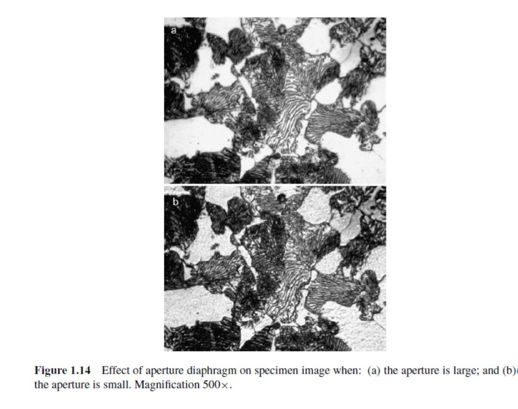
87 Steps for Optimum Resolution Use an objective lens with the highest NA possible; Use high magnification; Use an eyepiece compatible with the chosen objective lens; Use the shortest possible wavelength light; Keep the light system properly centered; Use oil immersion lenses if available; Adjust the field diaphragm for maximum contrast and the aperture diaphragm for maximum resolution and contrast; and Adjust brightness for best resolution.
88 Steps to Improve Depth of Field Reduce NA by closing the aperture diaphragm, or use an objective lens with lower NA; Lower the magnification for a given NA; Use a high-power eyepiece with a low-power, high-na objective lens; and Use the longest possible wavelength light.
89 Imaging Modes The most commonly used examination modes, bright-field and dark-field imaging, are based on contrast due to differences in wave amplitudes.

90
91 Metal (Reflected Light ) microscope

92
93

94 Generating Contrast: Polycarbonate/ polybutylene terephthalate composite Contrast by Massdensity difference
95 Imaging Modes: The differences in properties of the light waves reflected from microscopic objects enable us to observe these objects by light microscopy. The light wave changes in either amplitude or phase when it interacts with an object as illustrated in Figure The eye can only appreciate amplitude and wavelength differences in light waves, not their phase difference.
96 Imaging Modes:
97 Light
98 Imaging Modes: The most commonly used examination modes: Bright-field imaging and Dark-field imaging, are based on contrast due to differences in wave amplitudes.
99 Imaging Modes: The wave phase differences have to be converted to amplitude differences through special optical arrangements such as in the examination modes of : Phase contrast, Polarized light and Nomarski contrast.
100 Bright-Field and Dark-Field Imaging Bright-field imaging is the predominant mode for examining microstructure. Dark-field imaging is also widely used to obtain an image with higher contrast than in bright-field. Figure 1.28 illustrates the difference in optical arrangement between these modes in transmitted illumination.

101 Bright-Field Imaging: a) b) Figure 1.28 (a) Bright-field illumination; and (b) dark-field illumination in transmitted mode. Shaded areas indicate where the light is blocked. In bright-field imaging, the specimen is evenly illuminated by a light source.
102 Dark-Field Imaging Dark-field imaging requires that the specimen is illuminated by oblique light rays. There is a central stop in the light path to block the central portion of light rays from illuminating the specimen directly. Thus, the angle of the light rays illuminating the specimen is so large that light from the specimen cannot enter the objective lens unless it are scattered by microscopic objects. Oblique: angled, diagonal
103 Dark-Field Imaging in Reflected Mode The dark field in reflected illumination is also realized using a central stop in the light path (Figure 1.29), similar to that of transmitted illumination. The light rays in a ring shape will be further reflected in order to illuminate a specimen surface with an oblique angle.


104 Figure 1.30 Comparison between: (a) bright-field; and (b) dark-field images of AISI 1080 high carbon steel. In addition to grain boundaries and oxide particles, annealing twins are revealed in the dark-field image. Figure 1.30 shows the comparison between bright- and dark-field images of an identical field in a high carbon steel specimen under a reflected light microscope. Microscopic features such as grain boundaries and second phase particles appear self-luminous in the dark field image as shown in Figure 1.30.
 reflection from")
105 Figure 1.26 Contrast generated by etching grain boundaries in light microscope: (a) reflection from different parts of a surface (b) micrograph of grain boundaries which appear as dark lines.
 Dark Field")
106 Microstructure of electrolytic iron a) Bright Field Imaging b) Dark Field Imaging
107 Phase Contrast Microscopy Phase contrast is a useful technique for specimens such as polymers that have little inherent contrast in the bright-field mode. In the technique, a phase change due to light diffraction by an object is converted to an amplitude change. This conversion is based on interference phenomenon of light waves as illustrated in Figure 1.31.
108 Imaging Modes:
109 Light
110
111 Constructive interference Constructive interference occurs when combining two samewavelength waves that do not have a phase difference between them.
112 Destructive interference Destructive interference occurs when combining two waves with phase difference of a half wavelength (λ/2)
113 Polarized Light Microscopy Polarized light is used to examine specimens exhibiting optical anisotropy. Optical anisotropy arises when materials transmit or reflect light with different velocities in different directions. Most materials exhibiting optical anisotropy have a non-cubic crystal structure.
114 Light, as an electro magnetic wave, vibrates in all directions perpendicular to the direction of propagation. If light waves pass through a polarizing filter, called a polarizer, the transmitted wave will vibrate in a single plane.
115 Such light is referred to as plane polarized light. When polarized light is transmitted or reflected by anisotropic material, the polarized light vibrates in a different plane from the incident plane. Such polarization changes generate the contrast associated with anisotropic materials.
 have different mechanical, optical, magnetic or dielectric properties along different directions.")
116 Anisotropy:Materials with grains which are oriented along certain directions (naturally or deliberately obtained by processing) have different mechanical, optical, magnetic or dielectric properties along different directions.

117 Interactions between polarized light and anisotrophic object Birefringent Crystal: transparent crystal, with different refractive indices in two perpendicular directions. Figure illustrates the interaction between polarized light and an anisotropic object.
118 When a polarized light ray hits a birefringent crystal, the light ray is split into two polarized light waves (ordinary wave and extraordinary wave) vibrating in two planes perpendicular to each other.
119 Because there are two refractive indices, the two split light rays travel at different velocities (speed), and thus exhibit phase difference. These two rays, with a phase difference vibrating in two perpendicular planes, produce polarized light because the electric vectors of their waves are added.
120 If the two polarized-light waves have a phase difference of λ/4, the projection of resultant light is a spiraling circle.
121 If the two polarized-light waves have a phase difference of λ/2, the projection of resultant light is linear.
122 If the two polarized-light waves have another phase difference, the projection of resultant ray is a spiraling ellipse.
123 Analyzer Differences in the resultant light can be detected by another polarizing filter called an analyzer. Both polarizer and analyzer can only allow plane polarized light to be transmitted. The analyzer has a different orientation of polarization plane with respect to that of the polarizer.
124 Figure 1.37 illustrates the amplitude of elliptically polarized light in a two-dimensional plane and the light amplitude passing through an analyzer which is placed 90 with respect to the polarizer (called the crossed position of the polarizer and analyzer).
 bright-field image; and (b) polarized light image in which grains are")
125 Figure 1.38 Example of using polarized-light microscopy for pure titanium specimen: (a) bright-field image; and (b) polarized light image in which grains are revealed. (Reproduced from G.F. Vander Voort, Metallography Principles and Practice, McGraw-Hill, New York. N. Gendron, General Electric Co.)
126 Applications of Polarized Light Microscopy Polarized light can enhance the contrast of anisotropic materials, particularly when they are difficult to etch. The thickness of anisotropic coatings from its cross sections could be examined by polarized light. A thick oxide film on isotropic metals also makes them sensitive to the direction of polarized light because of double reflection from surface irregularities in the film.


127 Phyllite, a metamorphic rock, clearly shows the alignment of crystals under the effects of heat and stress. Polarized light microscopy could be used for identification of jeological samples and minerals.
128 Pure Aluminum Microstructure a) Bright Field b) Polarized Light

129 Titanium-bone implant interface
130 Nomarski Microscopy Nomarski microscopy is an examination mode using differential interference contrast (DIC). The images that DIC produces are deceptively three-dimensional with apparent shadows and a relief-like appearance. Nomarski microscopy also uses polarized light with the polarizer and the analyzer arranged as in the polarized light mode.


131 Nomarski Microscopy In addition, double quartz prisms; (Wollaston prisms or DIC prisms) are used to split polarized light and generate a phase difference.
132 The working principles of Nomarski microscopy can be illustrated using the light path in a transmitted light microscope as illustrated in Figure 1.40.
133 Nomarski Microscopy The first DIC prism is placed behind the polarizer and in front of the condenser lens, and the second DIC prism is placed behind the objective lens and in front of the analyzer. The two beams created by the prism interfere coherently in the image plane and produce two slightly displaced images differing in phase, thus producing height contrast.
134 Optical arrangement of Nomarski microscopy in reflected light illumination: 1 polarizer; 2, λ/4 -plate; 3 DIC prism; 4 objective lens; 5 specimen; 6 light reflector and 7 analyzer.
135 Role of the First DIC Prism The first DIC prism splits polarized light beam from the polarizer into two parallel beams traveling along different physical paths. If a specimen does not generate a path difference between the two parallel beams as shown by two left side beam pairs in Figure 1.40.
136 Role of Second DIC Prism The second DIC prism recombines the pairs and produces linearly polarized light with the same polarization plane as it was before it was split by the first DIC prism.
137 If a specimen does not generate a path difference between the two parallel, the second DIC prism recombines the pairs and produces linearly polarized light. Thus, the analyzer in the crossed position with a polarizer will block light transmission. If a specimen generates a path difference in a pair of beams, as shown by the right-side beam pair, the recombined pair produced by the second DIC prism will be elliptically polarized light. The analyzer cannot block such light and a bright area will bevisible.


138 The DIC prism is commonly integrated in the barrel of the objective lens, indicated by DIC marked on the barrel surface.

 Nomarski contrast of")
139 Nomarski Contrast Figure 1.42 Effects of Nomarski contrast on carbon steel micrographs: (a) bright field; and (b) Nomarski contrast of the same field.

140

141

142
143 Confocal Microscopy Confocal microscopy is a related new technique that provides three-dimensional (3D) optical resolution. Image formation in a confocal microscope is significantly different from a conventional light microscope. Compared with a conventional compound microscope, a modern confocal microscope has two distinctive features in its structure: a laser light source and a scanning device.
144 Confocal Microscopy Thus, the confocal microscope is often referred to as the confocal laser scanning microscope (CLSM). The laser light provides a high-intensity beam to generate image signals from individual microscopic spots in the specimen. The scanning device moves the beam in a rectangular area of specimen to construct a 3D image on a computer.
145 The optical principles of confocal microscopy can be understood by examining the CLSM optical path that has reflected illumination as illustrated in Figure Working Principles
146 Working Principles The laser beam is focused as an intense spot on a certain focal plane of the specimen by a condenser lens, which is also serves as an objective lens to collect the reflected beam. A pinhole aperture is placed at a confocal plane in front of the light detector. Only the light signals from the focal point in the specimen are recorded each time. Since the pinhole aperture can block a large amount of reflected light, high-intensity laser illumination is necessary to ensure that sufficient signals are received by the detector. The detector is commonly a photomultiplier tube (PMT) that converts light signals to electric signals for image processing in a computer.
147 Working Principles To acquire an image of the focal plane, the plane has to be scanned in its two lateral directions (x y directions). To acquire a 3D image of a specimen, the plane images at different vertical positions should also be recorded. A scanning device moves the focal laser spot in the x y directions on the plane in a regular pattern called a raster. After finishing one scanning plane, the focal spot is moved in the vertical direction to scan a next parallel plane.
148 Scanning modes: Figure 1.46 Two scanning methods in the confocal microscope: (a) specimen scanning; and (b)laser scanning.
149 Specimen Scanning Mode Figure 1.46 illustrates two different methods of scanning in CLSM: specimen and laser scanning. Specimen scanning was used in early confocal microscopes. The specimen moves with respect to the focal spot and the optical arrangement is kept stationary. The beam is always located at the optical axis in the microscope so that optical aberration is minimized. The main drawback of this method is the low scanning speed.
150
151 Laser Scanning Mode Laser scanning is realized by two scanning mirrors rotating along mutually perpendicular axes as shown in Figure 1.46b. The scan mirror can move the focal spot in the specimen by sensitively changing the reflecting angle of mirror. Changing the vertical position of the spot is still achieved by moving the specimen in the laser scanning method.
152
153 Resolution The resolution of the confocal microscope is mainly determined by the size of focal spot of the laser beam. High spatial resolution about 0.2μmcan be achieved. A 3D image of specimen with thickness of up to 200μm is also achievable, depending on the opacity of specimen.
154
155


156
157 Applications Although its major applications are in biology, confocal microscopy can also be used for examining the surface topography and internal structure of semi-transparent materials. Figure 1.48 shows an example of using confocal fluorescent microscopy to examine particulate penetration through an air filter made of polymer foam. The particulates were fluorescently labeled and their locations in the polymer foam are revealed against the polymer foam surfaces.
 highlights of")
158 Figure 1.48 Confocal micrographs of polyurethane foam with labeled particulates: (a) highlights of particulates; and (b) locations of particulates on the foam surfaces. The scale bar is 1 mm.
159 ght/index.html &v=NlTYHeLZ5co&feature=playe r_detailpage
Basics of Light Microscopy and Metallography
 ENGR45: Introduction to Materials Spring 2012 Laboratory 8 Basics of Light Microscopy and Metallography In this exercise you will: gain familiarity with the proper use of a research-grade light microscope
CHAPTER TWO METALLOGRAPHY & MICROSCOPY
 CHAPTER TWO METALLOGRAPHY & MICROSCOPY 1. INTRODUCTION: Materials characterisation has two main aspects: Accurately measuring the physical, mechanical and chemical properties of materials Accurately measuring
VISUAL PHYSICS ONLINE DEPTH STUDY: ELECTRON MICROSCOPES
 VISUAL PHYSICS ONLINE DEPTH STUDY: ELECTRON MICROSCOPES Shortly after the experimental confirmation of the wave properties of the electron, it was suggested that the electron could be used to examine objects
Very short introduction to light microscopy and digital imaging
 Very short introduction to light microscopy and digital imaging Hernan G. Garcia August 1, 2005 1 Light Microscopy Basics In this section we will briefly describe the basic principles of operation and
Observing Microorganisms through a Microscope LIGHT MICROSCOPY: This type of microscope uses visible light to observe specimens. Compound Light Micros
 PHARMACEUTICAL MICROBIOLOGY JIGAR SHAH INSTITUTE OF PHARMACY NIRMA UNIVERSITY Observing Microorganisms through a Microscope LIGHT MICROSCOPY: This type of microscope uses visible light to observe specimens.
Applications of Optics
 Nicholas J. Giordano www.cengage.com/physics/giordano Chapter 26 Applications of Optics Marilyn Akins, PhD Broome Community College Applications of Optics Many devices are based on the principles of optics
Introduction to Light Microscopy. (Image: T. Wittman, Scripps)
") Introduction to Light Microscopy (Image: T. Wittman, Scripps) The Light Microscope Four centuries of history Vibrant current development One of the most widely used research tools A. Khodjakov et al. Major
Introduction to Light Microscopy (Image: T. Wittman, Scripps) The Light Microscope Four centuries of history Vibrant current development One of the most widely used research tools A. Khodjakov et al. Major
Microscopy Techniques that make it easy to see things this small.
 Microscopy Techniques that make it easy to see things this small. What is a Microscope? An instrument for viewing objects that are too small to be seen easily by the naked eye. Dutch spectacle-makers Hans
Imaging Introduction. September 24, 2010
 Imaging Introduction September 24, 2010 What is a microscope? Merriam-Webster: an optical instrument consisting of a lens or combination of lenses for making enlarged images of minute objects; especially:
Biology 29 Cell Structure and Function Spring, 2009 Springer LABORATORY 1: THE LIGHT MICROSCOPE
 Biology 29 Cell Structure and Function Spring, 2009 Springer LABORATORY 1: THE LIGHT MICROSCOPE Prior to lab: 1) Read these instructions (p 1-6) 2) Go through the online tutorial, the microscopy pre-lab
Microscope anatomy, image formation and resolution
 Microscope anatomy, image formation and resolution Ian Dobbie Buy this book for your lab: D.B. Murphy, "Fundamentals of light microscopy and electronic imaging", ISBN 0-471-25391-X Visit these websites:
Education in Microscopy and Digital Imaging
 Contact Us Carl Zeiss Education in Microscopy and Digital Imaging ZEISS Home Products Solutions Support Online Shop ZEISS International ZEISS Campus Home Interactive Tutorials Basic Microscopy Spectral
Microscopy: Fundamental Principles and Practical Approaches
 Microscopy: Fundamental Principles and Practical Approaches Simon Atkinson Online Resource: http://micro.magnet.fsu.edu/primer/index.html Book: Murphy, D.B. Fundamentals of Light Microscopy and Electronic
GEOMETRICAL OPTICS Practical 1. Part I. BASIC ELEMENTS AND METHODS FOR CHARACTERIZATION OF OPTICAL SYSTEMS
 GEOMETRICAL OPTICS Practical 1. Part I. BASIC ELEMENTS AND METHODS FOR CHARACTERIZATION OF OPTICAL SYSTEMS Equipment and accessories: an optical bench with a scale, an incandescent lamp, matte, a set of
Reflection! Reflection and Virtual Image!
 1/30/14 Reflection - wave hits non-absorptive surface surface of a smooth water pool - incident vs. reflected wave law of reflection - concept for all electromagnetic waves - wave theory: reflected back
microscopy A great online resource Molecular Expressions, a Microscope Primer Partha Roy
 Fundamentals of optical microscopy A great online resource Molecular Expressions, a Microscope Primer http://micro.magnet.fsu.edu/primer/index.html Partha Roy 1 Why microscopy Topics Functions of a microscope
Observing Microorganisms through a Microscope
 2016/2/19 PowerPoint Lecture Presentations prepared by Bradley W. Christian, McLennan Community College CHAPTER 3 Observing Microorganisms through a Microscope 1 Figure 3.2 Microscopes and Magnification.
SUBJECT: PHYSICS. Use and Succeed.
 SUBJECT: PHYSICS I hope this collection of questions will help to test your preparation level and useful to recall the concepts in different areas of all the chapters. Use and Succeed. Navaneethakrishnan.V
ABC Math Student Copy. N. May ABC Math Student Copy. Physics Week 13(Sem. 2) Name. Light Chapter Summary Cont d 2
 Name. Light Chapter Summary Cont d 2") Page 1 of 12 Physics Week 13(Sem. 2) Name Light Chapter Summary Cont d 2 Lens Abberation Lenses can have two types of abberation, spherical and chromic. Abberation occurs when the rays forming an image
Page 1 of 12 Physics Week 13(Sem. 2) Name Light Chapter Summary Cont d 2 Lens Abberation Lenses can have two types of abberation, spherical and chromic. Abberation occurs when the rays forming an image
The Nature of Light. Light and Energy
 The Nature of Light Light and Energy - dependent on energy from the sun, directly and indirectly - solar energy intimately associated with existence of life -light absorption: dissipate as heat emitted
Indian Institute of technology Madras Presents NPTEL NATIONAL PROGRAMME ON TECHNOLOGY ENHANCED LEARNING
 Indian Institute of technology Madras Presents NPTEL NATIONAL PROGRAMME ON TECHNOLOGY ENHANCED LEARNING Lecture - 5 Materials Characterization Fundamentals of Optical microscopy Dr. S. Sankaran Associate
Chapter Ray and Wave Optics
 109 Chapter Ray and Wave Optics 1. An astronomical telescope has a large aperture to [2002] reduce spherical aberration have high resolution increase span of observation have low dispersion. 2. If two
OPTICAL SYSTEMS OBJECTIVES
 101 L7 OPTICAL SYSTEMS OBJECTIVES Aims Your aim here should be to acquire a working knowledge of the basic components of optical systems and understand their purpose, function and limitations in terms
LlIGHT REVIEW PART 2 DOWNLOAD, PRINT and submit for 100 points
 WRITE ON SCANTRON WITH NUMBER 2 PENCIL DO NOT WRITE ON THIS TEST LlIGHT REVIEW PART 2 DOWNLOAD, PRINT and submit for 100 points Multiple Choice Identify the choice that best completes the statement or
Applied Optics. , Physics Department (Room #36-401) , ,
 , ,") Applied Optics Professor, Physics Department (Room #36-401) 2290-0923, 019-539-0923, shsong@hanyang.ac.kr Office Hours Mondays 15:00-16:30, Wednesdays 15:00-16:30 TA (Ph.D. student, Room #36-415) 2290-0921,
Applied Optics Professor, Physics Department (Room #36-401) 2290-0923, 019-539-0923, shsong@hanyang.ac.kr Office Hours Mondays 15:00-16:30, Wednesdays 15:00-16:30 TA (Ph.D. student, Room #36-415) 2290-0921,
OPTICAL PRINCIPLES OF MICROSCOPY. Interuniversity Course 28 December 2003 Aryeh M. Weiss Bar Ilan University
 OPTICAL PRINCIPLES OF MICROSCOPY Interuniversity Course 28 December 2003 Aryeh M. Weiss Bar Ilan University FOREWORD This slide set was originally presented at the ISM Workshop on Theoretical and Experimental
Resolution. Diffraction from apertures limits resolution. Rayleigh criterion θ Rayleigh = 1.22 λ/d 1 peak at 2 nd minimum. θ f D
 Microscopy Outline 1. Resolution and Simple Optical Microscope 2. Contrast enhancement: Dark field, Fluorescence (Chelsea & Peter), Phase Contrast, DIC 3. Newer Methods: Scanning Tunneling microscopy (STM),
Light Microscopy. Upon completion of this lecture, the student should be able to:
 Light Light microscopy is based on the interaction of light and tissue components and can be used to study tissue features. Upon completion of this lecture, the student should be able to: 1- Explain the
INTRODUCTION THIN LENSES. Introduction. given by the paraxial refraction equation derived last lecture: Thin lenses (19.1) = 1. Double-lens systems
 = 1. Double-lens systems") Chapter 9 OPTICAL INSTRUMENTS Introduction Thin lenses Double-lens systems Aberrations Camera Human eye Compound microscope Summary INTRODUCTION Knowledge of geometrical optics, diffraction and interference,
Chapter 9 OPTICAL INSTRUMENTS Introduction Thin lenses Double-lens systems Aberrations Camera Human eye Compound microscope Summary INTRODUCTION Knowledge of geometrical optics, diffraction and interference,
Lecture 23 MNS 102: Techniques for Materials and Nano Sciences
 Lecture 23 MNS 102: Techniques for Materials and Nano Sciences Reference: #1 C. R. Brundle, C. A. Evans, S. Wilson, "Encyclopedia of Materials Characterization", Butterworth-Heinemann, Toronto (1992),
CCAM Microscope Objectives
 CCAM Microscope Objectives Things to consider when selecting an objective Magnification Numerical Aperture (NA) resolving power and light intensity of the objective Working Distance distance between the
Chapter 23 Study Questions Name: Class:
 Chapter 23 Study Questions Name: Class: Multiple Choice Identify the letter of the choice that best completes the statement or answers the question. 1. When you look at yourself in a plane mirror, you
BASICS IN BIOIMAGING AND OPTICS PLATFORM EPFL SV PTBIOP LIGHT MICROSCOPY
 BASICS IN LIGHT MICROSCOPY OVERVIEW 1. Motivation 2. Basic in optics 3. How microscope works 4. Illumination and resolution 5. Microscope optics 6. Contrasting methods -2- MOTIVATION Why do we need microscopy?
Microscopy. Matti Hotokka Department of Physical Chemistry Åbo Akademi University
 Microscopy Matti Hotokka Department of Physical Chemistry Åbo Akademi University What s coming Anatomy of a microscope Modes of illumination Practicalities Special applications Basic microscope Ocular
Performance Factors. Technical Assistance. Fundamental Optics
 Performance Factors After paraxial formulas have been used to select values for component focal length(s) and diameter(s), the final step is to select actual lenses. As in any engineering problem, this
Chapter 16 Light Waves and Color
 Chapter 16 Light Waves and Color Lecture PowerPoint Copyright The McGraw-Hill Companies, Inc. Permission required for reproduction or display. What causes color? What causes reflection? What causes color?
Transmission electron Microscopy
 Transmission electron Microscopy Image formation of a concave lens in geometrical optics Some basic features of the transmission electron microscope (TEM) can be understood from by analogy with the operation
Name. Light Chapter Summary Cont d. Refraction
 Page 1 of 17 Physics Week 12(Sem. 2) Name Light Chapter Summary Cont d with a smaller index of refraction to a material with a larger index of refraction, the light refracts towards the normal line. Also,
25 cm. 60 cm. 50 cm. 40 cm.
 Geometrical Optics 7. The image formed by a plane mirror is: (a) Real. (b) Virtual. (c) Erect and of equal size. (d) Laterally inverted. (e) B, c, and d. (f) A, b and c. 8. A real image is that: (a) Which
30 Lenses. Lenses change the paths of light.
 Lenses change the paths of light. A light ray bends as it enters glass and bends again as it leaves. Light passing through glass of a certain shape can form an image that appears larger, smaller, closer,
COURSE NAME: PHOTOGRAPHY AND AUDIO VISUAL PRODUCTION (VOCATIONAL) FOR UNDER GRADUATE (FIRST YEAR)
 FOR UNDER GRADUATE (FIRST YEAR)") COURSE NAME: PHOTOGRAPHY AND AUDIO VISUAL PRODUCTION (VOCATIONAL) FOR UNDER GRADUATE (FIRST YEAR) PAPER TITLE: BASIC PHOTOGRAPHIC UNIT - 3 : SIMPLE LENS TOPIC: LENS PROPERTIES AND DEFECTS OBJECTIVES By
COURSE NAME: PHOTOGRAPHY AND AUDIO VISUAL PRODUCTION (VOCATIONAL) FOR UNDER GRADUATE (FIRST YEAR) PAPER TITLE: BASIC PHOTOGRAPHIC UNIT - 3 : SIMPLE LENS TOPIC: LENS PROPERTIES AND DEFECTS OBJECTIVES By
CCAM s Selection of. Zeiss Microscope Objectives
 CCAM s Selection of Zeiss Microscope Objectives 1. Magnification Image scale 2. Resolution The minimum separation distance between two points that are clearly resolved. The resolution of an objective is
Optical Microscopy and Imaging ( Part 2 )
") 1 Optical Microscopy and Imaging ( Part 2 ) Chapter 7.1 : Semiconductor Science by Tudor E. Jenkins Saroj Kumar Patra, Department of Electronics and Telecommunication, Norwegian University of Science and
1 Optical Microscopy and Imaging ( Part 2 ) Chapter 7.1 : Semiconductor Science by Tudor E. Jenkins Saroj Kumar Patra, Department of Electronics and Telecommunication, Norwegian University of Science and
Chapter 25. Optical Instruments
 Chapter 25 Optical Instruments Optical Instruments Analysis generally involves the laws of reflection and refraction Analysis uses the procedures of geometric optics To explain certain phenomena, the wave
Chapter 1 Parts. Figure 1.1. Parts of a Compound Light Microscope
 Chapter 1 Parts Chapter 1 Parts Figure 1.1 illustrates the parts of an upright compound microscope and indicates the terminology that I use in these notes. Figure 1.1. Parts of a Compound Light Microscope
LOS 1 LASER OPTICS SET
 LOS 1 LASER OPTICS SET Contents 1 Introduction 3 2 Light interference 5 2.1 Light interference on a thin glass plate 6 2.2 Michelson s interferometer 7 3 Light diffraction 13 3.1 Light diffraction on a
PHYSICS. Chapter 35 Lecture FOR SCIENTISTS AND ENGINEERS A STRATEGIC APPROACH 4/E RANDALL D. KNIGHT
 PHYSICS FOR SCIENTISTS AND ENGINEERS A STRATEGIC APPROACH 4/E Chapter 35 Lecture RANDALL D. KNIGHT Chapter 35 Optical Instruments IN THIS CHAPTER, you will learn about some common optical instruments and
2. The reflected-light microscopy, description and function of a reflected-light microscope
 2. The reflected-light microscopy, description and function of a reflected-light microscope 2.1. The reflected-light microscopy 2.2. The appearance of polished sections under the reflected-light microscope
Chapter 1. Basic Electron Optics (Lecture 2)
") Chapter 1. Basic Electron Optics (Lecture 2) Basic concepts of microscope (Cont ) Fundamental properties of electrons Electron Scattering Instrumentation Basic conceptions of microscope (Cont ) Ray diagram
Chapter 1. Basic Electron Optics (Lecture 2) Basic concepts of microscope (Cont ) Fundamental properties of electrons Electron Scattering Instrumentation Basic conceptions of microscope (Cont ) Ray diagram
NanoSpective, Inc Progress Drive Suite 137 Orlando, Florida
 TEM Techniques Summary The TEM is an analytical instrument in which a thin membrane (typically < 100nm) is placed in the path of an energetic and highly coherent beam of electrons. Typical operating voltages
GIST OF THE UNIT BASED ON DIFFERENT CONCEPTS IN THE UNIT (BRIEFLY AS POINT WISE). RAY OPTICS
. RAY OPTICS") 209 GIST OF THE UNIT BASED ON DIFFERENT CONCEPTS IN THE UNIT (BRIEFLY AS POINT WISE). RAY OPTICS Reflection of light: - The bouncing of light back into the same medium from a surface is called reflection
209 GIST OF THE UNIT BASED ON DIFFERENT CONCEPTS IN THE UNIT (BRIEFLY AS POINT WISE). RAY OPTICS Reflection of light: - The bouncing of light back into the same medium from a surface is called reflection
PHYSICS FOR THE IB DIPLOMA CAMBRIDGE UNIVERSITY PRESS
 Option C Imaging C Introduction to imaging Learning objectives In this section we discuss the formation of images by lenses and mirrors. We will learn how to construct images graphically as well as algebraically.
Fabrication of Probes for High Resolution Optical Microscopy
 Fabrication of Probes for High Resolution Optical Microscopy Physics 564 Applied Optics Professor Andrès La Rosa David Logan May 27, 2010 Abstract Near Field Scanning Optical Microscopy (NSOM) is a technique
Instruction Manual T Binocular Acromat Research Scope T Trinocular Acromat Research Scope
 Research Scope Instruction Manual T-29031 Binocular Acromat Research Scope T-29041 Trinocular Acromat Research Scope T-29032 Binocular Semi-Plan Research Scope T-29042 Trinocular Semi-Plan Research Scope
End-of-Chapter Exercises
 End-of-Chapter Exercises Exercises 1 12 are conceptual questions designed to see whether you understand the main concepts in the chapter. 1. Red laser light shines on a double slit, creating a pattern
Unit 8: Light and Optics
 Objectives Unit 8: Light and Optics Explain why we see colors as combinations of three primary colors. Explain the dispersion of light by a prism. Understand how lenses and mirrors work. Explain thermal
The diffraction of light
 7 The diffraction of light 7.1 Introduction As introduced in Chapter 6, the reciprocal lattice is the basis upon which the geometry of X-ray and electron diffraction patterns can be most easily understood
Systems Biology. Optical Train, Köhler Illumination
 McGill University Life Sciences Complex Imaging Facility Systems Biology Microscopy Workshop Tuesday December 7 th, 2010 Simple Lenses, Transmitted Light Optical Train, Köhler Illumination What Does a
Chapters 1 & 2. Definitions and applications Conceptual basis of photogrammetric processing
 Chapters 1 & 2 Chapter 1: Photogrammetry Definitions and applications Conceptual basis of photogrammetric processing Transition from two-dimensional imagery to three-dimensional information Automation
S200 Course LECTURE 1 TEM
 S200 Course LECTURE 1 TEM Development of Electron Microscopy 1897 Discovery of the electron (J.J. Thompson) 1924 Particle and wave theory (L. de Broglie) 1926 Electromagnetic Lens (H. Busch) 1932 Construction
Average: Standard Deviation: Max: 99 Min: 40
 1 st Midterm Exam Average: 83.1 Standard Deviation: 12.0 Max: 99 Min: 40 Please contact me to fix an appointment, if you took less than 65. Chapter 33 Lenses and Op/cal Instruments Units of Chapter 33
Köhler Illumination: A simple interpretation
 Köhler Illumination: A simple interpretation 1 Ref: Proceedings of the Royal Microscopical Society, October 1983, vol. 28/4:189-192 PETER EVENNETT Department of Pure & Applied Biology, The University of
Test Review # 8. Physics R: Form TR8.17A. Primary colors of light
 Physics R: Form TR8.17A TEST 8 REVIEW Name Date Period Test Review # 8 Light and Color. Color comes from light, an electromagnetic wave that travels in straight lines in all directions from a light source
Section 1: Sound. Sound and Light Section 1
 Sound and Light Section 1 Section 1: Sound Preview Key Ideas Bellringer Properties of Sound Sound Intensity and Decibel Level Musical Instruments Hearing and the Ear The Ear Ultrasound and Sonar Sound
 Microscopy http://www.microscopyu.com/articles/phasecontrast/phasemicroscopy.html http://micro.magnet.fsu.edu/primer/anatomy/anatomy.html 2005, Dr. Jack Ikeda & Dr. Gail Grabner 9 Nikon Labophot (Question
Phys214 Fall 2004 Midterm Form A
 1. A clear sheet of polaroid is placed on top of a similar sheet so that their polarizing axes make an angle of 30 with each other. The ratio of the intensity of emerging light to incident unpolarized
WHS-CH-23 Light: Geometric Optics Show all your work, equations used, and box in your answers!
 WHS-CH-23 Light: Geometric Optics Show all your work, equations used, and box in your answers! Willebrord Snell (1591-1626) Snell developed methods for measuring the Earth. He proposed the method of triangulation
General Physics II. Ray Optics
 General Physics II Ray Optics 1 Dispersion White light is a combination of all the wavelengths of the visible part of the electromagnetic spectrum. Red light has the longest wavelengths and violet light
ECEN 4606, UNDERGRADUATE OPTICS LAB
 ECEN 4606, UNDERGRADUATE OPTICS LAB Lab 2: Imaging 1 the Telescope Original Version: Prof. McLeod SUMMARY: In this lab you will become familiar with the use of one or more lenses to create images of distant
Optical design of a high resolution vision lens
 Optical design of a high resolution vision lens Paul Claassen, optical designer, paul.claassen@sioux.eu Marnix Tas, optical specialist, marnix.tas@sioux.eu Prof L.Beckmann, l.beckmann@hccnet.nl Summary:
FRAUNHOFER AND FRESNEL DIFFRACTION IN ONE DIMENSION
 FRAUNHOFER AND FRESNEL DIFFRACTION IN ONE DIMENSION Revised November 15, 2017 INTRODUCTION The simplest and most commonly described examples of diffraction and interference from two-dimensional apertures
Chapter 18 Optical Elements
 Chapter 18 Optical Elements GOALS When you have mastered the content of this chapter, you will be able to achieve the following goals: Definitions Define each of the following terms and use it in an operational
Katarina Logg, Kristofer Bodvard, Mikael Käll. Dept. of Applied Physics. 12 September Optical Microscopy. Supervisor s signature:...
 Katarina Logg, Kristofer Bodvard, Mikael Käll Dept. of Applied Physics 12 September 2007 O1 Optical Microscopy Name:.. Date:... Supervisor s signature:... Introduction Over the past decades, the number
Week IV: FIRST EXPERIMENTS WITH THE ADVANCED OPTICS SET
 Week IV: FIRST EXPERIMENTS WITH THE ADVANCED OPTICS SET The Advanced Optics set consists of (A) Incandescent Lamp (B) Laser (C) Optical Bench (with magnetic surface and metric scale) (D) Component Carriers
attocfm I for Surface Quality Inspection NANOSCOPY APPLICATION NOTE M01 RELATED PRODUCTS G
 APPLICATION NOTE M01 attocfm I for Surface Quality Inspection Confocal microscopes work by scanning a tiny light spot on a sample and by measuring the scattered light in the illuminated volume. First,
Script Bio 407 Applied Microscopy Light microscopy
 Center for Microscopy and Image Analysis Dr. José María Mateos Center for Microscopy and Image Analysis Winterthurerstrasse 190 CH-8057 Zurich Phone 044 635 98 20 mateos@zmb.uzh.ch www.zmb.uzh.ch Script
Chapter 29/30. Wave Fronts and Rays. Refraction of Sound. Dispersion in a Prism. Index of Refraction. Refraction and Lenses
 Chapter 29/30 Refraction and Lenses Refraction Refraction the bending of waves as they pass from one medium into another. Caused by a change in the average speed of light. Analogy A car that drives off
OPELCO OPtical ELements COrporation LB Objective Series for Biological Use
 LB Objective Series for Biological Use 105 Executive Drive Suite 100 Dulles, VA 20166-9558 Tel: (703) 471-0080 S PLAN APOCHROMAT OBJECTIVES These objectives compensate for three wavelength of chromatic
IMAGE SENSOR SOLUTIONS. KAC-96-1/5" Lens Kit. KODAK KAC-96-1/5" Lens Kit. for use with the KODAK CMOS Image Sensors. November 2004 Revision 2
 KODAK for use with the KODAK CMOS Image Sensors November 2004 Revision 2 1.1 Introduction Choosing the right lens is a critical aspect of designing an imaging system. Typically the trade off between image
REFRACTION OF LIGHT VERY SHORT ANSWER QUESTIONS
 REFRACTION OF LIGHT VERY SHORT ANSWER QUESTIONS Q-1. The earth takes 24 h to rotate once about its axis. How much time does the sun take to shift by 1 0 when viewed from the earth? Q-2. What is the maximum
R.B.V.R.R. WOMEN S COLLEGE (AUTONOMOUS) Narayanaguda, Hyderabad.
 Narayanaguda, Hyderabad.") R.B.V.R.R. WOMEN S COLLEGE (AUTONOMOUS) Narayanaguda, Hyderabad. DEPARTMENT OF PHYSICS QUESTION BANK FOR SEMESTER III PAPER III OPTICS UNIT I: 1. MATRIX METHODS IN PARAXIAL OPTICS 2. ABERATIONS UNIT II
R.B.V.R.R. WOMEN S COLLEGE (AUTONOMOUS) Narayanaguda, Hyderabad. DEPARTMENT OF PHYSICS QUESTION BANK FOR SEMESTER III PAPER III OPTICS UNIT I: 1. MATRIX METHODS IN PARAXIAL OPTICS 2. ABERATIONS UNIT II
Microscopy Training & Overview
 Microscopy Training & Overview Product Marketing October 2011 Stephan Briggs - PLE OVERVIEW AND PRESENTATION FLOW Glossary and Important Terms Introduction Timeline Innovation and Advancement Primary Components
PRINCIPLE PROCEDURE ACTIVITY. AIM To observe diffraction of light due to a thin slit.
 ACTIVITY 12 AIM To observe diffraction of light due to a thin slit. APPARATUS AND MATERIAL REQUIRED Two razor blades, one adhesive tape/cello-tape, source of light (electric bulb/ laser pencil), a piece
CALIBRATION OF MICROSCOPE EYEPIECE GRATICULE
 CALIBRATION OF MICROSCOPE EYEPIECE GRATICULE A typical eyepiece graticule looks like this: It is 10mm in length and each mm is divided into 10 parts So each small division = 0.1mm = 100µm The eyepiece
Physics Test Review Reflection/Refraction/Diffraction & Lenses Session: Name:
 Multiple Choice 1. The law of reflection says that a. the angle of reflection from a mirror equals the angle of incidence. b. waves incident on a mirror are partially reflected. c. all waves incident on
MICROSCOPE LAB. Resolving Power How well specimen detail is preserved during the magnifying process.
 AP BIOLOGY Cells ACTIVITY #2 MICROSCOPE LAB OBJECTIVES 1. Demonstrate proper care and use of a compound microscope. 2. Identify the parts of the microscope and describe the function of each part. 3. Compare
06SurfaceQuality.nb Optics James C. Wyant (2012) 1
 1") 06SurfaceQuality.nb Optics 513 - James C. Wyant (2012) 1 Surface Quality SQ-1 a) How is surface profile data obtained using the FECO interferometer? Your explanation should include diagrams with the appropriate
06SurfaceQuality.nb Optics 513 - James C. Wyant (2012) 1 Surface Quality SQ-1 a) How is surface profile data obtained using the FECO interferometer? Your explanation should include diagrams with the appropriate
Aberrations of a lens
 Aberrations of a lens 1. What are aberrations? A lens made of a uniform glass with spherical surfaces cannot form perfect images. Spherical aberration is a prominent image defect for a point source on
OPTICS GLOSSARY A BRIEF EXPLANATION OF CERTAIN OPTICAL TERMS PRE1305 OPTICAL MEASURING
 OPTICS GLOSSARY A BRIEF EXPLANATION OF CERTAIN OPTICAL TERMS OPTICAL MEASURING PRE1305 INTRODUCTION INTRODUCTION With seven decades of experience and more than 5,000 specialized products, Mitutoyo is
Point Spread Function. Confocal Laser Scanning Microscopy. Confocal Aperture. Optical aberrations. Alternative Scanning Microscopy
 Bi177 Lecture 5 Adding the Third Dimension Wide-field Imaging Point Spread Function Deconvolution Confocal Laser Scanning Microscopy Confocal Aperture Optical aberrations Alternative Scanning Microscopy
Image Formation. Light from distant things. Geometrical optics. Pinhole camera. Chapter 36
 Light from distant things Chapter 36 We learn about a distant thing from the light it generates or redirects. The lenses in our eyes create images of objects our brains can process. This chapter concerns
OPAC 202 Optical Design and Instrumentation. Topic 3 Review Of Geometrical and Wave Optics. Department of
 OPAC 202 Optical Design and Instrumentation Topic 3 Review Of Geometrical and Wave Optics Department of http://www.gantep.edu.tr/~bingul/opac202 Optical & Acustical Engineering Gaziantep University Feb
INTRODUCTION TO OPTICAL MICROSCOPY
 Experimental Biophysics TEK265, FYST23, TNF060, FAF010F Lab Exercise Supervisor: Karl Adolfsson Written by Peter Jönsson and Jason Beech Updated by Henrik Persson, Karl Adolfsson and Zhen Li karl.adolfsson@ftf.lth.se
INDEX OF REFRACTION index of refraction n = c/v material index of refraction n
 INDEX OF REFRACTION The index of refraction (n) of a material is the ratio of the speed of light in vacuuo (c) to the speed of light in the material (v). n = c/v Indices of refraction for any materials
2/4/15. Brightfield Microscopy! It s all about Magnification..! or is it?!
 Brightfield Microscopy It s all about Magnification.. or is it? 1 What actually does go into chosing a microscope Choice depends on what you need the microscope to do. Do you want to magnify stained specimens?
Chapter 36. Image Formation
 Chapter 36 Image Formation Image of Formation Images can result when light rays encounter flat or curved surfaces between two media. Images can be formed either by reflection or refraction due to these
HOLIDAY HOME WORK PHYSICS CLASS-12B AUTUMN BREAK 2018
 HOLIDAY HOME WK PHYSICS CLASS-12B AUTUMN BREAK 2018 NOTE: 1. THESE QUESTIONS ARE FROM PREVIOUS YEAR BOARD PAPERS FROM 2009-2018 CHAPTERS EMI,AC,OPTICS(BUT TRY TO SOLVE ONLY NON-REPEATED QUESTION) QUESTION
NANO 703-Notes. Chapter 9-The Instrument
 1 Chapter 9-The Instrument Illumination (condenser) system Before (above) the sample, the purpose of electron lenses is to form the beam/probe that will illuminate the sample. Our electron source is macroscopic
Section A Conceptual and application type questions. 1 Which is more observable diffraction of light or sound? Justify. (1)
") INDIAN SCHOOL MUSCAT Department of Physics Class : XII Physics Worksheet - 6 (2017-2018) Chapter 9 and 10 : Ray Optics and wave Optics Section A Conceptual and application type questions 1 Which is more
INDIAN SCHOOL MUSCAT Department of Physics Class : XII Physics Worksheet - 6 (2017-2018) Chapter 9 and 10 : Ray Optics and wave Optics Section A Conceptual and application type questions 1 Which is more
Motorized Axio Observer Start-up instructions
 Start-up instructions 1. If using fluorescence turn on Fluorescent light source. TL light Source (Hal 100) 2. Turn on microscope using switch on lower left side of the microscope. 3. If imaging, turn on