Systems Biology. Optical Train, Köhler Illumination
|
|
|
- Rosa Watts
- 5 years ago
- Views:
Transcription
1 McGill University Life Sciences Complex Imaging Facility Systems Biology Microscopy Workshop Tuesday December 7 th, 2010 Simple Lenses, Transmitted Light Optical Train, Köhler Illumination
2 What Does a Microscope Need To Do? Three things need to be accomplished: 1. M A G N I F Y Produce a magnified image of the specimen. 2. C O N T R A S T Render the details within the specimen visible to the imaging device: e.g. eye, camera, photomultiplier tube 3. R E S O L V E Distinguish between objects or features within the specimen. All three things need to be accomplished.
3 Magnification and Contrast but Low Resolution
4 Magnification and Resolution but Low Contrast
5 Contrast and Resolution - but Low Magnification
6 Magnification, Contrast, Resolution


7 Magnification Magnify: Produce a magnified image of the specimen. Magnification = Mag. Objective lens x Mag. Eyepiece Lens 20x lens X 10x eyepiece = 200x magnification 60x lens X 10x eyepiece = 600x magnification 7d/fe cbcd585a2307b6ab0.jpeg GalleryPrints/Display/GP2129.jpg
8 Simple Biconvex Lens Modified by Aleks Spurmanis from
9 Simple Biconvex Lens Focal Points: Rear Focal Point (F ): Point where light coming from an infinite it distance is focused to a fine point. Modified by Aleks Spurmanis from
10 Simple Biconvex Lens Focal Points: Rear Focal Point (F ): Point where light coming from an infinite it distance is focused to a fine point. Front Focal Point (F ): Point where light rays collected from a single point source spread out into parallel l rays. Modified by Aleks Spurmanis from
11 Simple Biconvex Lens Focal Points: Rear Focal Point (F ): Point where light coming from an infinite it distance is focused to a fine point. Front Focal Point (F): Point where light rays collected from a single point source spread out into parallel l rays. Optical Axis: Imaginary line through center of lens and focal points. Modified by Aleks Spurmanis from
12 Simple Biconvex Lens Focal Points: Rear Focal Point (F ): Point where light coming from an infinite it distance is focused to a fine point. Front Focal Point (F ): Point where light rays collected from a single point source spread out into parallel l rays. Optical Axis: Imaginary line through center of lens and focal points. Focal Length: Distance along the optical axis between the center of the lens and either focal point. Modified by Aleks Spurmanis from
13 Simple Biconvex Lens Focal Planes (f and f ): planes that are one focal length away from either side of the lens. Modified by Aleks Spurmanis from
14 Simple Biconvex Lens Focal Planes (f and f ): planes that are one focal length away from either side of the lens. 2F Points: points along the optical axis that lie at 2x the focal length. Modified by Aleks Spurmanis from
15 Simple Biconvex Lens Focal Planes (f and f ): planes that are one focal length away from either side of the lens. 2F Points: points along the optical axis that lie at 2x the focal length. 2f Planes: Planes that are 2 focal lengths away from either side of the lens. Modified by Aleks Spurmanis from
16 Simple Biconvex Lens If an object is at 2F in front of the lens then an intermediate image is formed at 2F behind the lens and it is a real image. This image is formed at the intermediate image plane. Real Images: 1. Need to cross through a focal point 2. Are inverted 3. Can be projected onto a surface, captured on film or a digital detector. Modified by Aleks Spurmanis from Intermediate Image Intermediate Image Plane
17 Simple Biconvex Lens When an object is an infinite distance from the lens, a tiny real image is formed at the rear focal point (F ). Used in portrait photography. Modified by Aleks Spurmanis from
18 Magnification and Lenses Object at Infinity Scenic Photography Ray Diagram Real image formed at focal plane. Focal Point
19 Simple Biconvex Lens When an object is moved closer to 2F, the real image forms at the intermediate image plane behind F. The image is smaller than the object. Typically used in photography. Modified by Aleks Spurmanis from
20 Simple Biconvex Lens When the object lies in the 2F Plane, the real image is formed at the 2F Plane behind the lens. The object and the image are the same size. Modified by Aleks Spurmanis from
21 Simple Biconvex Lens When the object lies between F and 2F, the real image is formed behind 2F. The image is larger than the object. Used for image and film projection. Modified by Aleks Spurmanis from
22 Simple Biconvex Lens What happens when the object is placed at the front focal plane? Modified by Aleks Spurmanis from
23 Simple Biconvex Lens What happens when the object is placed at the front focal plane? No real image can be formed behind the lens since light rays from every point in the object plane leave the lens in parallel. Modified by Aleks Spurmanis from
24 Magnification and Lenses Ray Diagram No Image Formed Object at the front focal plane Front Focal Point Infinity Space
25 Simple Biconvex Lens What happens when the object is placed closer than the focal point? A virtual image is perceived behind the object when looking through the lens. Virtual Images: 1. Image is upright 2. Image can t be projected onto a surface, film or digital detectors. 3. Image appears on same side of the lens as the object. Modified by Aleks Spurmanis from
26 Magnifying Glass or a Mirror
27 Two Lens Systems Modern microscopes use a two lens system with the objective lens being one and the tube lens being the second.


28 Finite vs Infinity Corrected Optics Davidson M.W and Abramowitz M., Optical Microscopy, review article, Olympus America Inc.


29 Infinity Corrected Optics 1. Can add in additional optics between the objective lens and the tube lens. 2. Can focus by moving the objective and not the specimen (stage). 3. Eliminate i "ghost images" that t can be caused by reflections from the surfaces of lenses in finite systems.
30 Abbe s Theory of Image Formation Ernst Karl Abbe ( ) A German physicist who created the first mathematical formulation for microscope design. Prior to his work microscopes components and design was done primarily by trial and error. He worked with Carl Zeiss to develop early scientific research microscopes. He derived the formula for the theoretical resolution of the microscope. Depends on the wavelength of light, numerical aperture of the lens, refractive index of the imaging medium.
31 Interference & Diffraction Patterns Destructive Interference Slit or aperture No Interference. Modified by Claire Brown, McGill Imaging Facility using Constructive Interference
32 Interference & Diffraction Patterns Destructive Interference 1 st order Defracted Constructive Interference Zero Order not Defracted 2 nd order Defracted Constructive Interference
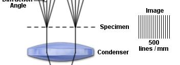
33 Imaging a Line Grating Diffraction pattern depends ds on colour ou of light. Larger spacing with longer wavelength. Red light is diffracted more than blue light
34 White Light Diffraction See a spectrum of light when white light is diffracted by a grid pattern. Blue less diffraction than red. Higher order diffraction is due to smaller features in the image. Smaller features cause a bigger difference in the amount of diffraction between the different colours. Increasing Diffraction
35 Imaging a Line Grating Diffraction Pattern depends on line spacing. Closer lines are together more diffraction. Diffraction Grating Tutorial


36 Imaging a Line Grating Diffraction Pattern depends on line spacing. Closer lines are together more diffraction. Diffraction Paths Tutorial
37 Imaging a Line Grating No Grating 10x Lens 40x Lens 60x Lens Diffraction seen at the back aperture of the objective lens.
38 Imaging Complex Patterns Vertical Lines Horizontal Lines Complex Patterns Tutorial
39 Complex Diffraction Patterns Interference: Addition of two or more waves resulting in a new wave form. Interference of two circular waves Increasing Wavelength Interference Simulation Increasing distance between wave centers.


40 Microscope Image Diffraction patterns from light interacting with all aspect of the specimen. Claire Brown, McGill Imaging Facility Large Features Small Features Random Features Ordered Features
41 Upright Microscope Illumination system below the specimen Objective lenses above the specimen Fixed location of objectives stage moves. Good for tissue or small organism imaging with water dipping lenses.
42 Upright Transmitted Light Pathway Optical Train 1) Light from the halogen lamp is focused by collector lenses and sent to the condenser.
43 Upright Transmitted Light Pathway Optical Train 1) Light from the halogen lamp is focused by collector lenses and sent to the condenser. 2) Diffusers and filters are in the light path to ensure even illumination of the field of view and to select or block certain wavelengths of light.
44 Upright Transmitted Light Pathway Optical Train 1) Light from the halogen lamp is focused by collector lenses and sent to the condenser. 2) Diffusers and filters are in the light path to ensure even illumination of the field of view and to select or block certain wavelengths of light. 3) The field diaphragm is used to select only the central portion of light from the lamp and to collimate the light.
45 Upright Transmitted Light Pathway Optical Train 4) The condenser is attached to the microscope by the condenser carrier it provides focused even illumination across the field of view for a wide range of magnifications.
46 Upright Transmitted Light Pathway Optical Train 4) The condenser is attached to the microscope by the condenser carrier it provides focused even illumination across the field of view for a wide range of magnifications. 5) The specimen is placed on the microscope stage.
47 Upright Transmitted Light Pathway Optical Train 4) The condenser is attached to the microscope by the condenser carrier it provides focused even illumination across the field of view for a wide range of magnifications. 5) The specimen is placed on the microscope stage. 6) The objective lenses are held in place by the nosepiece which can be turned putting different lenses in place.
48 Upright Transmitted Light Pathway Optical Train 7) The eyepieces (10x) magnify a virtual it limage of fthe sample that t generates a real image on the detector.
49 Upright Transmitted Light Pathway Optical Train 7) The eyepieces (10x) magnify a virtual it limage of fthe sample that t generates a real image on the detector. 8) The light can be redirected with a beam splitter to a detector, such as a CCD camera.


50 Inverted Transmitted Light Pathway Illumination system above the specimen. Objective lenses below the specimen. Fixed location of stage and objectives move. Good for living cells that need environmental control. Modified by Aleks Spurmanis from
51 Inverted Microscope Optical Train 1) Light from the halogen lamp is focused by collector lenses and sent to the condenser. Modified by Aleks Spurmanis from
52 Inverted Microscope Optical Train 1) Light from the halogen lamp is focused by collector lenses and sent to the condenser. 2) Diffusers and filters are in the light path to ensure even illumination of the field of view and to select or block certain wavelengths of light. 3) The field diaphragm is used to select only the central portion of light from the lamp and to collimate the light. Modified by Aleks Spurmanis from
53 Inverted Microscope Optical Train 4) The condenser is attached to the microscope by the condenser carrier it provides focused even illumination across the field of view for a wide range of magnifications. Modified by Aleks Spurmanis from
 The specimen is placed on the microscope stage. 6) The objective lenses are held in place by the nosepiece which can be turned putting different lenses in place.")
54 Inverted Microscope Optical Train 4) The condenser is attached to the microscope by the condenser carrier it provides focused even illumination across the field of view for a wide range of magnifications. 5) The specimen is placed on the microscope stage. 6) The objective lenses are held in place by the nosepiece which can be turned putting different lenses in place. Modified by Aleks Spurmanis from
55 Inverted Microscope Optical Train 7) The eyepieces (10x) magnify a virtual image of the sample that generates a real image on the detector. Modified by Aleks Spurmanis from
 The light can be redirected with a beam splitter to a detector, such as a CCD camera. Modified by Aleks Spurmanis from http://zeiss-campus.magnet.fsu.")
56 Inverted Microscope Optical Train 7) The eyepieces (10x) magnify a virtual image of the sample that generates a real image on the detector. 8) The light can be redirected with a beam splitter to a detector, such as a CCD camera. Modified by Aleks Spurmanis from
 The light can be redirected with a beam splitter to a detector, such as a CCD camera. 9) Camera front port. Modified by Aleks Spurmanis from http://zeiss-campus.magnet.fsu.")
57 Inverted Microscope Optical Train 7) The eyepieces (10x) magnify a virtual image of the sample that generates a real image on the detector. 8) The light can be redirected with a beam splitter to a detector, such as a CCD camera. 9) Camera front port. Modified by Aleks Spurmanis from
 The light can be redirected with a beam splitter to a detector, such as a CCD camera. 9) Camera front port. 10) Camera side port.")
58 Inverted Microscope Optical Train 7) The eyepieces (10x) magnify a virtual image of the sample that generates a real image on the detector. 8) The light can be redirected with a beam splitter to a detector, such as a CCD camera. 9) Camera front port. 10) Camera side port. Tutorial Modified by Aleks Spurmanis from
59 Köhler Illumination August Köhler ( ): A German professor who first described d a new way to illuminate microscope samples in He later went on to work for Carl Zeiss in Germany as a Physicist for 45 years. Köhler Illumination: Used to create even illumination over the specimen field of view without having an image of the light source in the field of view.
60 Conjugate Image Planes Conjugate Image Planes: A set of image planes that are optically linked and whose images are superimposed. A collector lens focuses the light source at the back focal plane of the objective putting the front focal plane of the condenser and the filament image in conjugate planes. Therefore, the filament image is no longer conjugate to the image plane, and is no longer visible.
61 Conjugate IMAGE Planes Conjugate Image Planes: There are four IMAGE planes throughout h t the optical train of the microscope that are all simultaneously in focus. 4. Retina/Detector 3. Intermediate Image 2. Specimen Plane 1. Field Stop Diaphragm Claire Brown, McGill Imaging Facility Eye Iris Diaphragm Eyepiece Lens Back Aperture of Eyepiece Back FP of Objective Objective Lens Stage Condenser Lens Front FP of Condenser Collector Lens Lamp
62 Simple Biconvex Lens Focal Planes (f and f ): planes that are one focal length away from either side of the lens. Modified by Aleks Spurmanis from
63 Conjugate IMAGE Planes
64 Conjugate APERTURE Planes Conjugate Aperture Planes: There are four aperture planes throughout the optical train of the microscope that are all simultaneously in focus. 4. Pupil of the Eye Eye Back Aperture of Eyepiece 3. Back FP of Objective 2. Front FP of Condenser Back FP of Objective Objective Lens Stage Condenser Lens Front FP of Condenser 1. Lamp Filament Lamp Collector Lens Claire Brown, McGill Imaging Facility
65 Conjugate APERTURE Planes
66 IMAGE and APERTURE Planes are Interlaced 4. Retina/Detector 4. Pupil of the Eye 3. Intermediate Image 3. Back FP of Objective 2. Specimen Plane 2. Front FP of Condenser 1. Field Stop Diaphragm 1. Lamp Filament Claire Brown, McGill Imaging Facility

 http://www.")
67 Image Planes Image Planes 1. Field Diaphragm 2. Specimen 3. Intermediate Image 4. Detection Plane (Eye, CCD Camera)


68 Aperture Planes Aperture planes 1. Lamp Filament 2. Condenser Aperture 3. Objective Back Focal Plane 4. Pupil of the Eye

69 Image and Aperture Planes Filament is unfocused where image is focused.

70 Image and Aperture Planes Image is unfocused where filament is focused.
71 Conjugate Planes Three simultaneously focused conjugate image planes Tutorial


72 Köhler Illumination Alignment 1. Image forming light rays cross over at specimen and field diaphragm. 2. Optimal illumination enters the objective and is focused at the specimen. Modified by Aleks Spurmanis from the Molecular Expressions Web Page


73 1. Light is focused below the specimen. 2. The field diaphragm is not in a conjugate image plane with the specimen. 3. Illumination is weak. 4. Diffraction artifacts compromise contrast and resolution. Condenser Too Low Modified by Aleks Spurmanis from the Molecular Expressions Web Page


74 Condenser Too High 1. Light is focused above the specimen. 2. The field diaphragm is no longer in a conjugate image plane with the specimen. 3. Illumination is weak. 4. Diffraction artifacts compromise contrast and resolution. Modified by Aleks Spurmanis from the Molecular Expressions Web Page


75 Köhler Illumination Alignment 1. Focus on the specimen. McGill Imaging Facility


76 Köhler Illumination Alignment 1. Focus on the specimen. 2. Close down the field diaphragm. McGill Imaging Facility

77 Köhler Illumination Alignment 1. Focus on the specimen. 2. Close down the field diaphragm. 3. Adjust the condenser height until the field diaphragm is in focus. McGill Imaging Facility


78 Köhler Illumination Alignment 1. Focus on the specimen. 2. Close down the field diaphragm. 3. Adjust the condenser height until the field diaphragm is in focus. 4. Center the condenser. McGill Imaging Facility


79 Condenser Not Centered 1. Illumination is weak AND non-uniform. 2. Reduces contrast and resolution. 3. Can interfere with image analysis. Modified by Aleks Spurmanis from the Molecular Expressions Web Page


80 Köhler Illumination Alignment 1. Focus on the specimen. 2. Close down the field diaphragm. 3. Adjust the condenser height until the field diaphragm is in focus. 4. Center the condenser. 5. Fine tune the centering. McGill Imaging Facility


81 Köhler Illumination Alignment Best contrast when condenser is set to ~80% of the size of the objective back aperture. Modified by Aleks Spurmanis from the Molecular Expressions Web Page


82 Köhler Illumination Alignment Aperture set too small. Reduced resolution. Image too dark. Diffraction artifacts. Modified by Aleks Spurmanis from the Molecular Expressions Web Page


83 Köhler Illumination Alignment Aperture set too large. Reduced resolution. Too much stray light. Low contrast. Modified by Aleks Spurmanis from the Molecular Expressions Web Page


84 Microscope Alignment Köhler Aligned Microscope Mis-Aligned Microscope Claire Brown, McGill Imaging Facility
85 Microscope Alignment Köhler Aligned Microscope Mis-Aligned Microscope Claire Brown, McGill Imaging Facility
86 The Lenses, Transmitted Light Optical Train and Köhler Alignment Talk was Clearly Presented 1. Strongly gydisagree 2. Disagree 3. Neutral 4. Agree 5. Strongly Agree
87 The Lenses, Transmitted Light Optical Train and Köhler Alignment Talk was Relevant to My Work 1. Strongly Disagree 2. Disagree 3. Neutral 4. Agree 5. Strongly Agree
88 The Lenses, Transmitted Light Optical Train and Köhler Alignment Talk was: 1. Too Short 2. Too Long 3. A Good Length
Education in Microscopy and Digital Imaging
 Contact Us Carl Zeiss Education in Microscopy and Digital Imaging ZEISS Home Products Solutions Support Online Shop ZEISS International ZEISS Campus Home Interactive Tutorials Basic Microscopy Spectral
Optics Day 3 Kohler Illumination (Philbert Tsai July 2004) Goal : To build an bright-field microscope with a Kohler illumination pathway
 Goal : To build an bright-field microscope with a Kohler illumination pathway") Optics Day 3 Kohler Illumination (Philbert Tsai July 2004) Goal : To build an bright-field microscope with a Kohler illumination pathway Prepare the Light source and Lenses Set up Light source Use 3 rail
Optics Day 3 Kohler Illumination (Philbert Tsai July 2004) Goal : To build an bright-field microscope with a Kohler illumination pathway Prepare the Light source and Lenses Set up Light source Use 3 rail
microscopy A great online resource Molecular Expressions, a Microscope Primer Partha Roy
 Fundamentals of optical microscopy A great online resource Molecular Expressions, a Microscope Primer http://micro.magnet.fsu.edu/primer/index.html Partha Roy 1 Why microscopy Topics Functions of a microscope
Introduction to Light Microscopy. (Image: T. Wittman, Scripps)
") Introduction to Light Microscopy (Image: T. Wittman, Scripps) The Light Microscope Four centuries of history Vibrant current development One of the most widely used research tools A. Khodjakov et al. Major
Introduction to Light Microscopy (Image: T. Wittman, Scripps) The Light Microscope Four centuries of history Vibrant current development One of the most widely used research tools A. Khodjakov et al. Major
Katarina Logg, Kristofer Bodvard, Mikael Käll. Dept. of Applied Physics. 12 September Optical Microscopy. Supervisor s signature:...
 Katarina Logg, Kristofer Bodvard, Mikael Käll Dept. of Applied Physics 12 September 2007 O1 Optical Microscopy Name:.. Date:... Supervisor s signature:... Introduction Over the past decades, the number
Very short introduction to light microscopy and digital imaging
 Very short introduction to light microscopy and digital imaging Hernan G. Garcia August 1, 2005 1 Light Microscopy Basics In this section we will briefly describe the basic principles of operation and
Light Microscopy. Upon completion of this lecture, the student should be able to:
 Light Light microscopy is based on the interaction of light and tissue components and can be used to study tissue features. Upon completion of this lecture, the student should be able to: 1- Explain the
Basics of Light Microscopy and Metallography
 ENGR45: Introduction to Materials Spring 2012 Laboratory 8 Basics of Light Microscopy and Metallography In this exercise you will: gain familiarity with the proper use of a research-grade light microscope
The Compound Microscope. Brightfield: Köhler Illumination
 Outline History of Microscopy The Magnifying Glass The Compound Microscope Brightfield: Köhler Illumination Microscopy µικροσ (mikros): small σκοπειν (skopein): to observe History of Microscopy Well :
Köhler Illumination: A simple interpretation
 Köhler Illumination: A simple interpretation 1 Ref: Proceedings of the Royal Microscopical Society, October 1983, vol. 28/4:189-192 PETER EVENNETT Department of Pure & Applied Biology, The University of
VISUAL PHYSICS ONLINE DEPTH STUDY: ELECTRON MICROSCOPES
 VISUAL PHYSICS ONLINE DEPTH STUDY: ELECTRON MICROSCOPES Shortly after the experimental confirmation of the wave properties of the electron, it was suggested that the electron could be used to examine objects
There is a range of distances over which objects will be in focus; this is called the depth of field of the lens. Objects closer or farther are
 Chapter 25 Optical Instruments Some Topics in Chapter 25 Cameras The Human Eye; Corrective Lenses Magnifying Glass Telescopes Compound Microscope Aberrations of Lenses and Mirrors Limits of Resolution
Chapter 23 Study Questions Name: Class:
 Chapter 23 Study Questions Name: Class: Multiple Choice Identify the letter of the choice that best completes the statement or answers the question. 1. When you look at yourself in a plane mirror, you
BASICS IN BIOIMAGING AND OPTICS PLATFORM EPFL SV PTBIOP LIGHT MICROSCOPY
 BASICS IN LIGHT MICROSCOPY OVERVIEW 1. Motivation 2. Basic in optics 3. How microscope works 4. Illumination and resolution 5. Microscope optics 6. Contrasting methods -2- MOTIVATION Why do we need microscopy?
Image Formation. Light from distant things. Geometrical optics. Pinhole camera. Chapter 36
 Light from distant things Chapter 36 We learn about a distant thing from the light it generates or redirects. The lenses in our eyes create images of objects our brains can process. This chapter concerns
Properties of optical instruments. Visual optical systems part 2: focal visual instruments (microscope type)
") Properties of optical instruments Visual optical systems part 2: focal visual instruments (microscope type) Examples of focal visual instruments magnifying glass Eyepieces Measuring microscopes from the
Properties of optical instruments Visual optical systems part 2: focal visual instruments (microscope type) Examples of focal visual instruments magnifying glass Eyepieces Measuring microscopes from the
Imaging Introduction. September 24, 2010
 Imaging Introduction September 24, 2010 What is a microscope? Merriam-Webster: an optical instrument consisting of a lens or combination of lenses for making enlarged images of minute objects; especially:
Chapter 25. Optical Instruments
 Chapter 25 Optical Instruments Optical Instruments Analysis generally involves the laws of reflection and refraction Analysis uses the procedures of geometric optics To explain certain phenomena, the wave
Chapter 25 Optical Instruments
 Chapter 25 Optical Instruments Units of Chapter 25 Cameras, Film, and Digital The Human Eye; Corrective Lenses Magnifying Glass Telescopes Compound Microscope Aberrations of Lenses and Mirrors Limits of
ECEN 4606, UNDERGRADUATE OPTICS LAB
 ECEN 4606, UNDERGRADUATE OPTICS LAB Lab 2: Imaging 1 the Telescope Original Version: Prof. McLeod SUMMARY: In this lab you will become familiar with the use of one or more lenses to create images of distant
Instruction Manual T Binocular Acromat Research Scope T Trinocular Acromat Research Scope
 Research Scope Instruction Manual T-29031 Binocular Acromat Research Scope T-29041 Trinocular Acromat Research Scope T-29032 Binocular Semi-Plan Research Scope T-29042 Trinocular Semi-Plan Research Scope
OPTICS DIVISION B. School/#: Names:
 OPTICS DIVISION B School/#: Names: Directions: Fill in your response for each question in the space provided. All questions are worth two points. Multiple Choice (2 points each question) 1. Which of the
 Microscopy http://www.microscopyu.com/articles/phasecontrast/phasemicroscopy.html http://micro.magnet.fsu.edu/primer/anatomy/anatomy.html 2005, Dr. Jack Ikeda & Dr. Gail Grabner 9 Nikon Labophot (Question
Microscope anatomy, image formation and resolution
 Microscope anatomy, image formation and resolution Ian Dobbie Buy this book for your lab: D.B. Murphy, "Fundamentals of light microscopy and electronic imaging", ISBN 0-471-25391-X Visit these websites:
Optical Design of. Microscopes. George H. Seward. Tutorial Texts in Optical Engineering Volume TT88. SPIE PRESS Bellingham, Washington USA
 Optical Design of Microscopes George H. Seward Tutorial Texts in Optical Engineering Volume TT88 SPIE PRESS Bellingham, Washington USA Preface xiii Chapter 1 Optical Design Concepts /1 1.1 A Value Proposition
Physics 1411 Telescopes Lab
 Name: Section: Partners: Physics 1411 Telescopes Lab Refracting and Reflecting telescopes are the two most common types of telescopes you will find. Each of these can be mounted on either an equatorial
ptical Short Course International
 ptical Short Course International 6679 N. Calle de Calipso, Tucson, AZ www.oscintl.com 520-797-9744 What s Inside The Box? Optics of Digital Projectors Weekly Newsletter Sponsored By: The Brand for highest
Biology 29 Cell Structure and Function Spring, 2009 Springer LABORATORY 1: THE LIGHT MICROSCOPE
 Biology 29 Cell Structure and Function Spring, 2009 Springer LABORATORY 1: THE LIGHT MICROSCOPE Prior to lab: 1) Read these instructions (p 1-6) 2) Go through the online tutorial, the microscopy pre-lab
Applications of Optics
 Nicholas J. Giordano www.cengage.com/physics/giordano Chapter 26 Applications of Optics Marilyn Akins, PhD Broome Community College Applications of Optics Many devices are based on the principles of optics
Microscopy Training & Overview
 Microscopy Training & Overview Product Marketing October 2011 Stephan Briggs - PLE OVERVIEW AND PRESENTATION FLOW Glossary and Important Terms Introduction Timeline Innovation and Advancement Primary Components
MICROSCOPE LAB. Resolving Power How well specimen detail is preserved during the magnifying process.
 AP BIOLOGY Cells ACTIVITY #2 MICROSCOPE LAB OBJECTIVES 1. Demonstrate proper care and use of a compound microscope. 2. Identify the parts of the microscope and describe the function of each part. 3. Compare
Be aware that there is no universal notation for the various quantities.
 Fourier Optics v2.4 Ray tracing is limited in its ability to describe optics because it ignores the wave properties of light. Diffraction is needed to explain image spatial resolution and contrast and
OPTICAL PRINCIPLES OF MICROSCOPY. Interuniversity Course 28 December 2003 Aryeh M. Weiss Bar Ilan University
 OPTICAL PRINCIPLES OF MICROSCOPY Interuniversity Course 28 December 2003 Aryeh M. Weiss Bar Ilan University FOREWORD This slide set was originally presented at the ISM Workshop on Theoretical and Experimental
DOWNLOAD OR READ : MICROSCOPE PDF EBOOK EPUB MOBI
 DOWNLOAD OR READ : MICROSCOPE PDF EBOOK EPUB MOBI Page 1 Page 2 microscope microscope pdf microscope We would like to show you a description here but the site wonâ t allow us. "Microscopy: Types of Microscopy"
LEOK-3 Optics Experiment kit
 LEOK-3 Optics Experiment kit Physical optics, geometrical optics and fourier optics Covering 26 experiments Comprehensive documents Include experiment setups, principles and procedures Cost effective solution
Test Review # 8. Physics R: Form TR8.17A. Primary colors of light
 Physics R: Form TR8.17A TEST 8 REVIEW Name Date Period Test Review # 8 Light and Color. Color comes from light, an electromagnetic wave that travels in straight lines in all directions from a light source
PRINCIPLE PROCEDURE ACTIVITY. AIM To observe diffraction of light due to a thin slit.
 ACTIVITY 12 AIM To observe diffraction of light due to a thin slit. APPARATUS AND MATERIAL REQUIRED Two razor blades, one adhesive tape/cello-tape, source of light (electric bulb/ laser pencil), a piece
Microscope. Dr. Leena Barhate Department of Microbiology M.J.College, Jalgaon
 Microscope Dr. Leena Barhate Department of Microbiology M.J.College, Jalgaon Acknowledgement http://www.cerebromente.org.br/n17/histor y/neurons1_i.htm Google Images http://science.howstuffworks.com/lightmicroscope1.htm
The light microscope
 What is a microscope? The microscope is an essential tool in modern biology. It allows us to view structural details of organs, tissue, and cells not visible to the naked eye. The microscope should always
PHYS 202 OUTLINE FOR PART III LIGHT & OPTICS
 PHYS 202 OUTLINE FOR PART III LIGHT & OPTICS Electromagnetic Waves A. Electromagnetic waves S-23,24 1. speed of waves = 1/( o o ) ½ = 3 x 10 8 m/s = c 2. waves and frequency: the spectrum (a) radio red
Section 3. Imaging With A Thin Lens
 3-1 Section 3 Imaging With A Thin Lens Object at Infinity An object at infinity produces a set of collimated set of rays entering the optical system. Consider the rays from a finite object located on the
Physics 1C. Lecture 25B
 Physics 1C Lecture 25B "More than 50 years ago, Austrian researcher Ivo Kohler gave people goggles thats severely distorted their vision: The lenses turned the world upside down. After several weeks, subjects
Practice Problems for Chapter 25-26
 Practice Problems for Chapter 25-26 1. What are coherent waves? 2. Describe diffraction grating 3. What are interference fringes? 4. What does monochromatic light mean? 5. What does the Rayleigh Criterion
Life Science Chapter 2 Study Guide
 Key concepts and definitions Waves and the Electromagnetic Spectrum Wave Energy Medium Mechanical waves Amplitude Wavelength Frequency Speed Properties of Waves (pages 40-41) Trough Crest Hertz Electromagnetic
Microscopy. Danil Hammoudi.MD
 Microscopy Danil Hammoudi.MD Care and Handling of the Microscope: A microscope is a delicate piece of equipment and should be treated with care. Use two hands when carrying the microscope. Place one hand
SUBJECT: PHYSICS. Use and Succeed.
 SUBJECT: PHYSICS I hope this collection of questions will help to test your preparation level and useful to recall the concepts in different areas of all the chapters. Use and Succeed. Navaneethakrishnan.V
INTRODUCTION THIN LENSES. Introduction. given by the paraxial refraction equation derived last lecture: Thin lenses (19.1) = 1. Double-lens systems
 = 1. Double-lens systems") Chapter 9 OPTICAL INSTRUMENTS Introduction Thin lenses Double-lens systems Aberrations Camera Human eye Compound microscope Summary INTRODUCTION Knowledge of geometrical optics, diffraction and interference,
Chapter 9 OPTICAL INSTRUMENTS Introduction Thin lenses Double-lens systems Aberrations Camera Human eye Compound microscope Summary INTRODUCTION Knowledge of geometrical optics, diffraction and interference,
ECEN 4606, UNDERGRADUATE OPTICS LAB
 ECEN 4606, UNDERGRADUATE OPTICS LAB Lab 3: Imaging 2 the Microscope Original Version: Professor McLeod SUMMARY: In this lab you will become familiar with the use of one or more lenses to create highly
Indian Institute of technology Madras Presents NPTEL NATIONAL PROGRAMME ON TECHNOLOGY ENHANCED LEARNING
 Indian Institute of technology Madras Presents NPTEL NATIONAL PROGRAMME ON TECHNOLOGY ENHANCED LEARNING Lecture - 5 Materials Characterization Fundamentals of Optical microscopy Dr. S. Sankaran Associate
Geometric Optics. This is a double-convex glass lens mounted in a wooden frame. We will use this as the eyepiece for our microscope.
 I. Before you come to lab Read through this handout in its entirety. II. Learning Objectives As a result of performing this lab, you will be able to: 1. Use the thin lens equation to determine the focal
Ernst Abbe ( )
") Ernst Abbe (1840-1905) Ernst Abbe was a brilliant German mathematician and physicist who made several of the most important contributions to the design of lenses for optical microscopy. As a young boy,
Ernst Abbe (1840-1905) Ernst Abbe was a brilliant German mathematician and physicist who made several of the most important contributions to the design of lenses for optical microscopy. As a young boy,
Reflection! Reflection and Virtual Image!
 1/30/14 Reflection - wave hits non-absorptive surface surface of a smooth water pool - incident vs. reflected wave law of reflection - concept for all electromagnetic waves - wave theory: reflected back
Mirrors and Lenses. Images can be formed by reflection from mirrors. Images can be formed by refraction through lenses.
 Mirrors and Lenses Images can be formed by reflection from mirrors. Images can be formed by refraction through lenses. Notation for Mirrors and Lenses The object distance is the distance from the object
Marine Invertebrate Zoology Microscope Introduction
 Marine Invertebrate Zoology Microscope Introduction Introduction A laboratory tool that has become almost synonymous with biology is the microscope. As an extension of your eyes, the microscope is one
Opti 415/515. Introduction to Optical Systems. Copyright 2009, William P. Kuhn
 Opti 415/515 Introduction to Optical Systems 1 Optical Systems Manipulate light to form an image on a detector. Point source microscope Hubble telescope (NASA) 2 Fundamental System Requirements Application
Microscopy: Fundamental Principles and Practical Approaches
 Microscopy: Fundamental Principles and Practical Approaches Simon Atkinson Online Resource: http://micro.magnet.fsu.edu/primer/index.html Book: Murphy, D.B. Fundamentals of Light Microscopy and Electronic
Optoliner NV. Calibration Standard for Sighting & Imaging Devices West San Bernardino Road West Covina, California 91790
 Calibration Standard for Sighting & Imaging Devices 2223 West San Bernardino Road West Covina, California 91790 Phone: (626) 962-5181 Fax: (626) 962-5188 www.davidsonoptronics.com sales@davidsonoptronics.com
Figure 3.4 Approximate size of various types of cells. ~10 um. Red Blood Cells = mm 1500 um. Width of penny Pearson Education, Inc.
 Figure 3.4 Approximate size of various types of cells. ~10 um Red Blood Cells 1.5mm 1500 um Width of penny = 1500 Figure 4.3 The limits of resolution (and some representative objects within those ranges)
PHYSICS. Chapter 35 Lecture FOR SCIENTISTS AND ENGINEERS A STRATEGIC APPROACH 4/E RANDALL D. KNIGHT
 PHYSICS FOR SCIENTISTS AND ENGINEERS A STRATEGIC APPROACH 4/E Chapter 35 Lecture RANDALL D. KNIGHT Chapter 35 Optical Instruments IN THIS CHAPTER, you will learn about some common optical instruments and
Determination of Focal Length of A Converging Lens and Mirror
 Physics 41 Determination of Focal Length of A Converging Lens and Mirror Objective: Apply the thin-lens equation and the mirror equation to determine the focal length of a converging (biconvex) lens and
Diffraction. Interference with more than 2 beams. Diffraction gratings. Diffraction by an aperture. Diffraction of a laser beam
 Diffraction Interference with more than 2 beams 3, 4, 5 beams Large number of beams Diffraction gratings Equation Uses Diffraction by an aperture Huygen s principle again, Fresnel zones, Arago s spot Qualitative
Rates of excitation, emission, ISC
 Bi177 Lecture 4 Fluorescence Microscopy Phenomenon of Fluorescence Energy Diagram Rates of excitation, emission, ISC Practical Issues Lighting, Filters More on diffraction Point Spread Functions Thus Far,
Lecture PowerPoint. Chapter 25 Physics: Principles with Applications, 6 th edition Giancoli
 Lecture PowerPoint Chapter 25 Physics: Principles with Applications, 6 th edition Giancoli 2005 Pearson Prentice Hall This work is protected by United States copyright laws and is provided solely for the
Chapter 29/30. Wave Fronts and Rays. Refraction of Sound. Dispersion in a Prism. Index of Refraction. Refraction and Lenses
 Chapter 29/30 Refraction and Lenses Refraction Refraction the bending of waves as they pass from one medium into another. Caused by a change in the average speed of light. Analogy A car that drives off
BIOIMAGING AND OPTICS PLATFORM EPFL SV PTBIOP BASICS IN LIGHT MICROSCOPY
 BASICS IN LIGHT MICROSCOPY INTERNAL COURSE 2014 13 TH JANUARY OVERVIEW 1. Motivation 2. Basic in optics 3. How microscope works 4. Illumination and resolution 5. Microscope optics 6. Contrasting methods
25 cm. 60 cm. 50 cm. 40 cm.
 Geometrical Optics 7. The image formed by a plane mirror is: (a) Real. (b) Virtual. (c) Erect and of equal size. (d) Laterally inverted. (e) B, c, and d. (f) A, b and c. 8. A real image is that: (a) Which
PHYS 160 Astronomy. When analyzing light s behavior in a mirror or lens, it is helpful to use a technique called ray tracing.
 Optics Introduction In this lab, we will be exploring several properties of light including diffraction, reflection, geometric optics, and interference. There are two sections to this lab and they may
GRADE 11-LESSON 2 PHENOMENA RELATED TO OPTICS
 REFLECTION OF LIGHT GRADE 11-LESSON 2 PHENOMENA RELATED TO OPTICS 1.i. What is reflection of light?.. ii. What are the laws of reflection? a...... b.... iii. Consider the diagram at the right. Which one
Introduction: Why electrons?
 Introduction: Why electrons? 1 Radiations Visible light X-rays Electrons Neutrons Advantages Not very damaging Easily focused Eye wonderful detector Small wavelength (Angstroms) Good penetration Small
MICROSCOPY MICROSCOPE TERMINOLOGY
 1 MICROSCOPY Most of the microorganisms that we talk about in this class are too small to be seen with the naked eye. The instruments we will use to visualize these microbes are microscopes. The laboratory
Easy Kohler Illumination Method
 Easy Kohler Illumination Method ACADEMIC SKILLS CENTRE (ASC) A. Silverberg Completion of a Kohler illumination method is required before a microscope can be used efficiently. The Kohler method is designed
Lecture Outline Chapter 27. Physics, 4 th Edition James S. Walker. Copyright 2010 Pearson Education, Inc.
 Lecture Outline Chapter 27 Physics, 4 th Edition James S. Walker Chapter 27 Optical Instruments Units of Chapter 27 The Human Eye and the Camera Lenses in Combination and Corrective Optics The Magnifying
OPTICAL SYSTEMS OBJECTIVES
 101 L7 OPTICAL SYSTEMS OBJECTIVES Aims Your aim here should be to acquire a working knowledge of the basic components of optical systems and understand their purpose, function and limitations in terms
Bio 407. Applied microscopy. Introduction into light microscopy. José María Mateos. Center for Microscopy and Image Analysis
 Center for Microscopy and Image Analysis Bio 407 Applied Introduction into light José María Mateos Fundamentals of light Compound microscope Microscope composed of an objective and an additional lens (eyepiece,
EE119 Introduction to Optical Engineering Spring 2003 Final Exam. Name:
 EE119 Introduction to Optical Engineering Spring 2003 Final Exam Name: SID: CLOSED BOOK. THREE 8 1/2 X 11 SHEETS OF NOTES, AND SCIENTIFIC POCKET CALCULATOR PERMITTED. TIME ALLOTTED: 180 MINUTES Fundamental
Motorized Axio Observer Start-up instructions
 Start-up instructions 1. If using fluorescence turn on Fluorescent light source. TL light Source (Hal 100) 2. Turn on microscope using switch on lower left side of the microscope. 3. If imaging, turn on
Tissue Preparation ORGANISM IMAGE TISSUE PREPARATION. 1) Fixation: halts cell metabolism, preserves cell/tissue structure
 Fixation: halts cell metabolism, preserves cell/tissue structure") Lab starts this week! ANNOUNCEMENTS - Tuesday or Wednesday 1:25 ISB 264 - Read Lab 1: Microscopy and Imaging (see Web Page) - Getting started on Lab Group project - Organ for investigation - Lab project
Lab starts this week! ANNOUNCEMENTS - Tuesday or Wednesday 1:25 ISB 264 - Read Lab 1: Microscopy and Imaging (see Web Page) - Getting started on Lab Group project - Organ for investigation - Lab project
Instructional Resources/Materials: Light vocabulary cards printed (class set) Enough for each student (See card sort below)
 Enough for each student (See card sort below)") Grade Level/Course: Grade 7 Life Science Lesson/Unit Plan Name: Light Card Sort Rationale/Lesson Abstract: Light vocabulary building, students identify and share vocabulary meaning. Timeframe: 10 to 20
Grade Level/Course: Grade 7 Life Science Lesson/Unit Plan Name: Light Card Sort Rationale/Lesson Abstract: Light vocabulary building, students identify and share vocabulary meaning. Timeframe: 10 to 20
SWIFT SERIES M2252DGL MICROSCOPE
 SWIFT SERIES M2252DGL MICROSCOPE The M2252DGL Series is ideal for elementary to high school classrooms. Built to withstand student use, this series has locked-on eyepieces, objectives, illuminator housing
BA310POL ADVANCED POLARIZATION MICROSCOPE
 BA310POL ADVANCED POLARIZATION MICROSCOPE Based on the success of its popular BA Microscope Series for Bio-Medical applications, Motic is pleased to introduce the new BA310POL, an extremely powerful yet
Phys214 Fall 2004 Midterm Form A
 1. A clear sheet of polaroid is placed on top of a similar sheet so that their polarizing axes make an angle of 30 with each other. The ratio of the intensity of emerging light to incident unpolarized
The following article is a translation of parts of the original publication of Karl-Ludwig Bath in the german astronomical magazine:
 The following article is a translation of parts of the original publication of Karl-Ludwig Bath in the german astronomical magazine: Sterne und Weltraum 1973/6, p.177-180. The publication of this translation
A BRIEF INTRODUCTION TO MICROSCOPY The two key properties of a microscope that allow you to see microbes are resolution and magnification.
 A BRIEF INTRODUCTION TO MICROSCOPY The two key properties of a microscope that allow you to see microbes are resolution and magnification. Magnification refers to the enlargement of the specimen when seen
REFLECTION THROUGH LENS
 REFLECTION THROUGH LENS A lens is a piece of transparent optical material with one or two curved surfaces to refract light rays. It may converge or diverge light rays to form an image. Lenses are mostly
Lab 8 Microscope. Name. I. Introduction/Theory
 Lab 8 Microscope Name I. Introduction/Theory The purpose of this experiment is to construct a microscope and determine the magnification. A microscope magnifies an object that is close to the microscope.
Chapter 36. Image Formation
 Chapter 36 Image Formation Image of Formation Images can result when light rays encounter flat or curved surfaces between two media. Images can be formed either by reflection or refraction due to these
Exam 4. Name: Class: Date: Multiple Choice Identify the choice that best completes the statement or answers the question.
 Name: Class: Date: Exam 4 Multiple Choice Identify the choice that best completes the statement or answers the question. 1. Mirages are a result of which physical phenomena a. interference c. reflection
Biomedical Imaging 生物醫學影像學
 Biomedical Imaging 生物醫學影像學 楊自森助理教授 牙體技術學系 2013/02/24 tsyang@tmu.edu.tw 1 Course Outline 1. Course Introduction 2. Basic Optics and Light Microscopes 3. Fluorescence/Confocal/TIRF Microscopes 4. FRET Techniques
General Physics II. Optical Instruments
 General Physics II Optical Instruments 1 The Thin-Lens Equation 2 The Thin-Lens Equation Using geometry, one can show that 1 1 1 s+ =. s' f The magnification of the lens is defined by For a thin lens,
Topic 1 - What is Light? 1. Radiation is the type of energy transfer which does not require... A matter B heat C waves D light
 Grade 8 Unit 1 Test Student Class Topic 1 - What is Light? 1. Radiation is the type of energy transfer which does not require... A matter B heat C waves D light 2. Light-producing technologies, such as
COURSE NAME: PHOTOGRAPHY AND AUDIO VISUAL PRODUCTION (VOCATIONAL) FOR UNDER GRADUATE (FIRST YEAR)
 FOR UNDER GRADUATE (FIRST YEAR)") COURSE NAME: PHOTOGRAPHY AND AUDIO VISUAL PRODUCTION (VOCATIONAL) FOR UNDER GRADUATE (FIRST YEAR) PAPER TITLE: BASIC PHOTOGRAPHIC UNIT - 3 : SIMPLE LENS TOPIC: LENS PROPERTIES AND DEFECTS OBJECTIVES By
COURSE NAME: PHOTOGRAPHY AND AUDIO VISUAL PRODUCTION (VOCATIONAL) FOR UNDER GRADUATE (FIRST YEAR) PAPER TITLE: BASIC PHOTOGRAPHIC UNIT - 3 : SIMPLE LENS TOPIC: LENS PROPERTIES AND DEFECTS OBJECTIVES By
BASICS IN LIGHT MICROSCOPY
 BASICS IN LIGHT MICROSCOPY INTERNAL COURSE 2015 26 TH JANUARY OVERVIEW Light microscopy Why do we need it? How does it work? What are its limitations? What do we need to consider? - 2 - HUMAN EYE Normal
Transmission Electron Microscopy 9. The Instrument. Outline
 Transmission Electron Microscopy 9. The Instrument EMA 6518 Spring 2009 02/25/09 Outline The Illumination System The Objective Lens and Stage Forming Diffraction Patterns and Images Alignment and Stigmation
Lenses. A lens is any glass, plastic or transparent refractive medium with two opposite faces, and at least one of the faces must be curved.
 PHYSICS NOTES ON A lens is any glass, plastic or transparent refractive medium with two opposite faces, and at least one of the faces must be curved. Types of There are two types of basic lenses. (1.)
10.2 Images Formed by Lenses SUMMARY. Refraction in Lenses. Section 10.1 Questions
 10.2 SUMMARY Refraction in Lenses Converging lenses bring parallel rays together after they are refracted. Diverging lenses cause parallel rays to move apart after they are refracted. Rays are refracted
Observational Astronomy
 Observational Astronomy Instruments The telescope- instruments combination forms a tightly coupled system: Telescope = collecting photons and forming an image Instruments = registering and analyzing the
NANO 703-Notes. Chapter 9-The Instrument
 1 Chapter 9-The Instrument Illumination (condenser) system Before (above) the sample, the purpose of electron lenses is to form the beam/probe that will illuminate the sample. Our electron source is macroscopic
Physics 3340 Spring Fourier Optics
 Physics 3340 Spring 011 Purpose Fourier Optics In this experiment we will show how the Fraunhofer diffraction pattern or spatial Fourier transform of an object can be observed within an optical system.
The Nature of Light. Light and Energy
 The Nature of Light Light and Energy - dependent on energy from the sun, directly and indirectly - solar energy intimately associated with existence of life -light absorption: dissipate as heat emitted
Chapter 1 Parts. Figure 1.1. Parts of a Compound Light Microscope
 Chapter 1 Parts Chapter 1 Parts Figure 1.1 illustrates the parts of an upright compound microscope and indicates the terminology that I use in these notes. Figure 1.1. Parts of a Compound Light Microscope