BASICS IN LIGHT MICROSCOPY
|
|
|
- Willis Wiggins
- 5 years ago
- Views:
Transcription


1 BASICS IN LIGHT MICROSCOPY INTERNAL COURSE TH JANUARY
2 OVERVIEW Light microscopy Why do we need it? How does it work? What are its limitations? What do we need to consider? - 2 -
 Max sensitivity at 555 nm (day, cones) More sensitive to color")
3 HUMAN EYE Normal viewing distance mm Angular resolution a min 1 Spatial resolution h min 80 mm Nodal distance -17 mm Average retinal cell distance 1.5 mm Spectral range 400 nm nm Can resolve contrast about 5% High dynamic range 10 decades Max sensitivity at 505 nm (night, rods) Max sensitivity at 555 nm (day, cones) More sensitive to color than to intensity Most perfect sensor for light detection up to now - 3 -
4 MAIN ISSUES OF MICROSCOPY low contrast low resolution low magnification - 4 -

5 MAIN ISSUES OF MICROSCOPY Contrast Magnification Resolution Only fulfillment of these three conditions allows translation of information as accurately as possible from object into an image which represents that object
6 HOW DOES IT WORK? Physical Principles - 6 -
7 GEOMETRICAL OPTICS THIN LENS Principal plane Focal length f optical axis Focal point Characterization of a lens: Focal length: f=50 mm=0.05 m Power: 1/f =20 m -1 = 20 dioptre - 7 -
8 GEOMETRICAL OPTICS THIN LENS Principal plane Focal length f optical axis Focal point Working principle of lenses: Refraction Curvature - 8 -
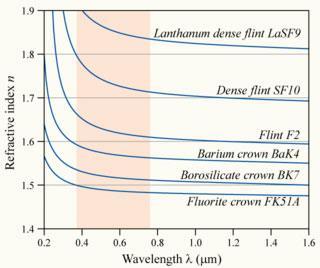
9 LENS MAKER FORMULA curvature r 2 1 f = n 1 n m 1 1 r 1 1 r 2 focal point curvature r1 focal length Factors that determine the focal length of a lens index of refraction index of refraction of the medium radius of the front surface radius of the back surface Material Index Vacuum Air at STP Water at 20 C 1.33 Fluorite Fused quartz 1.46 Glycerine Typical crown glass 1.52 Crown glasses Material Index Flint glasses Heavy flint glass 1.65 Sapphire 1.77 Rare earth flint Lanthanum flint Arsenic trisulfide glass 2.04 Diamond hbase/tables/indrf.html#c1 Spectacle crown, C


10 SIMPLE LENS TYPES
11 GEOMETRICAL OPTICS THIN LENS- IMAGE FORMATION Principal plane -f f 1 f = 1 s s 1 s 0 object optical axis s 1 image s 0 = 5.35 cm s 1 = 14.1 cm f = 3.8 cm 1 s0 = 0.19 cm 1 1 s1 = 0.07 cm 1 1 f = 0.26 cm 1 1 cm
12 GEOMETRICAL OPTICS THIN LENS- VIRTUAL IMAGE FORMATION Principal plane -f f optical axis object image
13 MAGNIFYING GLASS a 2 a 1 virtual image object 250 mm f Magnifier increases the angular size of the object M=a 2 /a 1 Magnification is defined by focal distance of lens M=250/f Maximum magnification of magnifying glass is 10x-20x
14 HOW DOES IT WORK? Practical realisation - 14-

15 COMPOUND MICROSCOPE CONVERGENT BEAM PATH Sample is placed in front of objective focal plane. Intermediate image is formed by objective and is observed through eyepiece
16 DISADVANTAGE OF A CONVERGENT BEAM PATH Convergent beam Beam is focused differently More aberrations Parallel beam Beam is only shifted Less aberration Presence of parallel light beam is microscope light path is important for modern light microscope (for filters, and other optical elements)

17 COMPOUND MICROSCOPE INFINITY-CORRECTED BEAM PATH The sample is placed in the focal plane of the objective. Parallel light beams are focused by the tube lens. The intermediate image is observed through the eyepiece

18 OBJECTIVE Objective are constructed of several high quality lenses. For infinity corrected objective the specimen is in the focal plane For not infinity corrected objectives the specimen is in front of the focal plane

19 EYEPIECE The eyepiece acts as a magnifier of the intermediate image
.")
20 CAMERA AS IMAGE DETECTOR When the camera is used, the intermediate image is directly projected on the camera chip (additionally an intermediate magnifier might be used)

21 ANATOMY OF MICROSCOPE Two independent illumination paths: Transmission Fluorescence Components for contrasting methods: DIC Dark field Phase contrast
22 HOW MICROSCOPE WORKS SUMMARY Magnifying glass has a limited magnification of 10x-20x Compound microscope makes two stage magnification initial magnification with objective further magnification with eyepiece Compound microscope beam path designs finite old microscopes infinity corrected modern microscopes There are several microscope types inverted upright
23 WHAT ARE THE LIMITATIONS OF LIGHT MICROSCOPY? Physical Principles - 23-

24 RAYLEIGH-SOMMERFIELD DIFFRACTION Analytical solutions: Fraunhofer: small aperture, far-field Kirchhoff-Fresnel: small angle, paraxial


25 LIGHT-WAVE THEORY YOUNG: DOUBLE SLIT EXPERIMENT Huygens-Fresnel Principle Each point of a wavefront can be seen as seed point for a new (circular) wave. Richard Feynman: [N]o-one has ever been able to define the difference between interference and diffraction satisfactorily. It is just a question of usage, and there is no specific, important physical difference between them
26 INTERFERENCE OF TWO POINT SOURCES 2 f 2 x 1 2 v 2 f 2 t x f ( x, t) a exp 2 i t k 2 2 wavenumber angular frequency phase velocity v / k f ( x, t) a exp[ i( kx t)] f ( x) a exp[ ikx)] waves in phase f ( x) cos( kx) i sin( k x) f ( y) coskrs i sin( k rs ) coskrs i sin( k rs ) coskr i sin kr S n S n 2 2 r S y d r S ( a y) d

 k =")


27 INTERFERENCE CIRCULAR WAVE Wavelength: 500 nm y r = A 0 cos k r r = ( x 2 + y 2 ) k = 2π λ d / mm Superposition of circular waves k:=wavenumber 20 mm

28 INTERFERENCE OF TWO POINT SOURCES 200 mm 4 I x / mm I = I kdsinθ
29 DIIFRACTION SINGLE SLIT d / mm Intensity 0 I = I 0 sin( Φ 2 ) Φ
 sin 2 ( φ 2 ) φ = k d sinθ -")
30 INTERFERENCE MULTIPLE POINT SOURCES /d /d /d /d x / mm I = I 0 sin 2 N( φ 2 ) sin 2 ( φ 2 ) φ = k d sinθ


31 DIFFRACTION SINGLE SLIT 400 nm d / mm 500 nm 600 nm Intensity Intensity d / mm d / mm 200 mm Intensity


32 DIFFRACTION SINGLE SLIT slit: 20 µm slit: 10 µm slit: 5 µm slit: 0.1 µm 500 nm Intensity Intensity Intensity Intensity d / mm d / mm d / mm d / mm
33 LIGHT-WAVE THEORY FAR FIELD DIFFRACTION Parallel light Observation plane distance R R>1.3 m Slit aperture 100 µm d / mm Circular aperture J. Fraunhofer ( ) J 1 ( Φ I = I 2 ) 0 Φ 4 2 I = I 0 Intensity 0 sin( Φ 2 ) Φ 2 2 Airy disk Φ = k a sinθ sinθ min = 1.22 λ a
34 WHAT ARE THE LIMITATIONS OF LIGHT MICROSCOPY? Practical considerations
35 PRACTICAL CONSIDERATIONS Illumination
36 REQUIREMENTS FOR ILLUMINATION Uniform over whole field of view Has all angles accepted by objective Allows optimize image brightness/contrast Allows continuous change of intensity Allows continuous change of field of view Change in illumination and imaging parts do not effect each other Realized in Kohler illumination
37 ROLE OF CONDENSER IN IMAGE FORMATION NA tot =NA obj +NA cond


38 COLLECTOR AND CONDENSER Collector gathers light from light source Condenser directs light onto the specimen
 Illumination light path (Observed with Bertrand lens) 1. Lamp (filament, arc) 2. Condenser aperture diaphragm 3. Objective rear (back) focal plane 4.")
39 CONJUGATED PLANES IN OPTICAL MICROSCOPY Image forming light path (Observed with eyepiece) 1. Variable field diaphragm 2. Specimen plane 3. Intermediate image plane 4. Image plane (camera, retina) Illumination light path (Observed with Bertrand lens) 1. Lamp (filament, arc) 2. Condenser aperture diaphragm 3. Objective rear (back) focal plane 4. Eyepoint (exit pupil of microscope) Conjugated = imaged onto each other Has one diaphragm in every path If light at given plane is focused in one path, it is parallel in other path
40 PRACTICAL CONSIDERATIONS Numerical Aperture
41 DIFFRACTION ORDERS d = 2 1 st order (d = 5 ) for small enough structures a first diffraction maxima is perpendicular to the direct light d = 1 1 st order (d = 1.5 ) 0 +1 d sina m Direction of diffraction maxima depends on wavelength and period Bigger period results in smaller diffraction angle Bigger wavelength results in bigger diffraction angle

")
42 NUMERICAL APERTURE OF OBJECTIVE NA nsina 0 a 0 n 1!! n The NA defines how much light (brightness) and how many diffraction orders (resolution) are captured by the objective

43 ROLE OF IMMERSION NA=nsina Refractive indices: Air Water Glycerol Oil Immersion media increase the NA of an objective or a condenser by bringing the beams with higher incidence angle into the light path
44 PRACTICAL CONSIDERATIONS Resolution/Contrast - 44-
 of the objective lens is large enough to capture the first-order diffraction")

45 DIFFRACTION LIMITED RESOLUTION d = λ 2 (n sin θ) NA = (n sin θ) Ernst Abbe According to Abbe, a detail with a particular spacing in the specimen is resolved when the numerical aperture (NA) of the objective lens is large enough to capture the first-order diffraction pattern produced by the detail at the wavelength employed. In order to fulfill Abbe's requirements, the angular aperture of the objective must be large enough to admit both the zeroth and first order light waves

46 DEPTH OF FIELD Magnification Numerical Aperture Depth of Field (mm) Image Depth (mm) 4x x x x x x d tot = λ n NA 2 + n M NA e Diffraction limited depth of field Detection system
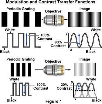
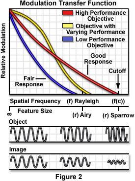
47 MODULATION/CONTRAST
48 EXCURSION Fourier Transformation - 48-
49 SPECTRAL TECHNIQUES Fourier transform Jean Baptiste Fourier ( ): (Almost) every periodic function g(x) can be described as a sum of harmonic sinusoids. Non periodic functions can also be decribed as sums of sine and cosine functions (Fourier integral; infinitely many densley spaced frequencies) Signal Processing Discrete Fourier Transform (DFT); fast algorithm Fast Fourier Transform (FFT) Discrete Cosine Transformation (DCT) - 49-
50 FOURIER ANALYSIS/SYNTHESIS A 1.0 A A A f x = a 0 2 k=1 (a k cos kπt + b k sin(k π t) - 50-
51 FOURIER ANALYSIS/SYNTHESIS f x = a 0 2 k=1 (a k cos kπt + b k sin(k π t) - 51-
52 FREQUENCY SPECTRUM Amplitude f x = a 0 2 k=1 (a k cos kπt + b k sin(k π t) - 52-

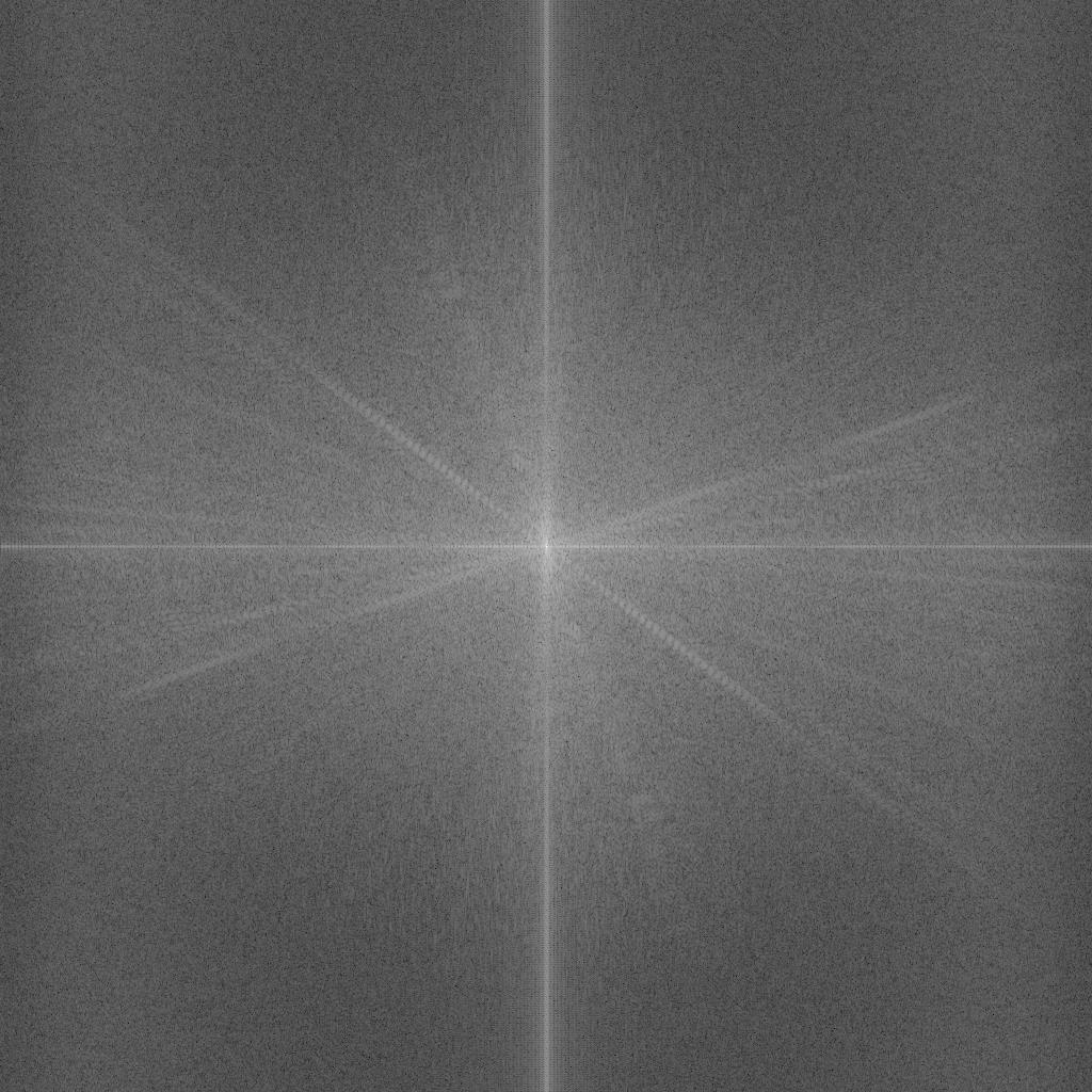
53 FAST FOURIER TRANSFORMATION (FFT) - 53-

54 INVERSE FFT HIGH FREQUENCIES

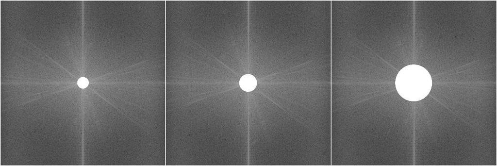
55 INVERSE FFT LOW FREQUENCIES
56 PRACTICAL CONSIDERATIONS Aberrations - 56-
57 MICROSCOPE OPTICS Aberrations in optics Objective engravings Choice of magnification - 57-
58 OPTICAL ABERRATIONS Astigmatism (tangential and meridianal focus are different) Coma (image of dot is not symmetric) Distortion (parallel lines are not parallel in image) Curvature of the field (image of plane is not flat) Chromatic (different focus for different wavelength) Spherical (different focus for on and off axis beams) It is desired to minimize aberrations by proper use of objectives with good aberration correction - 58-

59 SPHERICAL ABERRATION Use cover slip 0.17 mm thick or Use objective with correction ring Avoid refraction index mismatch of immersion and mounting media - 59-

60 CHROMATIC ABERRATION

61 OBJECTIVE TYPES Objective Type Spherical Aberration Chromatic Aberration Field Curvature Achromat 1 Color 2 Colors No Plan Achromat 1 Color 2 Colors Yes Fluorite 2-3 Colors 2-3 Colors No Plan Fluorite 3-4 Colors 2-4 Colors Yes Plan Apochromat 3-4 Colors 4-5 Colors Yes - 61-

62 WORKING DISTANCE AND PARFOCAL LENGTH Parfocal distance Distance from objective shoulder till specimen plane 45 mm for most manufactures, 60 mm for Nikon CFI 60 Working distance Distance from front edge of objective till cover slip Varies from several mm till several hundreds micrometers. Special long working distance objective are available
 Different immersion media under various cover glass conditions -")
63 OBJECTIVES WITH CORRECTION COLLARS NEOFLUAR optics is less color corrected than APOCHROMAT Range of cover glass thickness W W Glyc Oil Ph = phase contrast (3 specifies matching condenser) Different immersion media under various cover glass conditions
64 TOTAL MICROSCOPE MAGNIFICATION Defined by magnification of objective, eyepiece and intermediate magnification M tot =M obj x M int x M eyepiece Objective magnification defined by focal lengths of tube lens and objectives M obj =f tl /f obj Tube lens has a standardized value for specific manufacture Zeiss, Leica, Olympus 165 mm, Nikon 200 mm Typical magnification rangies: M obj : 2x 100x M int : 1.5x 2.5x M obj : 10x 25x
65 USEFUL MAGNIFICATION RANGE Microscope resolution is limited by NA and wavelength. Enlargement of image does not necessarily resolve new features. Excessively large magnification is called empty magnification. (The Airy disk on retina/camera should not exceed two cell/pixel sizes). Useful magnification = x NA of objective M obj M eyepiece NA obj M tot M useful Magnification 10x 10x low 40x 10x ok 100x 10x ok 100x 15x empty
66 MICROSCOPE OPTICS SUMMARY Correct choice of microscope optics is the key to successful imaging Pay attention to the engravings on objective and eyepiece Optical aberrations can be minimized use well corrected optics or use green filter use cover slip 0.17 mm thick match refractive index of immersion media and specimen Choose magnification carefully excessive magnification does not reveal new details moreover it deceases the brightness of the image
67 CONTRASTING METHODS Dark field Phase contrast DIC PlasDIC - 67-

68 AMPLITUDE AND PHASE SPECIMENS Amplitude specimen changes the intensity of incident light Phase specimen changes the phase of incident light Most unstained biological specimens are phase ones


69 EXAMPLES OF CONTRASTING METHODS Dark field Bone thin section Phase contrast HEK cells DIC Neurons PlasDIC HEK cells

70 DARKFIELD CONTRAST 5 iris diaphragm 4 - objective 3 - sample 2 - condenser 1 - phase stop A - low NA objective B - high NA objective with iris Required: special condenser, sometimes immersion oil Principle: direct light is rejected or blocked, only scattered light is observed Disadvantage: low resolution
71 INTERFERENCE Addition of waves Amplitude of the resulting wave depends on the pahse relation of two waves Extreme cases: destructive interference (res. amplitude =0) positive interference With interference a phase difference can be turned into an amplitude difference Interference is the basic principle of Phase contrast and DIC

72 PHASE CONTRAST MICROSCOPY

73 PHASE CONTRAST MICROSCOPY 9 - intermediate image 8 - tube lense 7 - indirect light 6 - direct light 5 - phase ring 4 - objective 3 - sample 2 - condenser 1 - phase stop Required: special objectives and special condensers. Principle: direct light is attenuated and its phase is shifted 90. Contrast formed due to interference between direct and scattered light. Disadvantages: relatively low resolution, halos
. Principle: specimen is sensed with two linear polarized slightly shifted (< ) light beams.")
74 DIFFERENTIAL INTERFERENCE CONTRAST 9 - intermediate image 8 - tube lens 7 analyzer 7a - λ-plate 6 - Wollaston prism 5 objective 4 sample 3 condenser 2 Wollaston prism 1 - polariser Required: special accessories in light path (prisms, polarizers). Principle: specimen is sensed with two linear polarized slightly shifted (< ) light beams. Difference in optical path of the beams gives a contrast in image. Disadvantages: accessories are relatively expensive


75 DIC IN DETAILS DIC prism split beam into two perpendicularly polarized. Shift between beams less that resolution of microscope. Beams measure difference in optical path in specimen. If retardation is not zero, they are interfere after being recombined on the second DIC prism

76 PLASDIC Required: slit diaphragm, prism with polarizer, analyzer. Principle: A slit diaphragm creates a pair of non-polarized light beams that are /4 out-of-phase. The beams get polarized just before being recombined into a single beam in the DIC-prism. The analyzer (linear) sets a single polarization plane where the components of the beam can interfere
77 CONTRASTING TECHNIQUES SUMMARY Dark field Fine structural features at, and even below, the resolution limit of a light microscope. Highly suitable for metallographic and crystallographic examinations with reflected light. Phase contrast Used for visualizing very fine structural features in tissues and single cells contained in very thin (< 5 µm), non-stained specimens. DIC Method shows optical path differences in the specimen in a relieflike fashion. The method is excellently suited for thick, non-stained specimens (> 5 µm). Can be used for optical sectioning. PlasDIC The same specimen as conventional DIC but in plastic dishes
 imaged")

78 IMAGES ARE ARTEFACTS Two images of same object (sample) imaged with the same microscope/objective! Object Image of Object
79 MORE ABOUT LIGHT MICROSCOPY 1. Lecture Biomicroscopy I + II, Prof. Theo Lasser, EPFL 2. Books a) Digital microscopy, Sluder, G; Wolf, D.E., eds, Elsevier, 2003 b) Optics, 4th ed., Eugene Hecht, Addison-Wesley, Internet a) b) b) Web sites of microscope manufactures Leica Nikon Olympus Zeiss 4. BIOp EPFL, SV-AI 0241, Sv-AI
80 Acknowledgments These slides are based on a lecture given by Yuri Belyaev (Advanced Light Microscopy Facility, EMBL Heidelberg) during a practical course concerning basics of light microscopy. Thus a big thank to him for providing them and making them available also here at EPFL
BIOIMAGING AND OPTICS PLATFORM EPFL SV PTBIOP BASICS IN LIGHT MICROSCOPY
 BASICS IN LIGHT MICROSCOPY INTERNAL COURSE 2014 13 TH JANUARY OVERVIEW 1. Motivation 2. Basic in optics 3. How microscope works 4. Illumination and resolution 5. Microscope optics 6. Contrasting methods
BASICS IN BIOIMAGING AND OPTICS PLATFORM EPFL SV PTBIOP LIGHT MICROSCOPY
 BASICS IN LIGHT MICROSCOPY OVERVIEW 1. Motivation 2. Basic in optics 3. How microscope works 4. Illumination and resolution 5. Microscope optics 6. Contrasting methods -2- MOTIVATION Why do we need microscopy?
Microscope anatomy, image formation and resolution
 Microscope anatomy, image formation and resolution Ian Dobbie Buy this book for your lab: D.B. Murphy, "Fundamentals of light microscopy and electronic imaging", ISBN 0-471-25391-X Visit these websites:
Introduction to Light Microscopy. (Image: T. Wittman, Scripps)
") Introduction to Light Microscopy (Image: T. Wittman, Scripps) The Light Microscope Four centuries of history Vibrant current development One of the most widely used research tools A. Khodjakov et al. Major
Introduction to Light Microscopy (Image: T. Wittman, Scripps) The Light Microscope Four centuries of history Vibrant current development One of the most widely used research tools A. Khodjakov et al. Major
Microscopy: Fundamental Principles and Practical Approaches
 Microscopy: Fundamental Principles and Practical Approaches Simon Atkinson Online Resource: http://micro.magnet.fsu.edu/primer/index.html Book: Murphy, D.B. Fundamentals of Light Microscopy and Electronic
microscopy A great online resource Molecular Expressions, a Microscope Primer Partha Roy
 Fundamentals of optical microscopy A great online resource Molecular Expressions, a Microscope Primer http://micro.magnet.fsu.edu/primer/index.html Partha Roy 1 Why microscopy Topics Functions of a microscope
Imaging Introduction. September 24, 2010
 Imaging Introduction September 24, 2010 What is a microscope? Merriam-Webster: an optical instrument consisting of a lens or combination of lenses for making enlarged images of minute objects; especially:
INTRODUCTION THIN LENSES. Introduction. given by the paraxial refraction equation derived last lecture: Thin lenses (19.1) = 1. Double-lens systems
 = 1. Double-lens systems") Chapter 9 OPTICAL INSTRUMENTS Introduction Thin lenses Double-lens systems Aberrations Camera Human eye Compound microscope Summary INTRODUCTION Knowledge of geometrical optics, diffraction and interference,
Chapter 9 OPTICAL INSTRUMENTS Introduction Thin lenses Double-lens systems Aberrations Camera Human eye Compound microscope Summary INTRODUCTION Knowledge of geometrical optics, diffraction and interference,
Very short introduction to light microscopy and digital imaging
 Very short introduction to light microscopy and digital imaging Hernan G. Garcia August 1, 2005 1 Light Microscopy Basics In this section we will briefly describe the basic principles of operation and
Education in Microscopy and Digital Imaging
 Contact Us Carl Zeiss Education in Microscopy and Digital Imaging ZEISS Home Products Solutions Support Online Shop ZEISS International ZEISS Campus Home Interactive Tutorials Basic Microscopy Spectral
OPTICAL SYSTEMS OBJECTIVES
 101 L7 OPTICAL SYSTEMS OBJECTIVES Aims Your aim here should be to acquire a working knowledge of the basic components of optical systems and understand their purpose, function and limitations in terms
Chapter 25. Optical Instruments
 Chapter 25 Optical Instruments Optical Instruments Analysis generally involves the laws of reflection and refraction Analysis uses the procedures of geometric optics To explain certain phenomena, the wave
VISUAL PHYSICS ONLINE DEPTH STUDY: ELECTRON MICROSCOPES
 VISUAL PHYSICS ONLINE DEPTH STUDY: ELECTRON MICROSCOPES Shortly after the experimental confirmation of the wave properties of the electron, it was suggested that the electron could be used to examine objects
Systems Biology. Optical Train, Köhler Illumination
 McGill University Life Sciences Complex Imaging Facility Systems Biology Microscopy Workshop Tuesday December 7 th, 2010 Simple Lenses, Transmitted Light Optical Train, Köhler Illumination What Does a
Reflection! Reflection and Virtual Image!
 1/30/14 Reflection - wave hits non-absorptive surface surface of a smooth water pool - incident vs. reflected wave law of reflection - concept for all electromagnetic waves - wave theory: reflected back
OPTICAL PRINCIPLES OF MICROSCOPY. Interuniversity Course 28 December 2003 Aryeh M. Weiss Bar Ilan University
 OPTICAL PRINCIPLES OF MICROSCOPY Interuniversity Course 28 December 2003 Aryeh M. Weiss Bar Ilan University FOREWORD This slide set was originally presented at the ISM Workshop on Theoretical and Experimental
PHY 431 Homework Set #5 Due Nov. 20 at the start of class
 PHY 431 Homework Set #5 Due Nov. 0 at the start of class 1) Newton s rings (10%) The radius of curvature of the convex surface of a plano-convex lens is 30 cm. The lens is placed with its convex side down
Applied Optics. , Physics Department (Room #36-401) , ,
 , ,") Applied Optics Professor, Physics Department (Room #36-401) 2290-0923, 019-539-0923, shsong@hanyang.ac.kr Office Hours Mondays 15:00-16:30, Wednesdays 15:00-16:30 TA (Ph.D. student, Room #36-415) 2290-0921,
Applied Optics Professor, Physics Department (Room #36-401) 2290-0923, 019-539-0923, shsong@hanyang.ac.kr Office Hours Mondays 15:00-16:30, Wednesdays 15:00-16:30 TA (Ph.D. student, Room #36-415) 2290-0921,
Chapter 3 Op,cal Instrumenta,on
 Imaging by an Op,cal System Change in curvature of wavefronts by a thin lens Chapter 3 Op,cal Instrumenta,on 3-1 Stops, Pupils, and Windows 3-4 The Camera 3-5 Simple Magnifiers and Eyepieces 1. Magnifiers
2/4/15. Brightfield Microscopy! It s all about Magnification..! or is it?!
 Brightfield Microscopy It s all about Magnification.. or is it? 1 What actually does go into chosing a microscope Choice depends on what you need the microscope to do. Do you want to magnify stained specimens?
Katarina Logg, Kristofer Bodvard, Mikael Käll. Dept. of Applied Physics. 12 September Optical Microscopy. Supervisor s signature:...
 Katarina Logg, Kristofer Bodvard, Mikael Käll Dept. of Applied Physics 12 September 2007 O1 Optical Microscopy Name:.. Date:... Supervisor s signature:... Introduction Over the past decades, the number
R.B.V.R.R. WOMEN S COLLEGE (AUTONOMOUS) Narayanaguda, Hyderabad.
 Narayanaguda, Hyderabad.") R.B.V.R.R. WOMEN S COLLEGE (AUTONOMOUS) Narayanaguda, Hyderabad. DEPARTMENT OF PHYSICS QUESTION BANK FOR SEMESTER III PAPER III OPTICS UNIT I: 1. MATRIX METHODS IN PARAXIAL OPTICS 2. ABERATIONS UNIT II
R.B.V.R.R. WOMEN S COLLEGE (AUTONOMOUS) Narayanaguda, Hyderabad. DEPARTMENT OF PHYSICS QUESTION BANK FOR SEMESTER III PAPER III OPTICS UNIT I: 1. MATRIX METHODS IN PARAXIAL OPTICS 2. ABERATIONS UNIT II
CCAM s Selection of. Zeiss Microscope Objectives
 CCAM s Selection of Zeiss Microscope Objectives 1. Magnification Image scale 2. Resolution The minimum separation distance between two points that are clearly resolved. The resolution of an objective is
CCAM Microscope Objectives
 CCAM Microscope Objectives Things to consider when selecting an objective Magnification Numerical Aperture (NA) resolving power and light intensity of the objective Working Distance distance between the
Lecture 2: Geometrical Optics. Geometrical Approximation. Lenses. Mirrors. Optical Systems. Images and Pupils. Aberrations.
 Lecture 2: Geometrical Optics Outline 1 Geometrical Approximation 2 Lenses 3 Mirrors 4 Optical Systems 5 Images and Pupils 6 Aberrations Christoph U. Keller, Leiden Observatory, keller@strw.leidenuniv.nl
GIST OF THE UNIT BASED ON DIFFERENT CONCEPTS IN THE UNIT (BRIEFLY AS POINT WISE). RAY OPTICS
. RAY OPTICS") 209 GIST OF THE UNIT BASED ON DIFFERENT CONCEPTS IN THE UNIT (BRIEFLY AS POINT WISE). RAY OPTICS Reflection of light: - The bouncing of light back into the same medium from a surface is called reflection
209 GIST OF THE UNIT BASED ON DIFFERENT CONCEPTS IN THE UNIT (BRIEFLY AS POINT WISE). RAY OPTICS Reflection of light: - The bouncing of light back into the same medium from a surface is called reflection
Opti 415/515. Introduction to Optical Systems. Copyright 2009, William P. Kuhn
 Opti 415/515 Introduction to Optical Systems 1 Optical Systems Manipulate light to form an image on a detector. Point source microscope Hubble telescope (NASA) 2 Fundamental System Requirements Application
PHYSICS. Chapter 35 Lecture FOR SCIENTISTS AND ENGINEERS A STRATEGIC APPROACH 4/E RANDALL D. KNIGHT
 PHYSICS FOR SCIENTISTS AND ENGINEERS A STRATEGIC APPROACH 4/E Chapter 35 Lecture RANDALL D. KNIGHT Chapter 35 Optical Instruments IN THIS CHAPTER, you will learn about some common optical instruments and
SUBJECT: PHYSICS. Use and Succeed.
 SUBJECT: PHYSICS I hope this collection of questions will help to test your preparation level and useful to recall the concepts in different areas of all the chapters. Use and Succeed. Navaneethakrishnan.V
Lecture 2: Geometrical Optics. Geometrical Approximation. Lenses. Mirrors. Optical Systems. Images and Pupils. Aberrations.
 Lecture 2: Geometrical Optics Outline 1 Geometrical Approximation 2 Lenses 3 Mirrors 4 Optical Systems 5 Images and Pupils 6 Aberrations Christoph U. Keller, Leiden Observatory, keller@strw.leidenuniv.nl
Chapter 3 Op+cal Instrumenta+on
 Chapter 3 Op+cal Instrumenta+on 3-1 Stops, Pupils, and Windows 3-4 The Camera 3-5 Simple Magnifiers and Eyepieces 3-6 Microscopes 3-7 Telescopes Today (2011-09-22) 1. Magnifiers 2. Camera 3. Resolution
Lecture 8. Lecture 8. r 1
 Lecture 8 Achromat Design Design starts with desired Next choose your glass materials, i.e. Find P D P D, then get f D P D K K Choose radii (still some freedom left in choice of radii for minimization
FLUORESCENCE MICROSCOPY. Matyas Molnar and Dirk Pacholsky
 FLUORESCENCE MICROSCOPY Matyas Molnar and Dirk Pacholsky 1 The human eye perceives app. 400-700 nm; best at around 500 nm (green) Has a general resolution down to150-300 μm (human hair: 40-250 μm) We need
Basics of Light Microscopy and Metallography
 ENGR45: Introduction to Materials Spring 2012 Laboratory 8 Basics of Light Microscopy and Metallography In this exercise you will: gain familiarity with the proper use of a research-grade light microscope
Lecture 23 MNS 102: Techniques for Materials and Nano Sciences
 Lecture 23 MNS 102: Techniques for Materials and Nano Sciences Reference: #1 C. R. Brundle, C. A. Evans, S. Wilson, "Encyclopedia of Materials Characterization", Butterworth-Heinemann, Toronto (1992),
Phys 102 Lecture 21 Optical instruments
 Phys 102 Lecture 21 Optical instruments 1 Today we will... Learn how combinations of lenses form images Thin lens equation & magnification Learn about the compound microscope Eyepiece & objective Total
Properties of optical instruments. Visual optical systems part 2: focal visual instruments (microscope type)
") Properties of optical instruments Visual optical systems part 2: focal visual instruments (microscope type) Examples of focal visual instruments magnifying glass Eyepieces Measuring microscopes from the
Properties of optical instruments Visual optical systems part 2: focal visual instruments (microscope type) Examples of focal visual instruments magnifying glass Eyepieces Measuring microscopes from the
Microscopy Training & Overview
 Microscopy Training & Overview Product Marketing October 2011 Stephan Briggs - PLE OVERVIEW AND PRESENTATION FLOW Glossary and Important Terms Introduction Timeline Innovation and Advancement Primary Components
Phy Ph s y 102 Lecture Lectur 21 Optical instruments 1
 Phys 102 Lecture 21 Optical instruments 1 Today we will... Learn how combinations of lenses form images Thin lens equation & magnification Learn about the compound microscope Eyepiece & objective Total
 Microscopy http://www.microscopyu.com/articles/phasecontrast/phasemicroscopy.html http://micro.magnet.fsu.edu/primer/anatomy/anatomy.html 2005, Dr. Jack Ikeda & Dr. Gail Grabner 9 Nikon Labophot (Question
Overview of the Microscope Objective
 Overview of the Microscope Objective Item Type text; Electronic Thesis Authors Niu, Ruijuan Publisher The University of Arizona. Rights Copyright is held by the author. Digital access to this material
ECEN 4606, UNDERGRADUATE OPTICS LAB
 ECEN 4606, UNDERGRADUATE OPTICS LAB Lab 2: Imaging 1 the Telescope Original Version: Prof. McLeod SUMMARY: In this lab you will become familiar with the use of one or more lenses to create images of distant
Physics 3340 Spring Fourier Optics
 Physics 3340 Spring 011 Purpose Fourier Optics In this experiment we will show how the Fraunhofer diffraction pattern or spatial Fourier transform of an object can be observed within an optical system.
Physics 1C. Lecture 25B
 Physics 1C Lecture 25B "More than 50 years ago, Austrian researcher Ivo Kohler gave people goggles thats severely distorted their vision: The lenses turned the world upside down. After several weeks, subjects
The Compound Microscope. Brightfield: Köhler Illumination
 Outline History of Microscopy The Magnifying Glass The Compound Microscope Brightfield: Köhler Illumination Microscopy µικροσ (mikros): small σκοπειν (skopein): to observe History of Microscopy Well :
Chapter 36. Image Formation
 Chapter 36 Image Formation Image of Formation Images can result when light rays encounter flat or curved surfaces between two media. Images can be formed either by reflection or refraction due to these
Physics 431 Final Exam Examples (3:00-5:00 pm 12/16/2009) TIME ALLOTTED: 120 MINUTES Name: Signature:
 TIME ALLOTTED: 120 MINUTES Name: Signature:") Physics 431 Final Exam Examples (3:00-5:00 pm 12/16/2009) TIME ALLOTTED: 120 MINUTES Name: PID: Signature: CLOSED BOOK. TWO 8 1/2 X 11 SHEET OF NOTES (double sided is allowed), AND SCIENTIFIC POCKET CALCULATOR
Physics 431 Final Exam Examples (3:00-5:00 pm 12/16/2009) TIME ALLOTTED: 120 MINUTES Name: PID: Signature: CLOSED BOOK. TWO 8 1/2 X 11 SHEET OF NOTES (double sided is allowed), AND SCIENTIFIC POCKET CALCULATOR
Microscopy. Matti Hotokka Department of Physical Chemistry Åbo Akademi University
 Microscopy Matti Hotokka Department of Physical Chemistry Åbo Akademi University What s coming Anatomy of a microscope Modes of illumination Practicalities Special applications Basic microscope Ocular
MICROSCOPE LAB. Resolving Power How well specimen detail is preserved during the magnifying process.
 AP BIOLOGY Cells ACTIVITY #2 MICROSCOPE LAB OBJECTIVES 1. Demonstrate proper care and use of a compound microscope. 2. Identify the parts of the microscope and describe the function of each part. 3. Compare
Biology 29 Cell Structure and Function Spring, 2009 Springer LABORATORY 1: THE LIGHT MICROSCOPE
 Biology 29 Cell Structure and Function Spring, 2009 Springer LABORATORY 1: THE LIGHT MICROSCOPE Prior to lab: 1) Read these instructions (p 1-6) 2) Go through the online tutorial, the microscopy pre-lab
PHYS 202 OUTLINE FOR PART III LIGHT & OPTICS
 PHYS 202 OUTLINE FOR PART III LIGHT & OPTICS Electromagnetic Waves A. Electromagnetic waves S-23,24 1. speed of waves = 1/( o o ) ½ = 3 x 10 8 m/s = c 2. waves and frequency: the spectrum (a) radio red
Microscopy Techniques that make it easy to see things this small.
 Microscopy Techniques that make it easy to see things this small. What is a Microscope? An instrument for viewing objects that are too small to be seen easily by the naked eye. Dutch spectacle-makers Hans
Chapter 36. Image Formation
 Chapter 36 Image Formation Notation for Mirrors and Lenses The object distance is the distance from the object to the mirror or lens Denoted by p The image distance is the distance from the image to the
There is a range of distances over which objects will be in focus; this is called the depth of field of the lens. Objects closer or farther are
 Chapter 25 Optical Instruments Some Topics in Chapter 25 Cameras The Human Eye; Corrective Lenses Magnifying Glass Telescopes Compound Microscope Aberrations of Lenses and Mirrors Limits of Resolution
TOPICS Recap of PHYS110-1 lecture Physical Optics - 4 lectures EM spectrum and colour Light sources Interference and diffraction Polarization
 TOPICS Recap of PHYS110-1 lecture Physical Optics - 4 lectures EM spectrum and colour Light sources Interference and diffraction Polarization Lens Aberrations - 3 lectures Spherical aberrations Coma, astigmatism,
Optical System Design
 Phys 531 Lecture 12 14 October 2004 Optical System Design Last time: Surveyed examples of optical systems Today, discuss system design Lens design = course of its own (not taught by me!) Try to give some
Optical Design of. Microscopes. George H. Seward. Tutorial Texts in Optical Engineering Volume TT88. SPIE PRESS Bellingham, Washington USA
 Optical Design of Microscopes George H. Seward Tutorial Texts in Optical Engineering Volume TT88 SPIE PRESS Bellingham, Washington USA Preface xiii Chapter 1 Optical Design Concepts /1 1.1 A Value Proposition
Resolution. Diffraction from apertures limits resolution. Rayleigh criterion θ Rayleigh = 1.22 λ/d 1 peak at 2 nd minimum. θ f D
 Microscopy Outline 1. Resolution and Simple Optical Microscope 2. Contrast enhancement: Dark field, Fluorescence (Chelsea & Peter), Phase Contrast, DIC 3. Newer Methods: Scanning Tunneling microscopy (STM),
Basics of confocal imaging (part I)
") Basics of confocal imaging (part I) Swiss Institute of Technology (EPFL) Faculty of Life Sciences Head of BIOIMAGING AND OPTICS BIOP arne.seitz@epfl.ch Lateral resolution BioImaging &Optics Platform Light
Basics of confocal imaging (part I) Swiss Institute of Technology (EPFL) Faculty of Life Sciences Head of BIOIMAGING AND OPTICS BIOP arne.seitz@epfl.ch Lateral resolution BioImaging &Optics Platform Light
EE119 Introduction to Optical Engineering Spring 2002 Final Exam. Name:
 EE119 Introduction to Optical Engineering Spring 2002 Final Exam Name: SID: CLOSED BOOK. FOUR 8 1/2 X 11 SHEETS OF NOTES, AND SCIENTIFIC POCKET CALCULATOR PERMITTED. TIME ALLOTTED: 180 MINUTES Fundamental
Average: Standard Deviation: Max: 99 Min: 40
 1 st Midterm Exam Average: 83.1 Standard Deviation: 12.0 Max: 99 Min: 40 Please contact me to fix an appointment, if you took less than 65. Chapter 33 Lenses and Op/cal Instruments Units of Chapter 33
Chapter Ray and Wave Optics
 109 Chapter Ray and Wave Optics 1. An astronomical telescope has a large aperture to [2002] reduce spherical aberration have high resolution increase span of observation have low dispersion. 2. If two
Biomedical Imaging 生物醫學影像學
 Biomedical Imaging 生物醫學影像學 楊自森助理教授 牙體技術學系 2013/02/24 tsyang@tmu.edu.tw 1 Course Outline 1. Course Introduction 2. Basic Optics and Light Microscopes 3. Fluorescence/Confocal/TIRF Microscopes 4. FRET Techniques
Exam 4. Name: Class: Date: Multiple Choice Identify the choice that best completes the statement or answers the question.
 Name: Class: Date: Exam 4 Multiple Choice Identify the choice that best completes the statement or answers the question. 1. Mirages are a result of which physical phenomena a. interference c. reflection
Reading: Lenses and Mirrors; Applications Key concepts: Focal points and lengths; real images; virtual images; magnification; angular magnification.
 Reading: Lenses and Mirrors; Applications Key concepts: Focal points and lengths; real images; virtual images; magnification; angular magnification. 1.! Questions about objects and images. Can a virtual
PHYSICS FOR THE IB DIPLOMA CAMBRIDGE UNIVERSITY PRESS
 Option C Imaging C Introduction to imaging Learning objectives In this section we discuss the formation of images by lenses and mirrors. We will learn how to construct images graphically as well as algebraically.
GEOMETRICAL OPTICS AND OPTICAL DESIGN
 GEOMETRICAL OPTICS AND OPTICAL DESIGN Pantazis Mouroulis Associate Professor Center for Imaging Science Rochester Institute of Technology John Macdonald Senior Lecturer Physics Department University of
Chapter 25 Optical Instruments
 Chapter 25 Optical Instruments Units of Chapter 25 Cameras, Film, and Digital The Human Eye; Corrective Lenses Magnifying Glass Telescopes Compound Microscope Aberrations of Lenses and Mirrors Limits of
Introduction. Geometrical Optics. Milton Katz State University of New York. VfeWorld Scientific New Jersey London Sine Singapore Hong Kong
 Introduction to Geometrical Optics Milton Katz State University of New York VfeWorld Scientific «New Jersey London Sine Singapore Hong Kong TABLE OF CONTENTS PREFACE ACKNOWLEDGMENTS xiii xiv CHAPTER 1:
Lecture 4: Geometrical Optics 2. Optical Systems. Images and Pupils. Rays. Wavefronts. Aberrations. Outline
 Lecture 4: Geometrical Optics 2 Outline 1 Optical Systems 2 Images and Pupils 3 Rays 4 Wavefronts 5 Aberrations Christoph U. Keller, Leiden University, keller@strw.leidenuniv.nl Lecture 4: Geometrical
EE119 Introduction to Optical Engineering Spring 2003 Final Exam. Name:
 EE119 Introduction to Optical Engineering Spring 2003 Final Exam Name: SID: CLOSED BOOK. THREE 8 1/2 X 11 SHEETS OF NOTES, AND SCIENTIFIC POCKET CALCULATOR PERMITTED. TIME ALLOTTED: 180 MINUTES Fundamental
Lecture 21. Physics 1202: Lecture 21 Today s Agenda
 Physics 1202: Lecture 21 Today s Agenda Announcements: Team problems today Team 14: Gregory Desautels, Benjamin Hallisey, Kyle Mcginnis Team 15: Austin Dion, Nicholas Gandza, Paul Macgillis-Falcon Homework
 6. OPTICS RAY OPTICS GIST. Reflection by convex and concave mirrors. a. Mirror formula, where u is the object distance, v is the image distance and f is v u f the focal length. v f v f b. Magnification
Lecture 3: Geometrical Optics 1. Spherical Waves. From Waves to Rays. Lenses. Chromatic Aberrations. Mirrors. Outline
 Lecture 3: Geometrical Optics 1 Outline 1 Spherical Waves 2 From Waves to Rays 3 Lenses 4 Chromatic Aberrations 5 Mirrors Christoph U. Keller, Leiden Observatory, keller@strw.leidenuniv.nl Lecture 3: Geometrical
25 cm. 60 cm. 50 cm. 40 cm.
 Geometrical Optics 7. The image formed by a plane mirror is: (a) Real. (b) Virtual. (c) Erect and of equal size. (d) Laterally inverted. (e) B, c, and d. (f) A, b and c. 8. A real image is that: (a) Which
Tissue Preparation ORGANISM IMAGE TISSUE PREPARATION. 1) Fixation: halts cell metabolism, preserves cell/tissue structure
 Fixation: halts cell metabolism, preserves cell/tissue structure") Lab starts this week! ANNOUNCEMENTS - Tuesday or Wednesday 1:25 ISB 264 - Read Lab 1: Microscopy and Imaging (see Web Page) - Getting started on Lab Group project - Organ for investigation - Lab project
Lab starts this week! ANNOUNCEMENTS - Tuesday or Wednesday 1:25 ISB 264 - Read Lab 1: Microscopy and Imaging (see Web Page) - Getting started on Lab Group project - Organ for investigation - Lab project
Properties of optical instruments. Projection optical systems
 Properties of optical instruments Projection optical systems Instruments : optical systems designed for a specific function Projection systems: : real image (object real or at infinity) Examples: videoprojector,,
Microscopy. Lecture 2: Optical System of the Microscopy II Herbert Gross. Winter term
 Microscopy Lecture 2: Optical System of the Microscopy II 212-1-22 Herbert Gross Winter term 212 www.iap.uni-jena.de Preliminary time schedule 2 No Date Main subject Detailed topics Lecturer 1 15.1. Optical
Lecture Outline Chapter 27. Physics, 4 th Edition James S. Walker. Copyright 2010 Pearson Education, Inc.
 Lecture Outline Chapter 27 Physics, 4 th Edition James S. Walker Chapter 27 Optical Instruments Units of Chapter 27 The Human Eye and the Camera Lenses in Combination and Corrective Optics The Magnifying
Observing Microorganisms through a Microscope LIGHT MICROSCOPY: This type of microscope uses visible light to observe specimens. Compound Light Micros
 PHARMACEUTICAL MICROBIOLOGY JIGAR SHAH INSTITUTE OF PHARMACY NIRMA UNIVERSITY Observing Microorganisms through a Microscope LIGHT MICROSCOPY: This type of microscope uses visible light to observe specimens.
Chapter 29/30. Wave Fronts and Rays. Refraction of Sound. Dispersion in a Prism. Index of Refraction. Refraction and Lenses
 Chapter 29/30 Refraction and Lenses Refraction Refraction the bending of waves as they pass from one medium into another. Caused by a change in the average speed of light. Analogy A car that drives off
Cardinal Points of an Optical System--and Other Basic Facts
 Cardinal Points of an Optical System--and Other Basic Facts The fundamental feature of any optical system is the aperture stop. Thus, the most fundamental optical system is the pinhole camera. The image
Converging and Diverging Surfaces. Lenses. Converging Surface
 Lenses Sandy Skoglund 2 Converging and Diverging s AIR Converging If the surface is convex, it is a converging surface in the sense that the parallel rays bend toward each other after passing through the
Observing Microorganisms through a Microscope
 2016/2/19 PowerPoint Lecture Presentations prepared by Bradley W. Christian, McLennan Community College CHAPTER 3 Observing Microorganisms through a Microscope 1 Figure 3.2 Microscopes and Magnification.
Optical Systems: Pinhole Camera Pinhole camera: simple hole in a box: Called Camera Obscura Aristotle discussed, Al-Hazen analyzed in Book of Optics
 Optical Systems: Pinhole Camera Pinhole camera: simple hole in a box: Called Camera Obscura Aristotle discussed, Al-Hazen analyzed in Book of Optics 1011CE Restricts rays: acts as a single lens: inverts
GEOMETRICAL OPTICS Practical 1. Part I. BASIC ELEMENTS AND METHODS FOR CHARACTERIZATION OF OPTICAL SYSTEMS
 GEOMETRICAL OPTICS Practical 1. Part I. BASIC ELEMENTS AND METHODS FOR CHARACTERIZATION OF OPTICAL SYSTEMS Equipment and accessories: an optical bench with a scale, an incandescent lamp, matte, a set of
The Nature of Light. Light and Energy
 The Nature of Light Light and Energy - dependent on energy from the sun, directly and indirectly - solar energy intimately associated with existence of life -light absorption: dissipate as heat emitted
Bio 407. Applied microscopy. Introduction into light microscopy. José María Mateos. Center for Microscopy and Image Analysis
 Center for Microscopy and Image Analysis Bio 407 Applied Introduction into light José María Mateos Fundamentals of light Compound microscope Microscope composed of an objective and an additional lens (eyepiece,
Name. Light Chapter Summary Cont d. Refraction
 Page 1 of 17 Physics Week 12(Sem. 2) Name Light Chapter Summary Cont d with a smaller index of refraction to a material with a larger index of refraction, the light refracts towards the normal line. Also,
Instruction Manual T Binocular Acromat Research Scope T Trinocular Acromat Research Scope
 Research Scope Instruction Manual T-29031 Binocular Acromat Research Scope T-29041 Trinocular Acromat Research Scope T-29032 Binocular Semi-Plan Research Scope T-29042 Trinocular Semi-Plan Research Scope
Chapter 34 Geometric Optics (also known as Ray Optics) by C.-R. Hu
 by C.-R. Hu") Chapter 34 Geometric Optics (also known as Ray Optics) by C.-R. Hu 1. Principles of image formation by mirrors (1a) When all length scales of objects, gaps, and holes are much larger than the wavelength
Chapter 34 Geometric Optics (also known as Ray Optics) by C.-R. Hu 1. Principles of image formation by mirrors (1a) When all length scales of objects, gaps, and holes are much larger than the wavelength
WHS-CH-23 Light: Geometric Optics Show all your work, equations used, and box in your answers!
 WHS-CH-23 Light: Geometric Optics Show all your work, equations used, and box in your answers! Willebrord Snell (1591-1626) Snell developed methods for measuring the Earth. He proposed the method of triangulation
ECEG105/ECEU646 Optics for Engineers Course Notes Part 4: Apertures, Aberrations Prof. Charles A. DiMarzio Northeastern University Fall 2008
 ECEG105/ECEU646 Optics for Engineers Course Notes Part 4: Apertures, Aberrations Prof. Charles A. DiMarzio Northeastern University Fall 2008 July 2003+ Chuck DiMarzio, Northeastern University 11270-04-1
Light microscopy BMB 173, Lecture 14, Feb. 21, 2018
 Light microscopy The Structural Biology Continuum Next two lectures: Light microscopy Many slides taken from Scott Fraser, Murphy s Fundamentals of light microscopy, Alberts Molecular Biology of the Cell,
Section A Conceptual and application type questions. 1 Which is more observable diffraction of light or sound? Justify. (1)
") INDIAN SCHOOL MUSCAT Department of Physics Class : XII Physics Worksheet - 6 (2017-2018) Chapter 9 and 10 : Ray Optics and wave Optics Section A Conceptual and application type questions 1 Which is more
INDIAN SCHOOL MUSCAT Department of Physics Class : XII Physics Worksheet - 6 (2017-2018) Chapter 9 and 10 : Ray Optics and wave Optics Section A Conceptual and application type questions 1 Which is more
INTRODUCTION TO OPTICAL MICROSCOPY
 Experimental Biophysics TEK265, FYST23, TNF060, FAF010F Lab Exercise Supervisor: Karl Adolfsson Written by Peter Jönsson and Jason Beech Updated by Henrik Persson, Karl Adolfsson and Zhen Li karl.adolfsson@ftf.lth.se
CHAPTER TWO METALLOGRAPHY & MICROSCOPY
 CHAPTER TWO METALLOGRAPHY & MICROSCOPY 1. INTRODUCTION: Materials characterisation has two main aspects: Accurately measuring the physical, mechanical and chemical properties of materials Accurately measuring
Physics 11. Unit 8 Geometric Optics Part 2
 Physics 11 Unit 8 Geometric Optics Part 2 (c) Refraction (i) Introduction: Snell s law Like water waves, when light is traveling from one medium to another, not only does its wavelength, and in turn the
Mirrors and Lenses. Images can be formed by reflection from mirrors. Images can be formed by refraction through lenses.
 Mirrors and Lenses Images can be formed by reflection from mirrors. Images can be formed by refraction through lenses. Notation for Mirrors and Lenses The object distance is the distance from the object
EE-527: MicroFabrication
 EE-57: MicroFabrication Exposure and Imaging Photons white light Hg arc lamp filtered Hg arc lamp excimer laser x-rays from synchrotron Electrons Ions Exposure Sources focused electron beam direct write