Brought to you by. Priti Srinivas Sajja. PS01CMCA02 Course Content. Tutorial Practice Material. Acknowldgement References. Website pritisajja.
|
|
|
- Myron Atkins
- 5 years ago
- Views:
Transcription


1 Brought to you by Priti Srinivas Sajja PS01CMCA02 Course Content Tutorial Practice Material Acknowldgement References Website pritisajja.info


2
3 Multiplexer Means many into one, also called data selector 4 to 1 multiplexer circuit
4 Multiplexer Means many into one, also called data selector Add two more select here for 16 to 1 multiplexing 4 to 1 multiplexer circuit
5 Multiplexer 16 to 1 multiplexer circuit


6 Word Comparator Register having word A Register having word B Word Comparator If word size is 4 then it is also known as nibble comparator.

7 Nibble Multiplexer Find out what this circuit does???
8 Nibble Multiplexer L1 L2 L3 L4 R1 R2 R3 R4 R Not AND AND AND AND AND AND AND AND OR OR OR OR OUT
9 Control Inverter


10 Combinational and Arithmetic Circuits As we see, the sum can be found using the XOR operation and the carry using the AND operation.


11 Combinational and Arithmetic Circuits The completed full adder is as follows.
12 Combinational and Arithmetic Circuits Just as we combined half adders to make a full adder, full adders can connected in series. The carry bit ripples from one adder to the next; hence, this configuration is called a ripple-carry adder. We may add half adder here Today s systems employ more efficient adders.

13 Binary Adder A 3 B 3 A 2 B 2 A 1 B 1 A 0 B 0 C 4 FA C 3 FA C 2 FA C 1 HA S 3 S 2 S 1 S 0
14 2 s complement adder subtractor Try with A=1001 and B=0010.
15 Latches and Flip flops A flip flop is a device that with two stable states, it remains in one till it is triggered to the other. It is also known as SR latch (set reset). R S Q Comme nts 0 0 NC No change Set Reset 1 1 * Race
16 Latches and Flip flops A latch is a 1 bit memory that remembers previous input values. R S Q Comments 0 0 NC No change Set Reset R 1 1 * Race S Q
17 Latches and Flip flops SR latch The most fundamental latch where S and R stand for set and reset. It can be constructed from a pair of cross coupled NOR logic gates. The stored bit is present on the output marked Q. While the S and R inputs are both low, feedback maintains the Q and Q outputs in a constant state, with Q the complement of Q. If S (Set) is pulsed high while R (Reset) is held low, then the Q output is forced high, and stays high when S returns to low; similarly, if R is pulsed high while S is held low, then the Q output is forced low, and stays low when R returns to low.

")
18 Latches and Flip flops This is an alternate model of the simple SR latch which is built with NAND (not AND) logic gates.

19 Clocked Latch clk clk Positive Positive CLK R S Q NC NC NC NC NC * * Race, never used R S Q

20 Clocked D Latch CLK D Q 0 X NC Most widely used. In the D latch, when the CLK input is logic 1, the Q output will always reflect the logic level present at the D input, no matter how that changes. When the CLK input falls to logic 0, the last state of the D input is trapped and held in the latch, for use by whatever other circuits may need this signal. Since the RS flip flop is susceptible to race condition, its design is modified as D latch
21 Edge Triggered D Flipflop An edge triggered flip flop changes states either at the positive edge (rising edge) or at the negative edge (falling edge) of the clock pulse on the control input. The three basic types are introduced here: S R, J K and D. Such gates are sensitive to inputs only near edge of clock signal (not while steady ) CLK D Q 0 X NC 1 X NC Down (falling edge) X NC Up (rising edge) 0 0 Up 1 1 The NAND gate can be changed to bubbled OR gate.
22 Edge triggered jk flip flop
23 Registers Buffer Register
24 Registers
25 Registers Shift Left and Shift Right Registers Simple buffer register
26 Registers Controlled Buffer Register

27 Registers Controlled Shift Register It has controlled input that determines what it does on the next clock pulse. SHL is control signal to shift left. When SHL is high, Din sets up the right flip flop, Q 0 sets the second flip flop and so on. Each positive clock edge shifts the stored bits one position to the left.

28 Registers Controlled Shift Register Controlled Shift Register with Broadside Load This circuit can load X bits directly into the flip flops. This kind of loading is known as parallel loading or broadside loading. It takes only one clock pulse to store a digital word. If LOAD and SHL is low, the output of nor gate is high and flip flop returns to their data input. That is the register is inactive, when LOAD and SHL are low, and the content is stored indefinitely. By adding more flip flops, one can build a controlled shift register of any length.
29 Counters A counter is a sequential circuit that goes through a predetermined sequence of states upon the application of clock pulses. Counters are categorized as: Synchronous Counter: All Flip flops (FF) receive the common clock pulse, and the change of state is determined from the present state. Ripple Counters: The FF output transition serves as a source for triggering other FFs. No common clock.
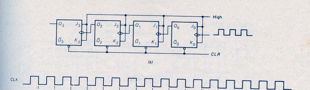
30 Counters Ring Counter Ring counter is build with D flip flops, where each word is having only one high bit. It resembles a shift left register. When CLR goes low then back to high, the initial output word is Q=0001 The first positive clock edge shifts the most significant bit(msb) into the Last Significant position, and the output word becomes Q=0010 The second positive clock edge causes another rotate left and output is Q=0100 After third positive clock edge Q=1000 and After forth positive clock edge Q=0001 To activate one of the several devices, or sequence of operation, ring counter is used.
 If CLR goes low, the register becomes Q=0000 on next")
31 Ripple Counters Ripple counter is build with 4 J K flip flops.(carry moves on the flip flop like a water ripple) If CLR goes low, the register becomes Q=0000 on next pulse Q=0001. On tenth pulse Q=1010 and so on

32
, Boka Raton, FL, USA (2012) AP Godse and DA")


33 Acknowledgement Intelligent technologies for web applications, CRC Press (Taylor & Francis Group), Boka Raton, FL, USA (2012) AP Godse and DA Godse, Digital principles and systems design, Technical publications, Pune clker.com c.htm Malvino A. P.: Digital Computer Electronics,2nd Edition, Tata McGraw, Hill Pub. Co. Ltd.,New Delhi, nzdl.org
Module -18 Flip flops
 1 Module -18 Flip flops 1. Introduction 2. Comparison of latches and flip flops. 3. Clock the trigger signal 4. Flip flops 4.1. Level triggered flip flops SR, D and JK flip flops 4.2. Edge triggered flip
COMBINATIONAL and SEQUENTIAL LOGIC CIRCUITS Hardware implementation and software design
 PH-315 COMINATIONAL and SEUENTIAL LOGIC CIRCUITS Hardware implementation and software design A La Rosa I PURPOSE: To familiarize with combinational and sequential logic circuits Combinational circuits
Chapter 4: FLIP FLOPS. (Sequential Circuits) By: Siti Sabariah Hj. Salihin ELECTRICAL ENGINEERING DEPARTMENT EE 202 : DIGITAL ELECTRONICS 1
 By: Siti Sabariah Hj. Salihin ELECTRICAL ENGINEERING DEPARTMENT EE 202 : DIGITAL ELECTRONICS 1") Chapter 4: FLIP FLOPS (Sequential Circuits) By: Siti Sabariah Hj. Salihin ELECTRICAL ENGINEERING DEPARTMENT 1 CHAPTER 4 : FLIP FLOPS Programme Learning Outcomes, PLO Upon completion of the programme, graduates
Chapter 4: FLIP FLOPS (Sequential Circuits) By: Siti Sabariah Hj. Salihin ELECTRICAL ENGINEERING DEPARTMENT 1 CHAPTER 4 : FLIP FLOPS Programme Learning Outcomes, PLO Upon completion of the programme, graduates
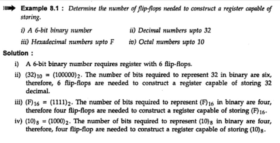
Number system: the system used to count discrete units is called number. Decimal system: the number system that contains 10 distinguished
 Number system: the system used to count discrete units is called number system Decimal system: the number system that contains 10 distinguished symbols that is 0-9 or digits is called decimal system. As
IES Digital Mock Test
 . The circuit given below work as IES Digital Mock Test - 4 Logic A B C x y z (a) Binary to Gray code converter (c) Binary to ECESS- converter (b) Gray code to Binary converter (d) ECESS- To Gray code
UNIT II: Clocked Synchronous Sequential Circuits. CpE 411 Advanced Logic Circuits Design 1
 UNIT II: Clocked Synchronous Sequential Circuits CpE 411 Advanced Logic Circuits Design 1 Unit Outline Analysis of Sequential Circuits State Tables State Diagrams Flip-flop Excitation Tables Basic Design
Fan in: The number of inputs of a logic gate can handle.
 Subject Code: 17333 Model Answer Page 1/ 29 Important Instructions to examiners: 1) The answers should be examined by key words and not as word-to-word as given in the model answer scheme. 2) The model
MAHARASHTRA STATE BOARD OF TECHNICAL EDUCATION (Autonomous) (ISO/IEC Certified) SUMMER-16 EXAMINATION Model Answer
 (ISO/IEC Certified) SUMMER-16 EXAMINATION Model Answer") Important Instructions to examiners: 1) The answers should be examined by key words and not as word-to-word as given in the model answer scheme. 2) The model answer and the answer written by candidate
Important Instructions to examiners: 1) The answers should be examined by key words and not as word-to-word as given in the model answer scheme. 2) The model answer and the answer written by candidate
Winter 14 EXAMINATION Subject Code: Model Answer P a g e 1/28
 Subject Code: 17333 Model Answer P a g e 1/28 Important Instructions to examiners: 1) The answers should be examined by key words and not as word-to-word as given in the model answer scheme. 2) The model
Spec. Instructor: Center
 PDHonline Course E379 (5 PDH) Digital Logic Circuits Volume III Spec ial Logic Circuits Instructor: Lee Layton, P.E 2012 PDH Online PDH Center 5272 Meadow Estatess Drive Fairfax, VA 22030-6658 Phone &
EXPERIMENT #5 COMBINATIONAL and SEQUENTIAL LOGIC CIRCUITS Hardware implementation and software design
 PH-315 La Rosa EXPERIMENT #5 COMINTIONL and SEUENTIL LOGIC CIRCUITS Hardware implementation and software design I PURPOSE: To familiarize with combinational and sequential logic circuits Combinational
Chapter 5 Sequential Logic Circuits Part II Hiroaki Kobayashi 7/11/2011
 Chapter 5 Sequential Logic Circuits Part II Hiroaki Kobayashi 7//2 Ver. 72 7//2 Computer Engineering What is a Sequential Circuit? A circuit consists of a combinational logic circuit and internal memory
DIGITAL ELECTRONICS QUESTION BANK
 DIGITAL ELECTRONICS QUESTION BANK Section A: 1. Which of the following are analog quantities, and which are digital? (a) Number of atoms in a simple of material (b) Altitude of an aircraft (c) Pressure
B.E. SEMESTER III (ELECTRICAL) SUBJECT CODE: X30902 Subject Name: Analog & Digital Electronics
 SUBJECT CODE: X30902 Subject Name: Analog & Digital Electronics") B.E. SEMESTER III (ELECTRICAL) SUBJECT CODE: X30902 Subject Name: Analog & Digital Electronics Sr. No. Date TITLE To From Marks Sign 1 To verify the application of op-amp as an Inverting Amplifier 2 To
B.E. SEMESTER III (ELECTRICAL) SUBJECT CODE: X30902 Subject Name: Analog & Digital Electronics Sr. No. Date TITLE To From Marks Sign 1 To verify the application of op-amp as an Inverting Amplifier 2 To
COMPUTER ORGANIZATION & ARCHITECTURE DIGITAL LOGIC CSCD211- DEPARTMENT OF COMPUTER SCIENCE, UNIVERSITY OF GHANA
 COMPUTER ORGANIZATION & ARCHITECTURE DIGITAL LOGIC LOGIC Logic is a branch of math that tries to look at problems in terms of being either true or false. It will use a set of statements to derive new true
CONTENTS Sl. No. Experiment Page No
 CONTENTS Sl. No. Experiment Page No 1a Given a 4-variable logic expression, simplify it using Entered Variable Map and realize the simplified logic expression using 8:1 multiplexer IC. 2a 3a 4a 5a 6a 1b
UNIVERSITY OF BOLTON SCHOOL OF ENGINEERING BENG (HONS) ELECTRICAL & ELECTRONICS ENGINEERING SEMESTER TWO EXAMINATION 2017/2018
 ELECTRICAL & ELECTRONICS ENGINEERING SEMESTER TWO EXAMINATION 2017/2018") UNIVERSITY OF BOLTON [EES04] SCHOOL OF ENGINEERING BENG (HONS) ELECTRICAL & ELECTRONICS ENGINEERING SEMESTER TWO EXAMINATION 2017/2018 INTERMEDIATE DIGITAL ELECTRONICS AND COMMUNICATIONS MODULE NO: EEE5002
UNIVERSITY OF BOLTON [EES04] SCHOOL OF ENGINEERING BENG (HONS) ELECTRICAL & ELECTRONICS ENGINEERING SEMESTER TWO EXAMINATION 2017/2018 INTERMEDIATE DIGITAL ELECTRONICS AND COMMUNICATIONS MODULE NO: EEE5002
Module-20 Shift Registers
 1 Module-20 Shift Registers 1. Introduction 2. Types of shift registers 2.1 Serial In Serial Out (SISO) register 2.2 Serial In Parallel Out (SIPO) register 2.3 Parallel In Parallel Out (PIPO) register
LIST OF EXPERIMENTS. KCTCET/ /Odd/3rd/ETE/CSE/LM
 LIST OF EXPERIMENTS. Study of logic gates. 2. Design and implementation of adders and subtractors using logic gates. 3. Design and implementation of code converters using logic gates. 4. Design and implementation
Electronics. Digital Electronics
 Electronics Digital Electronics Introduction Unlike a linear, or analogue circuit which contains signals that are constantly changing from one value to another, such as amplitude or frequency, digital
LOGIC DIAGRAM: HALF ADDER TRUTH TABLE: A B CARRY SUM. 2012/ODD/III/ECE/DE/LM Page No. 1
 LOGIC DIAGRAM: HALF ADDER TRUTH TABLE: A B CARRY SUM K-Map for SUM: K-Map for CARRY: SUM = A B + AB CARRY = AB 22/ODD/III/ECE/DE/LM Page No. EXPT NO: DATE : DESIGN OF ADDER AND SUBTRACTOR AIM: To design
Lecture 3: Logic circuit. Combinational circuit and sequential circuit
 Lecture 3: Logic circuit Combinational circuit and sequential circuit TRAN THI HONG HONG@IS.NAIST.JP Content Lecture : Computer organization and performance evaluation metrics Lecture 2: Processor architecture
Practical Workbook Logic Design & Switching Theory
 Practical Workbook Logic Design & Switching Theory Name : Year : Batch : Roll No : Department: Second Edition Fall 2017-18 Dept. of Computer & Information Systems Engineering NED University of Engineering
EXPERIMENT NO 1 TRUTH TABLE (1)
") EPERIMENT NO AIM: To verify the Demorgan s theorems. APPARATUS REQUIRED: THEORY: Digital logic trainer and Patch cords. The digital signals are discrete in nature and can only assume one of the two values
EPERIMENT NO AIM: To verify the Demorgan s theorems. APPARATUS REQUIRED: THEORY: Digital logic trainer and Patch cords. The digital signals are discrete in nature and can only assume one of the two values
Chapter 5 Sequential Logic Circuits Part II Hiroaki Kobayashi 6/30/2008
 Chapter 5 Sequential Logic Circuits Part II Hiroaki Kobayashi 6/3/28 6/3/28 Computer Engineering Basic Element for Sequential CircuitsSR Latch Latch Store one-bit information (two states of and ) Two inputs,
Adder Comparator 7 segment display Decoder for 7 segment display D flip flop Analysis of sequential circuits. Sequence detector
 Lecture 3 Adder Comparator 7 segment display Decoder for 7 segment display D flip flop Analysis of sequential circuits Counter Sequence detector TNGE11 Digitalteknik, Lecture 3 1 Adder TNGE11 Digitalteknik,
Laboratory Manual CS (P) Digital Systems Lab
 Digital Systems Lab") Laboratory Manual CS 09 408 (P) Digital Systems Lab INDEX CYCLE I A. Familiarization of digital ICs and digital IC trainer kit 1 Verification of truth tables B. Study of combinational circuits 2. Verification
Laboratory Manual CS 09 408 (P) Digital Systems Lab INDEX CYCLE I A. Familiarization of digital ICs and digital IC trainer kit 1 Verification of truth tables B. Study of combinational circuits 2. Verification
HIGH LOW Astable multivibrators HIGH LOW 1:1
 1. Multivibrators A multivibrator circuit oscillates between a HIGH state and a LOW state producing a continuous output. Astable multivibrators generally have an even 50% duty cycle, that is that 50% of
Linear & Digital IC Applications (BRIDGE COURSE)
") G. PULLAIAH COLLEGE OF ENGINEERING AND TECHNOLOGY Accredited by NAAC with A Grade of UGC, Approved by AICTE, New Delhi Permanently Affiliated to JNTUA, Ananthapuramu (Recognized by UGC under 2(f) and 12(B)
G. PULLAIAH COLLEGE OF ENGINEERING AND TECHNOLOGY Accredited by NAAC with A Grade of UGC, Approved by AICTE, New Delhi Permanently Affiliated to JNTUA, Ananthapuramu (Recognized by UGC under 2(f) and 12(B)
EECS 150 Homework 4 Solutions Fall 2008
 Problem 1: You have a 100 MHz clock, and need to generate 3 separate clocks at different frequencies: 20 MHz, 1kHz, and 1Hz. How many flip flops do you need to implement each clock if you use: a) a ring
Computer Architecture: Part II. First Semester 2013 Department of Computer Science Faculty of Science Chiang Mai University
 Computer Architecture: Part II First Semester 2013 Department of Computer Science Faculty of Science Chiang Mai University Outline Combinational Circuits Flips Flops Flops Sequential Circuits 204231: Computer
SRV ENGINEERING COLLEGE SEMBODAI RUKMANI VARATHARAJAN ENGINEERING COLLEGE SEMBODAI
 SEMBODAI RUKMANI VARATHARAJAN ENGINEERING COLLEGE SEMBODAI 6489 (Approved By AICTE,Newdelhi Affiliated To ANNA UNIVERSITY::Chennai) CS 62 DIGITAL ELECTRONICS LAB (REGULATION-23) LAB MANUAL DEPARTMENT OF
EECS-140/141 Introduction to Digital Logic Design Lecture 7:Sequential Logic Basics
 EECS-140/141 Introduction to Digital Logic Design Lecture 7:Sequential Logic Basics I. OVERVIEW I.A Combinational vs. Sequential Logic Combinational Logic (everything so far): Outputs depend entirely on
Serial Addition. Lecture 29 1
 Serial Addition Operations in digital computers are usually done in parallel because that is a faster mode of operation. Serial operations are slower because a datapath operation takes several clock cycles,
Lecture 20: Several Commercial Counters & Shift Register
 EE2: Switching Systems Lecture 2: Several Commercial Counters & Shift Register Prof. YingLi Tian Nov. 27, 27 Department of Electrical Engineering The City College of New York The City University of New
logic system Outputs The addition of feedback means that the state of the circuit may change with time; it is sequential. logic system Outputs
 Sequential Logic The combinational logic circuits we ve looked at so far, whether they be simple gates or more complex circuits have clearly separated inputs and outputs. A change in the input produces
Computer Systems and Networks. ECPE 170 Jeff Shafer University of the Pacific. Digital Logic
 ECPE 170 Jeff Shafer University of the Pacific Digital Logic 2 Homework Review 2.33(d) Convert 26.625 to IEEE 754 single precision floa9ng point: Format requirements for single precision (32 bit total
Department of Electronics and Communication Engineering
 Department of Electronics and Communication Engineering Sub Code/Name: BEC3L2- DIGITAL ELECTRONICS LAB Name Reg No Branch Year & Semester : : : : LIST OF EXPERIMENTS Sl No Experiments Page No Study of
Digital Logic Circuits
 Digital Logic Circuits Let s look at the essential features of digital logic circuits, which are at the heart of digital computers. Learning Objectives Understand the concepts of analog and digital signals
3.1 There are three basic logic functions from which all circuits can be designed: NOT (invert), OR, and
, OR, and") EE 2449 Experiment 3 Jack Levine and Nancy Warter-Perez, Revised 6/12/17 CALIFORNIA STATE UNIVERSITY LOS ANGELES Department of Electrical and Computer Engineering EE-2449 Digital Logic Lab EXPERIMENT 3
EE 2449 Experiment 3 Jack Levine and Nancy Warter-Perez, Revised 6/12/17 CALIFORNIA STATE UNIVERSITY LOS ANGELES Department of Electrical and Computer Engineering EE-2449 Digital Logic Lab EXPERIMENT 3
EE 42/100 Lecture 24: Latches and Flip Flops. Rev A 4/14/2010 (8:30 PM) Prof. Ali M. Niknejad
 Prof. Ali M. Niknejad") A. M. Niknejad University of California, Berkeley EE 100 / 42 Lecture 24 p. 1/15 EE 42/100 Lecture 24: Latches and Flip Flops ELECTRONICS Rev A 4/14/2010 (8:30 PM) Prof. Ali M. Niknejad University of California,
A. M. Niknejad University of California, Berkeley EE 100 / 42 Lecture 24 p. 1/15 EE 42/100 Lecture 24: Latches and Flip Flops ELECTRONICS Rev A 4/14/2010 (8:30 PM) Prof. Ali M. Niknejad University of California,
CS302 - Digital Logic Design Glossary By
 CS302 - Digital Logic Design Glossary By ABEL : Advanced Boolean Expression Language; a software compiler language for SPLD programming; a type of hardware description language (HDL) Adder : A digital
Java Bread Board Introductory Digital Electronics Exercise 2, Page 1
 Java Bread Board Introductory Digital Electronics Exercise 2, Page 1 JBB Excercise 2 The aim of this lab is to demonstrate how basic logic gates can be used to implement simple memory functions, introduce
DELD MODEL ANSWER DEC 2018
 2018 DELD MODEL ANSWER DEC 2018 Q 1. a ) How will you implement Full adder using half-adder? Explain the circuit diagram. [6] An adder is a digital logic circuit in electronics that implements addition
NORTH MAHARASHTRA UNIVERSITY, JALGAON
 , JALGAON Syllabus for F.Y.B.Sc. Semester I and II ELECTRONICS (w. e. f. June 2012) F.Y. B. Sc. Subject Electronics Syllabus Structure Semester Code Title Number of Lectures ELE-111 Paper I : Analog Electronics
LESSON PLAN. Sub Code & Name: ME2255 Electronics and Microprocessors Unit : I Branch : ME Semester: IV UNIT I SEMICONDUCTORS AND RECTIFIERS 9
 Unit : I Branch : ME Semester: IV Page 01 of 06 UNIT I SEMICONDUCTORS AND RECTIFIERS 9 Classification of solids based on energy band theory - Intrinsic semiconductors - Extrinsic semiconductors - P type
Preface... iii. Chapter 1: Diodes and Circuits... 1
 Table of Contents Preface... iii Chapter 1: Diodes and Circuits... 1 1.1 Introduction... 1 1.2 Structure of an Atom... 2 1.3 Classification of Solid Materials on the Basis of Conductivity... 2 1.4 Atomic
GATE Online Free Material
 Subject : Digital ircuits GATE Online Free Material 1. The output, Y, of the circuit shown below is (a) AB (b) AB (c) AB (d) AB 2. The output, Y, of the circuit shown below is (a) 0 (b) 1 (c) B (d) A 3.
Written exam IE1204/5 Digital Design Friday 13/
 Written exam IE204/5 Digital Design Friday 3/ 207 08.00-2.00 General Information Examiner: Ingo Sander. Teacher: Kista, William Sandqvist tel 08-7904487 Teacher: Valhallavägen, Ahmed Hemani 08-7904469
NORTH MAHARASHTRA UNIVERSITY. F.Y. B. Sc. Electronics. Syllabus. Wieth effect from june2015
 Syllabus Wieth effect from june2015 Paper- I, Semester I ELE-111: Analog Electronics I Unit- I:Introduction to Basic Circuit Components Definition and unit, Circuit Symbol, Working Principle, Classification
Code No: R Set No. 1
 Code No: R05310402 Set No. 1 1. (a) What are the parameters that are necessary to define the electrical characteristics of CMOS circuits? Mention the typical values of a CMOS NAND gate. (b) Design a CMOS
Digital Electronic Concepts
 Western Technical College 10662137 Digital Electronic Concepts Course Outcome Summary Course Information Description Career Cluster Instructional Level Total Credits 4.00 Total Hours 108.00 This course
MAHARASHTRA STATE BOARD OF TECHNICAL EDUCATION (Autonomous) (ISO/IEC Certified) MODEL ANSWER
 (ISO/IEC Certified) MODEL ANSWER") Important Instructions to examiners: 1) The answers should be examined by key words and not as word-to-word as given in the model answer scheme. 2) The model answer and the answer written by candidate
Important Instructions to examiners: 1) The answers should be examined by key words and not as word-to-word as given in the model answer scheme. 2) The model answer and the answer written by candidate
COLLEGE OF ENGINEERING, NASIK
 Pune Vidyarthi Griha s COLLEGE OF ENGINEERING, NASIK LAB MANUAL DIGITAL ELECTRONICS LABORATORY Subject Code: 2246 27-8 PUNE VIDYARTHI GRIHA S COLLEGE OF ENGINEERING,NASHIK. INDEX Batch : - Sr.No Title
! Sequential Logic. ! Timing Hazards. ! Dynamic Logic. ! Add state elements (registers, latches) ! Compute. " From state elements
 ! Compute. From state elements") ESE 570: Digital Integrated Circuits and VLSI Fundamentals Lec 19: April 2, 2019 Sequential Logic, Timing Hazards and Dynamic Logic Lecture Outline! Sequential Logic! Timing Hazards! Dynamic Logic 4 Sequential
ESE 570: Digital Integrated Circuits and VLSI Fundamentals Lec 19: April 2, 2019 Sequential Logic, Timing Hazards and Dynamic Logic Lecture Outline! Sequential Logic! Timing Hazards! Dynamic Logic 4 Sequential
Page 1. Last time we looked at: latches. flip-flop
 Last time we looked at: latches flip flops We saw that these devices hold a value depending on their inputs. A data input value is loaded into the register on the rise of the edge. Some circuits have additional
Digital Circuits Laboratory LAB no. 12. REGISTERS
 REGISTERS are sequential logic circuits that store and/or shift binary sequences. can be classified in: memory registers (with parallel load) - latch shift registers (with serial load) combined registers
HAZARDS AND PULSE MODE SEQUENTIAL CIRCUITS
 Chapter 19 HAZARDS AND PULSE MODE SEQUENTIAL CIRCUITS Ch19L5-"Digital Principles and Design", Raj Kamal, Pearson Education, 2006 1 Lesson 5 Dynamic Hazards, Essential Hazards and Pulse mode sequential
Sr. No. Instrument Specifications. TTL (Transistor-Transistor Logic) based on bipolar junction transistors
 based on bipolar junction transistors") MIT College of Engineering, Pune. Department of Electronics & Telecommunication (Electronics Lab) EXPERIMENT NO 01 TITLE OF THE EXPERIMENT: Verify four voltage and current parameters for TTL and CMOS (IC
MIT College of Engineering, Pune. Department of Electronics & Telecommunication (Electronics Lab) EXPERIMENT NO 01 TITLE OF THE EXPERIMENT: Verify four voltage and current parameters for TTL and CMOS (IC
FUNCTION OF COMBINATIONAL LOGIC CIRCUIT
 HAPTER FUNTION OF OMBINATIONAL LOGI IRUIT OUTLINE HALF-ADDER ANF FULL ADDER IRUIT -BIT PARALLEL BINARY RIPPLE ARRY ADDER -BIT PARALLEL BINARY ARRY LOOK- AHEAD ADDER BD ADDER IRUIT DEODER ENODER MULTIPLEXER
CMOS Digital Integrated Circuits Lec 11 Sequential CMOS Logic Circuits
 Lec Sequential CMOS Logic Circuits Sequential Logic In Combinational Logic circuit Out Memory Sequential The output is determined by Current inputs Previous inputs Output = f(in, Previous In) The regenerative
(CSC-3501) Lecture 6 (31 Jan 2008) Seung-Jong Park (Jay) CSC S.J. Park. Announcement
 Lecture 6 (31 Jan 2008) Seung-Jong Park (Jay) CSC S.J. Park. Announcement") Seung-Jong Park (Jay) http://www.csc.lsu.edu/~sjpark Computer Architecture (CSC-3501) Lecture 6 (31 Jan 2008) 1 Announcement 2 1 Reminder A logic circuit is composed of: Inputs Outputs Functional specification
Seung-Jong Park (Jay) http://www.csc.lsu.edu/~sjpark Computer Architecture (CSC-3501) Lecture 6 (31 Jan 2008) 1 Announcement 2 1 Reminder A logic circuit is composed of: Inputs Outputs Functional specification
CMOS Digital Integrated Circuits Analysis and Design
 CMOS Digital Integrated Circuits Analysis and Design Chapter 8 Sequential MOS Logic Circuits 1 Introduction Combinational logic circuit Lack the capability of storing any previous events Non-regenerative
Computer Architecture and Organization:
 Computer Architecture and Organization: L03: Register transfer and System Bus By: A. H. Abdul Hafez Abdul.hafez@hku.edu.tr, ah.abdulhafez@gmail.com 1 CAO, by Dr. A.H. Abdul Hafez, CE Dept. HKU Outlines
Digital Electronics Course Objectives
 Digital Electronics Course Objectives In this course, we learning is reported using Standards Referenced Reporting (SRR). SRR seeks to provide students with grades that are consistent, are accurate, and
UNIT-IV Combinational Logic
 UNIT-IV Combinational Logic Introduction: The signals are usually represented by discrete bands of analog levels in digital electronic circuits or digital electronics instead of continuous ranges represented
DIGITAL CIRCUITS AND SYSTEMS ASSIGNMENTS 1 SOLUTIONS
 DIGITAL CIRCUITS AND SYSTEMS ASSIGNMENTS 1 SOLUTIONS 1. Analog signal varies continuously between two amplitudes over the given interval of time. Between these limits of amplitude and time, the signal
Electronic Components And Circuit Analysis
 Theory /Practical Theory Semester /Annual Semester Semester No. I II Swami Ramanand Teerth Marathwada University, Nanded Syllabus B. Sc. First Year ELECTRONICS Semester System (MCQ Pattern) (To Be Implemented
EE 42/100 Lecture 24: Latches and Flip Flops. Rev B 4/21/2010 (2:04 PM) Prof. Ali M. Niknejad
 Prof. Ali M. Niknejad") A. M. Niknejad University of California, Berkeley EE 100 / 42 Lecture 24 p. 1/21 EE 42/100 Lecture 24: Latches and Flip Flops ELECTRONICS Rev B 4/21/2010 (2:04 PM) Prof. Ali M. Niknejad University of California,
A. M. Niknejad University of California, Berkeley EE 100 / 42 Lecture 24 p. 1/21 EE 42/100 Lecture 24: Latches and Flip Flops ELECTRONICS Rev B 4/21/2010 (2:04 PM) Prof. Ali M. Niknejad University of California,
Dhanalakshmi College of Engineering
 Dhanalakshmi College of Engineering Manimangalam, Tambaram, Chennai 601 301 DEPARTMENT OF ELECTRICAL AND ELECTRONICS ENGINEERING EE6311 LINEAR AND DIGITAL INTEGRATED CIRCUITS LABORATORY III SEMESTER -
6.111 Lecture # 19. Controlling Position. Some General Features of Servos: Servomechanisms are of this form:
 6.111 Lecture # 19 Controlling Position Servomechanisms are of this form: Some General Features of Servos: They are feedback circuits Natural frequencies are 'zeros' of 1+G(s)H(s) System is unstable if
DEPARTMENT OF ELECTRICAL & ELECTRONICS ENGINEERING
 DEPARTMENT OF ELECTRICAL & ELECTRONICS ENGINEERING (Regulation 2013) EE 6311 LINEAR AND DIGITAL INTEGRATED CIRCUITS LAB MANUAL 1 SYLLABUS OBJECTIVES: Working Practice in simulators / CAD Tools / Experiment
CS302 Digital Logic Design Solved Objective Midterm Papers For Preparation of Midterm Exam
 CS302 Digital Logic Design Solved Objective Midterm Papers For Preparation of Midterm Exam MIDTERM EXAMINATION 2011 (October-November) Q-21 Draw function table of a half adder circuit? (2) Answer: - Page
Lecture 02: Digital Logic Review
 CENG 3420 Lecture 02: Digital Logic Review Bei Yu byu@cse.cuhk.edu.hk CENG3420 L02 Digital Logic. 1 Spring 2017 Review: Major Components of a Computer CENG3420 L02 Digital Logic. 2 Spring 2017 Review:
E-Tec Module Part No
 E-Tec Module Part No.108227 1. Additional programs for the fischertechnik Electronics Module For fans of digital technology, these additional functions are provided in the "E-Tec module". Four additional
Dr. Nicola Nicolici COE/EE2DI4 Midterm Test #1 Oct 18, 2006
 COE/EE2DI4 Midterm Test #1 Fall 2006 Page 1 Dr. Nicola Nicolici COE/EE2DI4 Midterm Test #1 Oct 18, 2006 Instructions: This examination paper includes 10 pages and 20 multiple-choice questions starting
1 Q' 3. You are given a sequential circuit that has the following circuit to compute the next state:
 UNIVERSITY OF CALIFORNIA Department of Electrical Engineering and Computer Sciences C50 Fall 2001 Prof. Subramanian Homework #3 Due: Friday, September 28, 2001 1. Show how to implement a T flip-flop starting
CHAPTER 5 DESIGNS AND ANALYSIS OF SINGLE ELECTRON TECHNOLOGY BASED MEMORY UNITS
 208 CHAPTER 5 DESIGNS AND ANALYSIS OF SINGLE ELECTRON TECHNOLOGY BASED MEMORY UNITS 5.1 INTRODUCTION The objective of this chapter is to design and verify the single electron technology based memory circuits
Combinational Logic Circuits. Combinational Logic
 Combinational Logic Circuits The outputs of Combinational Logic Circuits are only determined by the logical function of their current input state, logic 0 or logic 1, at any given instant in time. The
0 0 Q Q Q Q
 Question 1) Flip Flops and Counters (15 points) a) Fill in the truth table for a JK flip flop. Use Q or Q to denote the previous value of Q and Q. (6 pts) J K CLK Q Q Q Q 1 1 1 1 1 1 Q Q b) In Figure 1a
Paper No. Name of the Paper Theory marks Practical marks Periods per week Semester-I I Semiconductor
 Swami Ramanand Teerth Marathwada University, Nanded B. Sc. First Year Electronics Syllabus Semester system (To be implemented from Academic Year 2009-10) Name of the Theory marks Practical marks Periods
ELECTRONICS ADVANCED SUPPLEMENTARY LEVEL
 ELECTRONICS ADVANCED SUPPLEMENTARY LEVEL AIMS The general aims of the subject are : 1. to foster an interest in and an enjoyment of electronics as a practical and intellectual discipline; 2. to develop
ENGIN 112 Intro to Electrical and Computer Engineering
 ENGIN 112 Intro to Electrical and Computer Engineering Lecture 28 Timing Analysis Overview Circuits do not respond instantaneously to input changes Predictable delay in transferring inputs to outputs Propagation
Digital Electronics. A. I can list five basic safety rules for electronics. B. I can properly display large and small numbers in proper notation,
 St. Michael Albertville High School Teacher: Scott Danielson September 2016 Content Skills Learning Targets Standards Assessment Resources & Technology CEQ: WHAT MAKES DIGITAL ELECTRONICS SO IMPORTANT
PHYSICS 536 Experiment 14: Basic Logic Circuits
 PHYSICS 5 Experiment 4: Basic Logic Circuits Several T 2 L ICs will be used to illustrate basic logic functions. Their pin connections are shown in the following sketch, which is a top view. 4 2 9 8 +5V
Introduction. BME208 Logic Circuits Yalçın İŞLER
 Introduction BME208 Logic Circuits Yalçın İŞLER islerya@yahoo.com http://me.islerya.com 1 Lecture Three hours a week (three credits) No other sections, please register this section Tuesday: 09:30 12:15
CPE/EE 427, CPE 527 VLSI Design I: Homeworks 3 & 4
 CPE/EE 427, CPE 527 VLSI Design I: Homeworks 3 & 4 1 2 3 4 5 6 7 8 9 10 Sum 30 10 25 10 30 40 10 15 15 15 200 1. (30 points) Misc, Short questions (a) (2 points) Postponing the introduction of signals
Multiplier and Accumulator Using Csla
 IOSR Journal of Electronics and Communication Engineering (IOSR-JECE) e-issn: 2278-2834,p- ISSN: 2278-8735.Volume 10, Issue 1, Ver. 1 (Jan - Feb. 2015), PP 36-44 www.iosrjournals.org Multiplier and Accumulator
! Review: Sequential MOS Logic. " SR Latch. " D-Latch. ! Timing Hazards. ! Dynamic Logic. " Domino Logic. ! Charge Sharing Setup.
 ESE 570: Digital Integrated Circuits and VLSI Fundamentals Lec 9: March 29, 206 Timing Hazards and Dynamic Logic Lecture Outline! Review: Sequential MOS Logic " SR " D-! Timing Hazards! Dynamic Logic "
EE584 Introduction to VLSI Design Final Project Document Group 9 Ring Oscillator with Frequency selector
 EE584 Introduction to VLSI Design Final Project Document Group 9 Ring Oscillator with Frequency selector Group Members Uttam Kumar Boda Rajesh Tenukuntla Mohammad M Iftakhar Srikanth Yanamanagandla 1 Table
Positive and Negative Logic
 Course: B.Sc. Applied Physical Science (Computer Science) Year & Sem.: IInd Year, Sem - IIIrd Subject: Computer Science Paper No.: IX Paper Title: Computer System Architecture Lecture No.: 4 Lecture Title:
Unit level 4 Credit value 15. Introduction. Learning Outcomes
 Unit 20: Unit code Digital Principles T/615/1494 Unit level 4 Credit value 15 Introduction While the broad field of electronics covers many aspects, it is digital electronics which now has the greatest
Course Outline Cover Page
 College of Micronesia FSM P.O. Box 159 Kolonia, Pohnpei Course Outline Cover Page Digital Electronics I VEE 135 Course Title Department and Number Course Description: This course provides the students
! Is it feasible? ! How do we decompose the problem? ! Vdd. ! Topology. " Gate choice, logical optimization. " Fanin, fanout, Serial vs.
 ESE 570: Digital Integrated Circuits and VLSI Fundamentals Design Space Exploration Lec 18: March 28, 2017 Design Space Exploration, Synchronous MOS Logic, Timing Hazards 3 Design Problem Problem Solvable!
Low Power Adiabatic Logic Design
 IOSR Journal of Electronics and Communication Engineering (IOSR-JECE) e-issn: 2278-2834,p- ISSN: 2278-8735.Volume 12, Issue 1, Ver. III (Jan.-Feb. 2017), PP 28-34 www.iosrjournals.org Low Power Adiabatic
ELECTRONIC CIRCUITS. Time: Three Hours Maximum Marks: 100
 EC 40 MODEL TEST PAPER - 1 ELECTRONIC CIRCUITS Time: Three Hours Maximum Marks: 100 Answer five questions, taking ANY TWO from Group A, any two from Group B and all from Group C. All parts of a question
S-[F] NPW-02 June All Syllabus B.Sc. [Electronics] Ist Year Semester-I & II.doc - 1 -
![S-[F] NPW-02 June All Syllabus B.Sc. [Electronics] Ist Year Semester-I & II.doc - 1 -](/thumbs/79/79759849.jpg "S-[F] NPW-02 June All Syllabus B.Sc. [Electronics] Ist Year Semester-I & II.doc - 1 -") - 1 - - 2 - - 3 - DR. BABASAHEB AMBEDKAR MARATHWADA UNIVERSITY, AURANGABAD SYLLABUS of B.Sc. FIRST & SECOND SEMESTER [ELECTRONICS (OPTIONAL)] {Effective from June- 2013 onwards} - 4 - B.Sc. Electronics
- 1 - - 2 - - 3 - DR. BABASAHEB AMBEDKAR MARATHWADA UNIVERSITY, AURANGABAD SYLLABUS of B.Sc. FIRST & SECOND SEMESTER [ELECTRONICS (OPTIONAL)] {Effective from June- 2013 onwards} - 4 - B.Sc. Electronics
EE6301 DIGITAL LOGIC CIRCUITS LT P C UNIT I NUMBER SYSTEMS AND DIGITAL LOGIC FAMILIES 9
 EE6301 DIGITAL LOGIC CIRCUITS LT P C 3 1 0 4 UNIT I NUMBER SYSTEMS AND DIGITAL LOGIC FAMILIES 9 Review of number systems, binary codes, error detection and correction codes (Parity and Hamming code)- Digital
Design of low-power, high performance flip-flops
 Int. Journal of Applied Sciences and Engineering Research, Vol. 3, Issue 4, 2014 www.ijaser.com 2014 by the authors Licensee IJASER- Under Creative Commons License 3.0 editorial@ijaser.com Research article
SIMULATION DESIGN TOOL LABORATORY MANUAL
 SHANKERSINH VAGHELA BAPU INSTITUTE OF TECHNOLOGY SIMULATION DESIGN TOOL LABORATORY MANUAL B.E. 4 th SEMESTER-2015-16 SHANKERSINH VAGHELA BAPU INSTITUTE OF TECHNOLOGY Gandhinagar-Mansa Road, PO. Vasan,