MAHARASHTRA STATE BOARD OF TECHNICAL EDUCATION (Autonomous) (ISO/IEC Certified) MODEL ANSWER
|
|
|
- Richard Stevenson
- 6 years ago
- Views:
Transcription
1 Important Instructions to examiners: 1) The answers should be examined by key words and not as word-to-word as given in the model answer scheme. 2) The model answer and the answer written by candidate may vary but the examiner may try to assess the understanding level of the candidate. 3) The language errors such as grammatical, spelling errors should not be given more Importance (Not applicable for subject English and Communication Skills). 4) While assessing figures, examiner may give credit for principal components indicated in the figure. The figures drawn by candidate and model answer may vary. The examiner may give credit for any equivalent figure drawn. 5) Credits may be given step wise for numerical problems. In some cases, the assumed constant values may vary and there may be some difference in the candidate s answers and model answer. 6) In case of some questions credit may be given by judgement on part of examiner of relevant answer based on candidate s understanding. 7) For programming language papers, credit may be given to any other program based on equivalent concept. Q. No. Sub Q.N. 1. A) i) ii) Answer Attempt any six: Draw truth table for NAND and NOR gates. Truth table of NAND and NOR gates: NANDNOR A B Y A B Y Compare analog signal with digital signal according to nature/shape of signals and application. Analog Signal Digital Signal Shape of signal Continuous in time. Can have any value in a Continuous in time. Can have only two limited range Denoted by sine waves possible values Denoted by square waves Markin g Scheme 6x2=12 Each 1M 1M each Page 1/36
2 iii) iv) v) Applications Amplifiers, Operational Amplifiers, telephones State any two Boolean laws with expression. Boolean laws: A + 1 = 1 A + 0 = A A. 1 = A A. 0 = 0 A + A = A A. A = A A+B = B+A A.B = B.A (A + B) + C = A + (B + C) (A B) C = A (B C) A (B + C) = A B + A C A + (B C) = (A + B) (A + C) Logic gates, microcontrollers, Computers Perform BCD addition for (2375) + (4933) =? Adding carry to the next four bit group State the difference between Half and Full adder. Half adder is a circuit that adds 2 binary bits. A full adder is a circuit the adds 3 bits (2 bits along with carry) Any 2 1M each Correct Each 1M Page 2/36
3 vi) vii) viii) Write any four applications of counter. Applications of counters: 1. Frequency counters 2. Digital clocks 3. Analog to digital convertors. 4. With some changes in their design, counters can be used as frequency divider circuits. The frequency divider circuit is that which divides the input frequency exactly by In time measurement. That means calculating time in timers such as electronic devices like ovens and washing machines. 6. We can design digital triangular wave generator by using counters. State application of MUX and De-MUX. Application of MUX: 1. Implementing multi output combinational logic circuit 2. Multiplexer allow the process of transmitting different type of data such as audio, video at the same time using a single transmission line. 3. In telephone network, multiple audio signals are integrated on a single line for transmission with the help of multiplexers. 5. Multiplexers are used to implement huge amount of memory into the computer, at the same time reduces the number of copper lines required to connect the memory to other parts of the computer circuit. 6. Multiplexer can be used for the transmission of data signals from the computer system of a satellite or spacecraft to the ground system using the GPS (Global Positioning System) satellites. Application of De-MUX: 1. Decoder 2. Demultiplexer is used to connect a single source to multiple destinations. 3. In an ALU circuit, the output of ALU can be stored in multiple registers or storage units with the help of demultiplexer. 4. Serial data from the incoming serial data stream is given as data input to the demultiplexer at the regular intervals. Draw symbol of J-K flip-flop and write its truth table. Symbol of flip-flop: Any four ½M each Any two applica tion 1M each Page 3/36
 i) ii) Attempt any two: List types of digital to analog converters and state specifications of ADC (any four). Types of Digital to Analog converters and specifications 1.")
4 1M J_K flipflop Truth Table: Inputs Output J n K n Q n Q n Q n Truth Table 1M 1. (B) i) ii) Attempt any two: List types of digital to analog converters and state specifications of ADC (any four). Types of Digital to Analog converters and specifications 1. Weighted resistor D to A converter 2. R 2R D to A converter Specifications of ADC: 1. Resolution 2. Accuracy 3. Conversion time 4. Linearity 5. Analog input voltage 6. Format of digital output Describe classification of memories. Classification of Memories: 4x2=8 Types Any four specific ations ½ M each Page 4/36
5 Classifi cation of Memor ies 1M Random Access Memories (RWM or RAM) In this type of memory the memory locations are organized in such a way that any memory location requires equal time for writing or reading. RAMs can be static or dynamic and can be fabricated using bipolar or Unipolar technologies. Read Only Memories (ROM) These memories are meant only for reading the information from it. The process of entering information is done outside the system where it is used. This type of memory is used to store fixed tables of functions etc. These memories are further classified on the basis of technique employed in storing information into the memory or their erasable properties. These are 1. ROM (Read Only Memory) 2. PROM (Programmable Read Only Memory) 3. EPROM (Erasable Programmable Read Only Memory) 4. EEPROM (Electrically Erasable PROM) Descrip tion 3M Programmable ROM (PROM) It can be programmed by the user. It can be programmed only once after which its contents are permanently fixed as ROM. To write data into a PROM a PROM programmer or PROM burner is used. At the time of manufacturing a blank PROM, the data is entirely made up of 1 s. The PROM programmer writes data into the PROM by applying high voltage pulses which are not encountered during normal operation. Once the PROM has been programmed in this way, its Page 5/36

6 iii) contents can never be changed. Hence PROMs are also known as One-time programmable ROMs. Erasable PROM (EPROM) It can be programmed again and again. Once programmed the EPROM is a non-volatile memory that holds stored data indefinitely. EPROM can be erased by exposure to strong ultraviolet light for about 20 minutes or longer. The programming is done with EPROM programmer which is a separate unit. EPROMs are identified by the presence of a transparent quartz window, which permits ultraviolet light during erasing. Electrically Erasable PROM (EEPROM) It is non-volatile memory which allows its entire contents or selected locations to be erased and rewritten. EEPROM need not be removed from the circuit to erased and reprogrammed. State and explain De-morgan theorems. Explan ation Theorem1: It state that the, complement of a sum is equal to product of complement Theorem2: It states that, the complement of a product is equal to sum of the complements. Page 6/36
 10 i) Binary number: ii) Octal number respectively.")
7 2. a) Attempt any four: Convert following number into its equivalent = (146.25) 10 i) Binary number: ii) Octal number respectively. i) Binary number: 4x4=16 Page 7/36
")


8 ii) Octal number: b) Draw symbol and truth table for (i) 3 i/p OR gate (ii) 2 i/p EX- NOR gate. (i) 3 i/p OR gate: 3 i/p OR gate (ii) 2 i/p EX-NOR gate. 2 i/p EX- NOR gate Page 8/36
 Draw block diagram of decimal to BCD encoder and write its truth table.")
9 c) Implement the following logic expression using 16 : 1 MUX Y = m (0, 3, 5, 6, 7, 10, 13). d) Draw block diagram of decimal to BCD encoder and write its truth table. Diagra m Block Diagram of Decimal to BCD encoder Page 9/36
 states of the")
10 Truth table e) f) Truth Table Compare combinational and sequential circuits (four points). Combinational Logic Circuits Sequential Logic Circuits Output is a function of the Output is a function of clock, present inputs (Time present inputs and the previous Independent Logic) states of the system. Do not have the ability to store data (state). Logic gates are the elementary building blocks. Independent of clock and hence does not require triggering to operate. Used mainly for Arithmetic and Boolean operations. It does not require any feedback. It simply outputs the input according to the logic designed. Have memory to store the present states that is sent as control input (enable) for the next operation. Flip flops (binary storage device) are the elementary building unit. Clocked (Triggered for operation with electronic pulses). Used for storing data (and hence used in RAM). It involves feedback from output to input that is stored in the memory for the next operation. Draw circuit diagram of successive approximation type ADC and explain its working. The comparator serves the function of the scale, the output of which is Any four points 1M each Page 10/36

11 used for setting resetting the bits at the output of the programmer/ This output is converted into equivalent analog voltage from which the offset voltage is subtracted and then applied to the inverting input terminal of the comparator. It should be noted that the offset weight was added on the side of the unknown weight, and therefore, it is to be subtracted from the known weight side for getting the equivalent effect. The outputs of the programmer will change only when the clock pulse is present. To start conversion, the programmer sets the MSB to 1 and all other bits to 0. This is converted into analog signal by the D/A converter and the comparator compares it with the analog input voltage. If the analog input voltage V a V i, the output voltage V O of the comparator is HIGH which sets the next bit also. On the other hand, if V a <V i, then V O is LOW which resets the MSB and sets the next bit. Thus, a 1 is tried in each bit of the D/A converter until the binary equivalent of the analog input voltage is obtained. Explan ation Diagra m 3. a) Successive-approximation A/D converter. Attempt any four: Perform binary subtraction using 2 s complements of following: i) (63) 10 (20) 10 ii) (34) 10 (48) 10 =? i) (63) 10 (20) 10 : 4x4=16 Page 11/36

12 Page 12/36

13 ii) (34) 10 (48) 10 =? Page 13/36
14 b) Simplify the following and realize it Y = A + AB C + A BC + ABC + AB c) Explain full adder with logic diagram and its truth table and proper expressions. It is a combinational circuit which performs the arithmetic sum of three input bits. It consists of 03 inputs and two outputs. Page 14/36


15 Explan ation & Truth table 1M k-map + express ion Logic diagra m 1M Page 15/36
16 d) Draw diagram of BCD to segment decoder using IC 7447 with truth table. Circuit diagra m Truth Table e) Describe the operation of RS Flip Flop using NAND gates only. ((Note: Consider the working of Clocked RS Flip Flop also) Page 16/36


17 Diagra m Explan ation Page 17/36
18 4. f) a) State advantages and disadvantages of (i) Ramp type ADC (ii) Dual slope type ADC. (i) Ramp type ADC: Advantages of Ramp type ADC: 1. It is very simple in construction. 2. It is easy to design. 3. It is last expensive. 4. Its speed can be adjusted by adjusting the clock frequency 5. It is faster than a dual slope ADC. Disadvantages of Ramp type ADC: 1. It is comparatively very slow. 2. The conversion time does not remain constant. 3. The conversion time can be as long as clock cycle period for high input voltages. 4. It needs longer conversion time. (ii) Dual slope type ADC: Advantages of Dual slope type ADC:: 1. It is simple and relatively inexpensive. 2. It has high conversion accuracy. 3. It is more stable and of low cost. 4. It is not affected by time, temperature and input voltage. 5. It does not require crystal oscillator for stability. 6. It is less sensitive to noise. Disadvantages of Dual slope type ADC: 1. It has large conversion time as compared to any other ADC. 2. It has very low speed of conversion. Attempt any four: Construct 16:1 multiplexer using 4:1 multiplexer. Draw diagram. Any two advant ages and disadva ntages of Ramp type ADC each 1M Any two advant ages and disadva ntages of Dual slope type ADC each 1M 4x4=16 Page 18/36


19 Correct implem entatio n b) What is race around condition? How can it be overcome? In J-K Flip Flop, when the I/p J = 1 & K = 1then the O/p of J-K flip flop is Q n compliments of previous O/p. Let Q = 0 & clock pulse is applied as Explan ation At a time interval t, the O/p will change to Q n that means the O/p now is Q = 1.Now we have J =1, K = 1 & Q = 1. After another time interval t, the O/p will again change from 1 to 0 Page 19/36
 Hence at the end of the clock pulse, when C/k=0, the value of a Q O/p is uncertain. This situation is called as race around condition.")
20 c) ANS. (Q n ) due to feedback connection. Thus the O/p oscillates back and forth between 0 to 1 for the duration of the clock pulse. (1K = 1) Hence at the end of the clock pulse, when C/k=0, the value of a Q O/p is uncertain. This situation is called as race around condition. This race around condition can be avoided by using Master Slave I-K flip flop. A Master Slave J-K flip flop is a cascade of two J-K flip flop. The feedback from the output of second flip flop is given to the input of first flip-flop as shown in fig. Draw AND, OR, NOT logic gates using any one of the universal gates and write its expressions. Correct express ions Page 20/36


21 d) Draw R-2R ladder digital to analog converter and explain its working. R -2R ladder DAC uses two resistors R & 2R. The input is applied through digitally controlled switches. Circuit diagra m Descrip tion For example if the digital input is 001 Applying Thevenins theorem at XX Page 21/36


22 Applying Thevenins theorem at yy Applying Thevenins theorem at zz Similarly for digital input 010 and 100 the equivalent voltages are VR/2 2 And VR/2 1 respectively. The equivalent resistance is 3R in each case. So the simplified circuit of 3bit R-2R ladder DAC is Page 22/36
 = - (R F /3R) (V R /2 3 ) (4b 2 + 2b 1 + b 0 ) Describe following number systems with respect to their base/radix, digits/symbols and its example.")
23 e) f) The analog output voltage for a given digital input is given by V out = - ((R F /3R) V R x b 0 /2 3 + R F /3R V R x b 1 /2 2 + R F /3R V R x b 2 /2 1 ) = - (R F /3R) (V R /2 3 ) (2 2 b b b 0 ) = - (R F /3R) (V R /2 3 ) (4b 2 + 2b 1 + b 0 ) Describe following number systems with respect to their base/radix, digits/symbols and its example. (i) Octal number (ii) Hexadecimal number. Binary Base/ Digits/symbols Example Radix Octal number 8 0, 1, 2, 3, 4, 5, 6, 7 ( ) 8 Hexadecimal 16 0, 1, 2, 3, 4, 5, number 6, 7, 8, 9, A, (3FA9.56) 16 B, C, D, E, f What is modulus counter? Design MOD-7 counter using IC Modulus of a counter. Number of states through which the counter passes during its operation. A flip flop has 02 states. Thus the group of N flip flops will have 2 n states. This means it is possible to make a module 2 n counter using n flip-flops. However it is desired to have a module m counter the no. of FF s required is determined by the following equation. m 2 N N Minimum value of N which satisfies the equation. Each Explan ation Page 23/36
 0.4V good 5V (excellent) 6 Propagation delay 10 ns 70 ns 7 Speed-power product 100 0.")
24 5. a) b) Attempt any four: Compare CMOS and TTL Logic families. Sr Parameters TTL CMOS No. 1 Basic gates NAND NOR or NAND 2 Fan-in Fan-out 10 >50 4 Power dissipation per 10mW 0.01mW gate 5 Noise margin (immunity) 0.4V good 5V (excellent) 6 Propagation delay 10 ns 70 ns 7 Speed-power product Clock rate for flip-flop 35 MHz 10 MHz 9 Available function Very large Large 10 Packing Density Lower Larger 11 Cost Low Very low. Draw and explain working of Hex to Binary encoder with truth table. Hexadecimal to Binary Encoder can be constructed by using two octal to binary encoder IC The lower 8-bits are applied to inputs of IC-1 where as higher 8-bits are applied to inputs of IC-2. The enable inputs are so connected that only one IC is enabled at a time. To achieve this EO of the IC-2 is connected to EI of IC-1. The binary outputs of both these ICs are applied as inputs to IC which is a Quad 2:1 multiplexer. GS output of IC is connected to select input of GS o/p will go low when one of its input is active. The low signal at select 4x4=16 Any 4 points 1M each Explan ation 1M Page 24/36

25 input of will select A input and produce a binary number. But is GS is high then a high signal at the select input of will select B input and produce the binary output. Truth table 1M Diagra m Page 25/36
26 c) Explain the operation 3-bit asynchronous counter with diagram. The number of states in 3-bit counter is 8 that require 3 flip-flops and QA, QB and QC are the output of the flip-flops. The output QA of the least significant F/F changes for every clock pulse. This can achieved by using the T-type F/F with TA=1. The output QB makes a transition from 0-1 or 1-0 whenever QA changes from 1 to 0. Therefore if QA is connected to the clock input of next T-type F/F FF1 with TB=1, QB goes from 1-0. Similarly QC makes a transition whenever QB goes from 1-0 and this is achieved by connecting QB to the clock input of the most significant FF2 and TC=1. Count sequen ce + wavefo rm: Diagra m Page 26/36

27 d) Draw labeled block diagram of ALU. A combinational circuit used for performing ALU operations is as shown: The block diagram of ALU is as shown. The various inputs and output control lines are: 1. A and B: 4-bit binary data input. 2. C n : Carry input. 3. Cn 4 : Carry output. 4. F: 4-bit Binary data output. 5. G: Carry Generate output. 6. P: Carry propagate output. 7. A = B: Logic 1 on this line indicates A = B. G and P outputs are used when more than one are cascaded along with Look ahead Carry Generator circuit to make arithmetic operations faster. Select inputs are used to select the specific operations out of the available. Mode control (M) is used to select between the operations. M = 0: Arithmetic Operations. M = 1: Logical Operations. Cn 4 is used for subtraction operation which indicates the sign of output. Logic 0 indicates positive result and logic 1 indicates result is negative and in its 2 s complement form. Page 27/36
28 Block diagra m e) Draw circuit diagram and explain working principle of dual- slope type ADC. The block diagram of this method is shown in Fig. It has 4 major blocks: an integrator, comparator, a binary counter & a switch driver. Diagra m Page 28/36
29 The conversion process begins at t = O with the switch S1 in position 0, hence connecting the analog voltage Va to the input of the integrator. 1 t Va The integrator output is Vo = Vadt t 0 This results in HIGH Vc, thus enabling the AND gate & the clock pulses reach the clock (CK) input terminal of the counter which was initially clear. The counter counts from to when (2 N 1) clock pulses are applied. At the next clock pulse (2 N th) the counter is cleared & Q becomes 1. This controls the state of S1 which now moves to position 1 at T1, thereby connecting V R to the input of the integrator. The output of the integrator now starts to move in the positive direction. The counter continues to count until Vo< O. As soon as Vo goes positive at T2, Vo goes LOW disabling the AND gate. The counter will stop counting in the absence of the clock pulses. Explan ation Advantages: 1.The analog input is independent of R, C and T. thus drifts in any of the components affects T1 and T2 in same proportion and ADC output remains unaffected. 2.Dual Slope ADC is capable of rejecting noise and hum. 3.Low cost. 4.Accuracy of ADC can be order of 0.05% suitable for many applications. Dis-Advantages: 1. The conversion time of this device is more than other ADC. Page 29/36
30 f) Draw proper labeled diagram of parallel in parallel out (4 bit) shift register and explain its working. Diagra m 6. a) The four bit binary input A3- A0 is applied to the data inputs D3 to D0 respectively of the four flip flops. As soon as the negative clock edge is applied the input binary bits will be loaded into the flip flops simultaneously. The loaded bits will appear simultaneously at the output side, only one clock pulse is essential to load all the bits. Attempt any two: Reduce following Boolean expression using laws and theory of Boolean algebra. Explan ation 8x2=16 8M 1. A BC ( A B)( A C) LHS ( A B)( A C) ( A B)( A C) A( A C) B( A C) A. A AC AB AC A AC AB BC A(1 C B) BC A BC RHS Page 30/36
31 b) 2. Y ( A B)( A B)( A B) [ A( A B) B( A B)]( A C) [ A. A AB AB B. B]( A C) [0 AB AB B]( A C) [ B( A A) B]( A C) ( B.1 B)( A C) ( B B)( A C) B( A C) i) Implement 1 : 16 demultiplexer using 1 : 8 demultiplexer. Diagra m Truth table Page 31/36
32 b) ii) Explain working of full substractor with circuit diagram. A full substractor is used for performing multibit substraction where the borrow from the previous bit position is available. This circuit has three inputs An (minuend), Bn (subtrahend) and Bn-1 (borrow from previous stage) and two outputs Difference (Dn) and Borrow (Cn). An Bn Bn-1 Difference Dn Carry Cn Explan ation Page 32/36
33 Diagra m c) c) i) Compare synchronous and asynchronous counter. Sr Synchronous Counter Asynchronous Counter No:. 1. All flip flops are triggered with same clock. Different clock is applied to different flip flops. 2. It is faster It is slower. 3. Deign is complex. Design is relatively easy. 4. Decoding errors are not Decoding errors are present. present. 5. Any required sequence can be designed. only ii) Design a mod-10 synchronous counter. (Note: other relevant flip flop can be used) Number of desired states = 10 Number of flip flops required= 4 [ 2 n m ] Use JK flip Flop Any 4 points 6M 6M Page 33/36


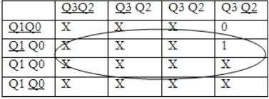
34 Draw the k maps for the respective inputs in terms of ouputs 1. J0 =1 2. K0 = 1 3. J1= Q0 Q3 4. K1= Q0 Page 34/36


35 5. J2=Q0Q1 6. K2=Q0Q1 7. J3=Q0Q1Q2 8. K3=Q0 Page 35/36

36 Page 36/36
Fan in: The number of inputs of a logic gate can handle.
 Subject Code: 17333 Model Answer Page 1/ 29 Important Instructions to examiners: 1) The answers should be examined by key words and not as word-to-word as given in the model answer scheme. 2) The model
Winter 14 EXAMINATION Subject Code: Model Answer P a g e 1/28
 Subject Code: 17333 Model Answer P a g e 1/28 Important Instructions to examiners: 1) The answers should be examined by key words and not as word-to-word as given in the model answer scheme. 2) The model
MAHARASHTRA STATE BOARD OF TECHNICAL EDUCATION (Autonomous) (ISO/IEC Certified) SUMMER-16 EXAMINATION Model Answer
 (ISO/IEC Certified) SUMMER-16 EXAMINATION Model Answer") Important Instructions to examiners: 1) The answers should be examined by key words and not as word-to-word as given in the model answer scheme. 2) The model answer and the answer written by candidate
Important Instructions to examiners: 1) The answers should be examined by key words and not as word-to-word as given in the model answer scheme. 2) The model answer and the answer written by candidate
IES Digital Mock Test
 . The circuit given below work as IES Digital Mock Test - 4 Logic A B C x y z (a) Binary to Gray code converter (c) Binary to ECESS- converter (b) Gray code to Binary converter (d) ECESS- To Gray code
Module -18 Flip flops
 1 Module -18 Flip flops 1. Introduction 2. Comparison of latches and flip flops. 3. Clock the trigger signal 4. Flip flops 4.1. Level triggered flip flops SR, D and JK flip flops 4.2. Edge triggered flip
Laboratory Manual CS (P) Digital Systems Lab
 Digital Systems Lab") Laboratory Manual CS 09 408 (P) Digital Systems Lab INDEX CYCLE I A. Familiarization of digital ICs and digital IC trainer kit 1 Verification of truth tables B. Study of combinational circuits 2. Verification
Laboratory Manual CS 09 408 (P) Digital Systems Lab INDEX CYCLE I A. Familiarization of digital ICs and digital IC trainer kit 1 Verification of truth tables B. Study of combinational circuits 2. Verification
Electronics. Digital Electronics
 Electronics Digital Electronics Introduction Unlike a linear, or analogue circuit which contains signals that are constantly changing from one value to another, such as amplitude or frequency, digital
Number system: the system used to count discrete units is called number. Decimal system: the number system that contains 10 distinguished
 Number system: the system used to count discrete units is called number system Decimal system: the number system that contains 10 distinguished symbols that is 0-9 or digits is called decimal system. As
DIGITAL ELECTRONICS QUESTION BANK
 DIGITAL ELECTRONICS QUESTION BANK Section A: 1. Which of the following are analog quantities, and which are digital? (a) Number of atoms in a simple of material (b) Altitude of an aircraft (c) Pressure
LOGIC DIAGRAM: HALF ADDER TRUTH TABLE: A B CARRY SUM. 2012/ODD/III/ECE/DE/LM Page No. 1
 LOGIC DIAGRAM: HALF ADDER TRUTH TABLE: A B CARRY SUM K-Map for SUM: K-Map for CARRY: SUM = A B + AB CARRY = AB 22/ODD/III/ECE/DE/LM Page No. EXPT NO: DATE : DESIGN OF ADDER AND SUBTRACTOR AIM: To design
Department of Electronics and Communication Engineering
 Department of Electronics and Communication Engineering Sub Code/Name: BEC3L2- DIGITAL ELECTRONICS LAB Name Reg No Branch Year & Semester : : : : LIST OF EXPERIMENTS Sl No Experiments Page No Study of
LIST OF EXPERIMENTS. KCTCET/ /Odd/3rd/ETE/CSE/LM
 LIST OF EXPERIMENTS. Study of logic gates. 2. Design and implementation of adders and subtractors using logic gates. 3. Design and implementation of code converters using logic gates. 4. Design and implementation
COMBINATIONAL CIRCUIT
 Combinational circuit is a circuit in which we combine the different gates in the circuit, for example encoder, decoder, multiplexer and demultiplexer. Some of the characteristics of combinational circuits
S-[F] NPW-02 June All Syllabus B.Sc. [Electronics] Ist Year Semester-I & II.doc - 1 -
![S-[F] NPW-02 June All Syllabus B.Sc. [Electronics] Ist Year Semester-I & II.doc - 1 -](/thumbs/79/79759849.jpg "S-[F] NPW-02 June All Syllabus B.Sc. [Electronics] Ist Year Semester-I & II.doc - 1 -") - 1 - - 2 - - 3 - DR. BABASAHEB AMBEDKAR MARATHWADA UNIVERSITY, AURANGABAD SYLLABUS of B.Sc. FIRST & SECOND SEMESTER [ELECTRONICS (OPTIONAL)] {Effective from June- 2013 onwards} - 4 - B.Sc. Electronics
- 1 - - 2 - - 3 - DR. BABASAHEB AMBEDKAR MARATHWADA UNIVERSITY, AURANGABAD SYLLABUS of B.Sc. FIRST & SECOND SEMESTER [ELECTRONICS (OPTIONAL)] {Effective from June- 2013 onwards} - 4 - B.Sc. Electronics
EXPERIMENT NO 1 TRUTH TABLE (1)
") EPERIMENT NO AIM: To verify the Demorgan s theorems. APPARATUS REQUIRED: THEORY: Digital logic trainer and Patch cords. The digital signals are discrete in nature and can only assume one of the two values
EPERIMENT NO AIM: To verify the Demorgan s theorems. APPARATUS REQUIRED: THEORY: Digital logic trainer and Patch cords. The digital signals are discrete in nature and can only assume one of the two values
Module 4: Design and Analysis of Combinational Circuits 1. Module-4. Design and Analysis of Combinational Circuits
 1 Module-4 Design and Analysis of Combinational Circuits 4.1 Motivation: This topic develops the fundamental understanding and design of adder, substractor, code converter multiplexer, demultiplexer etc
A-D and D-A Converters
 Chapter 5 A-D and D-A Converters (No mathematical derivations) 04 Hours 08 Marks When digital devices are to be interfaced with analog devices (or vice a versa), Digital to Analog converter and Analog
SRV ENGINEERING COLLEGE SEMBODAI RUKMANI VARATHARAJAN ENGINEERING COLLEGE SEMBODAI
 SEMBODAI RUKMANI VARATHARAJAN ENGINEERING COLLEGE SEMBODAI 6489 (Approved By AICTE,Newdelhi Affiliated To ANNA UNIVERSITY::Chennai) CS 62 DIGITAL ELECTRONICS LAB (REGULATION-23) LAB MANUAL DEPARTMENT OF
CS302 Digital Logic Design Solved Objective Midterm Papers For Preparation of Midterm Exam
 CS302 Digital Logic Design Solved Objective Midterm Papers For Preparation of Midterm Exam MIDTERM EXAMINATION 2011 (October-November) Q-21 Draw function table of a half adder circuit? (2) Answer: - Page
Combinational Logic Circuits. Combinational Logic
 Combinational Logic Circuits The outputs of Combinational Logic Circuits are only determined by the logical function of their current input state, logic 0 or logic 1, at any given instant in time. The
CONTENTS Sl. No. Experiment Page No
 CONTENTS Sl. No. Experiment Page No 1a Given a 4-variable logic expression, simplify it using Entered Variable Map and realize the simplified logic expression using 8:1 multiplexer IC. 2a 3a 4a 5a 6a 1b
Linear & Digital IC Applications (BRIDGE COURSE)
") G. PULLAIAH COLLEGE OF ENGINEERING AND TECHNOLOGY Accredited by NAAC with A Grade of UGC, Approved by AICTE, New Delhi Permanently Affiliated to JNTUA, Ananthapuramu (Recognized by UGC under 2(f) and 12(B)
G. PULLAIAH COLLEGE OF ENGINEERING AND TECHNOLOGY Accredited by NAAC with A Grade of UGC, Approved by AICTE, New Delhi Permanently Affiliated to JNTUA, Ananthapuramu (Recognized by UGC under 2(f) and 12(B)
1. The decimal number 62 is represented in hexadecimal (base 16) and binary (base 2) respectively as
 and binary (base 2) respectively as") BioE 1310 - Review 5 - Digital 1/16/2017 Instructions: On the Answer Sheet, enter your 2-digit ID number (with a leading 0 if needed) in the boxes of the ID section. Fill in the corresponding numbered
BioE 1310 - Review 5 - Digital 1/16/2017 Instructions: On the Answer Sheet, enter your 2-digit ID number (with a leading 0 if needed) in the boxes of the ID section. Fill in the corresponding numbered
Practical Workbook Logic Design & Switching Theory
 Practical Workbook Logic Design & Switching Theory Name : Year : Batch : Roll No : Department: Second Edition Fall 2017-18 Dept. of Computer & Information Systems Engineering NED University of Engineering
WINTER 14 EXAMINATION
 Subject Code:173 WINTER 14 EXAMINATION Model Answer Important Instructions to examiners: 1) The answers should be examined by key words and not as word-to-word as given in the model answer scheme. 2) The
Objective Questions. (a) Light (b) Temperature (c) Sound (d) all of these
 Light (b) Temperature (c) Sound (d) all of these") Objective Questions Module 1: Introduction 1. Which of the following is an analog quantity? (a) Light (b) Temperature (c) Sound (d) all of these 2. Which of the following is a digital quantity? (a) Electrical
Objective Questions Module 1: Introduction 1. Which of the following is an analog quantity? (a) Light (b) Temperature (c) Sound (d) all of these 2. Which of the following is a digital quantity? (a) Electrical
R.B.V.R.R. WOMEN S COLLEGE (AUTONOMOUS) Narayanaguda, Hyderabad. ELECTRONIC PRINCIPLES AND APPLICATIONS
 Narayanaguda, Hyderabad. ELECTRONIC PRINCIPLES AND APPLICATIONS") R.B.V.R.R. WOMEN S COLLEGE (AUTONOMOUS) Narayanaguda, Hyderabad. DEPARTMENT OF PHYSICS QUESTION BANK FOR SEMESTER V PHYSICS PAPER VI (A) ELECTRONIC PRINCIPLES AND APPLICATIONS UNIT I: SEMICONDUCTOR DEVICES
R.B.V.R.R. WOMEN S COLLEGE (AUTONOMOUS) Narayanaguda, Hyderabad. DEPARTMENT OF PHYSICS QUESTION BANK FOR SEMESTER V PHYSICS PAPER VI (A) ELECTRONIC PRINCIPLES AND APPLICATIONS UNIT I: SEMICONDUCTOR DEVICES
Digital Electronics 8. Multiplexer & Demultiplexer
 1 Module -8 Multiplexers and Demultiplexers 1 Introduction 2 Principles of Multiplexing and Demultiplexing 3 Multiplexer 3.1 Types of multiplexer 3.2 A 2 to 1 multiplexer 3.3 A 4 to 1 multiplexer 3.4 Multiplex
Sr. No. Instrument Specifications. TTL (Transistor-Transistor Logic) based on bipolar junction transistors
 based on bipolar junction transistors") MIT College of Engineering, Pune. Department of Electronics & Telecommunication (Electronics Lab) EXPERIMENT NO 01 TITLE OF THE EXPERIMENT: Verify four voltage and current parameters for TTL and CMOS (IC
MIT College of Engineering, Pune. Department of Electronics & Telecommunication (Electronics Lab) EXPERIMENT NO 01 TITLE OF THE EXPERIMENT: Verify four voltage and current parameters for TTL and CMOS (IC
UNIT-IV Combinational Logic
 UNIT-IV Combinational Logic Introduction: The signals are usually represented by discrete bands of analog levels in digital electronic circuits or digital electronics instead of continuous ranges represented
DEPARTMENT OF ELECTRICAL & ELECTRONICS ENGINEERING
 DEPARTMENT OF ELECTRICAL & ELECTRONICS ENGINEERING (Regulation 2013) EE 6311 LINEAR AND DIGITAL INTEGRATED CIRCUITS LAB MANUAL 1 SYLLABUS OBJECTIVES: Working Practice in simulators / CAD Tools / Experiment
Unit level 4 Credit value 15. Introduction. Learning Outcomes
 Unit 20: Unit code Digital Principles T/615/1494 Unit level 4 Credit value 15 Introduction While the broad field of electronics covers many aspects, it is digital electronics which now has the greatest
PROPOSED SCHEME OF COURSE WORK
 PROPOSED SCHEME OF COURSE WORK Course Details: Course Title : LINEAR AND DIGITAL IC APPLICATIONS Course Code : 13EC1146 L T P C : 4 0 0 3 Program: : B.Tech. Specialization: : Electrical and Electronics
COMBINATIONAL and SEQUENTIAL LOGIC CIRCUITS Hardware implementation and software design
 PH-315 COMINATIONAL and SEUENTIAL LOGIC CIRCUITS Hardware implementation and software design A La Rosa I PURPOSE: To familiarize with combinational and sequential logic circuits Combinational circuits
Digital Electronic Concepts
 Western Technical College 10662137 Digital Electronic Concepts Course Outcome Summary Course Information Description Career Cluster Instructional Level Total Credits 4.00 Total Hours 108.00 This course
COLLEGE OF ENGINEERING, NASIK
 Pune Vidyarthi Griha s COLLEGE OF ENGINEERING, NASIK LAB MANUAL DIGITAL ELECTRONICS LABORATORY Subject Code: 2246 27-8 PUNE VIDYARTHI GRIHA S COLLEGE OF ENGINEERING,NASHIK. INDEX Batch : - Sr.No Title
PESIT BANGALORE SOUTH CAMPUS BASIC ELECTRONICS
 PESIT BANGALORE SOUTH CAMPUS QUESTION BANK BASIC ELECTRONICS Sub Code: 17ELN15 / 17ELN25 IA Marks: 20 Hrs/ Week: 04 Exam Marks: 80 Total Hours: 50 Exam Hours: 03 Name of Faculty: Mr. Udoshi Basavaraj Module
NORTH MAHARASHTRA UNIVERSITY. F.Y. B. Sc. Electronics. Syllabus. Wieth effect from june2015
 Syllabus Wieth effect from june2015 Paper- I, Semester I ELE-111: Analog Electronics I Unit- I:Introduction to Basic Circuit Components Definition and unit, Circuit Symbol, Working Principle, Classification
ELECTRONIC CIRCUITS. Time: Three Hours Maximum Marks: 100
 EC 40 MODEL TEST PAPER - 1 ELECTRONIC CIRCUITS Time: Three Hours Maximum Marks: 100 Answer five questions, taking ANY TWO from Group A, any two from Group B and all from Group C. All parts of a question
CS302 - Digital Logic Design Glossary By
 CS302 - Digital Logic Design Glossary By ABEL : Advanced Boolean Expression Language; a software compiler language for SPLD programming; a type of hardware description language (HDL) Adder : A digital
Chapter 3 Digital Logic Structures
 Chapter 3 Digital Logic Structures Transistor: Building Block of Computers Microprocessors contain millions of transistors Intel Pentium 4 (2): 48 million IBM PowerPC 75FX (22): 38 million IBM/Apple PowerPC
CHAPTER 6 DIGITAL INSTRUMENTS
 CHAPTER 6 DIGITAL INSTRUMENTS 1 LECTURE CONTENTS 6.1 Logic Gates 6.2 Digital Instruments 6.3 Analog to Digital Converter 6.4 Electronic Counter 6.6 Digital Multimeters 2 6.1 Logic Gates 3 AND Gate The
FIRSTRANKER. 1. (a) What are the advantages of the adjustable voltage regulators over the fixed
 What are the advantages of the adjustable voltage regulators over the fixed") Code No: 07A51102 R07 Set No. 2 1. (a) What are the advantages of the adjustable voltage regulators over the fixed voltage regulators. (b) Differentiate betweenan integrator and a differentiator. [8+8]
Code No: 07A51102 R07 Set No. 2 1. (a) What are the advantages of the adjustable voltage regulators over the fixed voltage regulators. (b) Differentiate betweenan integrator and a differentiator. [8+8]
Logic Families. Describes Process used to implement devices Input and output structure of the device. Four general categories.
 Logic Families Characterizing Digital ICs Digital ICs characterized several ways Circuit Complexity Gives measure of number of transistors or gates Within single package Four general categories SSI - Small
DELD MODEL ANSWER DEC 2018
 2018 DELD MODEL ANSWER DEC 2018 Q 1. a ) How will you implement Full adder using half-adder? Explain the circuit diagram. [6] An adder is a digital logic circuit in electronics that implements addition
Preface... iii. Chapter 1: Diodes and Circuits... 1
 Table of Contents Preface... iii Chapter 1: Diodes and Circuits... 1 1.1 Introduction... 1 1.2 Structure of an Atom... 2 1.3 Classification of Solid Materials on the Basis of Conductivity... 2 1.4 Atomic
Combinational Circuits: Multiplexers, Decoders, Programmable Logic Devices
 Combinational Circuits: Multiplexers, Decoders, Programmable Logic Devices Lecture 5 Doru Todinca Textbook This chapter is based on the book [RothKinney]: Charles H. Roth, Larry L. Kinney, Fundamentals
GATE Online Free Material
 Subject : Digital ircuits GATE Online Free Material 1. The output, Y, of the circuit shown below is (a) AB (b) AB (c) AB (d) AB 2. The output, Y, of the circuit shown below is (a) 0 (b) 1 (c) B (d) A 3.
ANALOG TO DIGITAL (ADC) and DIGITAL TO ANALOG CONVERTERS (DAC)
 and DIGITAL TO ANALOG CONVERTERS (DAC)") COURSE / CODE DIGITAL SYSTEM FUNDAMENTALS (ECE421) DIGITAL ELECTRONICS FUNDAMENTAL (ECE422) ANALOG TO DIGITAL (ADC) and DIGITAL TO ANALOG CONVERTERS (DAC) Connecting digital circuitry to sensor devices
COURSE / CODE DIGITAL SYSTEM FUNDAMENTALS (ECE421) DIGITAL ELECTRONICS FUNDAMENTAL (ECE422) ANALOG TO DIGITAL (ADC) and DIGITAL TO ANALOG CONVERTERS (DAC) Connecting digital circuitry to sensor devices
INSTITUTE OF AERONAUTICAL ENGINEERING (Autonomous) Dundigal, Hyderabad
 Dundigal, Hyderabad") 1 P a g e INSTITUTE OF AERONAUTICAL ENGINEERING (Autonomous) Dundigal, Hyderabad - 500 043 ELECTRONICS AND COMMUNICATION ENGINEERING TUTORIAL QUESTION BANK Name : INTEGRATED CIRCUITS APPLICATIONS Code
1 P a g e INSTITUTE OF AERONAUTICAL ENGINEERING (Autonomous) Dundigal, Hyderabad - 500 043 ELECTRONICS AND COMMUNICATION ENGINEERING TUTORIAL QUESTION BANK Name : INTEGRATED CIRCUITS APPLICATIONS Code
Data Converters. Dr.Trushit Upadhyaya EC Department, CSPIT, CHARUSAT
 Data Converters Dr.Trushit Upadhyaya EC Department, CSPIT, CHARUSAT Purpose To convert digital values to analog voltages V OUT Digital Value Reference Voltage Digital Value DAC Analog Voltage Analog Quantity:
JEFFERSON COLLEGE COURSE SYLLABUS ETC255 INTRODUCTION TO DIGITAL CIRCUITS. 6 Credit Hours. Prepared by: Dennis Eimer
 JEFFERSON COLLEGE COURSE SYLLABUS ETC255 INTRODUCTION TO DIGITAL CIRCUITS 6 Credit Hours Prepared by: Dennis Eimer Revised Date: August, 2007 By Dennis Eimer Division of Technology Dr. John Keck, Dean
Module-20 Shift Registers
 1 Module-20 Shift Registers 1. Introduction 2. Types of shift registers 2.1 Serial In Serial Out (SISO) register 2.2 Serial In Parallel Out (SIPO) register 2.3 Parallel In Parallel Out (PIPO) register
Digital Logic Circuits
 Digital Logic Circuits Let s look at the essential features of digital logic circuits, which are at the heart of digital computers. Learning Objectives Understand the concepts of analog and digital signals
SUMMER 13 EXAMINATION Subject Code: Model Answer Page No: / N
 Important Instructions to examiners: 1) The answers should be examined by key words and not as word-to-word as given in the model answer scheme. 2) The model answer and the answer written by candidate
Classification of Digital Circuits
 Classification of Digital Circuits Combinational logic circuits. Output depends only on present input. Sequential circuits. Output depends on present input and present state of the circuit. Combinational
Dhanalakshmi College of Engineering
 Dhanalakshmi College of Engineering Manimangalam, Tambaram, Chennai 601 301 DEPARTMENT OF ELECTRICAL AND ELECTRONICS ENGINEERING EE6311 LINEAR AND DIGITAL INTEGRATED CIRCUITS LABORATORY III SEMESTER -
B.C.A 2017 DIGITAL ELECTRONICS BCA104T MODULE SPECIFICATION SHEET. Course Outline
 Course Outline B.C.A 2017 DIGITAL ELECTRONICS BCA104T MODULE SPECIFICATION SHEET The purpose of the course is to teach principles of digital electronics. This course covers varieties of topics including
Chapter 2 Signal Conditioning, Propagation, and Conversion
 09/0 PHY 4330 Instrumentation I Chapter Signal Conditioning, Propagation, and Conversion. Amplification (Review of Op-amps) Reference: D. A. Bell, Operational Amplifiers Applications, Troubleshooting,
Course Outline Cover Page
 College of Micronesia FSM P.O. Box 159 Kolonia, Pohnpei Course Outline Cover Page Digital Electronics I VEE 135 Course Title Department and Number Course Description: This course provides the students
ELECTRONICS ADVANCED SUPPLEMENTARY LEVEL
 ELECTRONICS ADVANCED SUPPLEMENTARY LEVEL AIMS The general aims of the subject are : 1. to foster an interest in and an enjoyment of electronics as a practical and intellectual discipline; 2. to develop
Paper No. Name of the Paper Theory marks Practical marks Periods per week Semester-I I Semiconductor
 Swami Ramanand Teerth Marathwada University, Nanded B. Sc. First Year Electronics Syllabus Semester system (To be implemented from Academic Year 2009-10) Name of the Theory marks Practical marks Periods
Lecture 02: Digital Logic Review
 CENG 3420 Lecture 02: Digital Logic Review Bei Yu byu@cse.cuhk.edu.hk CENG3420 L02 Digital Logic. 1 Spring 2017 Review: Major Components of a Computer CENG3420 L02 Digital Logic. 2 Spring 2017 Review:
NUMBER SYSTEM AND CODES
 NUMBER SYSTEM AND CODES INTRODUCTION:- The term digital refers to a process that is achieved by using discrete unit. In number system there are different symbols and each symbol has an absolute value and
R & D Electronics DIGITAL IC TRAINER. Model : DE-150. Feature: Object: Specification:
 DIGITAL IC TRAINER Model : DE-150 Object: To Study the Operation of Digital Logic ICs TTL and CMOS. To Study the All Gates, Flip-Flops, Counters etc. To Study the both the basic and advance digital electronics
B.E. SEMESTER III (ELECTRICAL) SUBJECT CODE: X30902 Subject Name: Analog & Digital Electronics
 SUBJECT CODE: X30902 Subject Name: Analog & Digital Electronics") B.E. SEMESTER III (ELECTRICAL) SUBJECT CODE: X30902 Subject Name: Analog & Digital Electronics Sr. No. Date TITLE To From Marks Sign 1 To verify the application of op-amp as an Inverting Amplifier 2 To
B.E. SEMESTER III (ELECTRICAL) SUBJECT CODE: X30902 Subject Name: Analog & Digital Electronics Sr. No. Date TITLE To From Marks Sign 1 To verify the application of op-amp as an Inverting Amplifier 2 To
Level 6 Graduate Diploma in Engineering Electro techniques
 9210-137 Level 6 Graduate Diploma in Engineering Electro techniques Sample Paper You should have the following for this examination one answer book non-programmable calculator pen, pencil, ruler, drawing
Digital Applications (CETT 1415) Credit: 4 semester credit hours (3 hours lecture, 4 hours lab) Prerequisite: CETT 1403 & CETT 1405
 Credit: 4 semester credit hours (3 hours lecture, 4 hours lab) Prerequisite: CETT 1403 & CETT 1405") Digital Applications () Credit: 4 semester credit hours (3 hours lecture, 4 hours lab) Prerequisite: CETT 1403 & CETT 1405 Course Description This course covers digital techniques and numbering systems,
Digital Applications () Credit: 4 semester credit hours (3 hours lecture, 4 hours lab) Prerequisite: CETT 1403 & CETT 1405 Course Description This course covers digital techniques and numbering systems,
Asst. Prof. Thavatchai Tayjasanant, PhD. Power System Research Lab 12 th Floor, Building 4 Tel: (02)
") 2145230 Aircraft Electricity and Electronics Asst. Prof. Thavatchai Tayjasanant, PhD Email: taytaycu@gmail.com aycu@g a co Power System Research Lab 12 th Floor, Building 4 Tel: (02) 218-6527 1 Chapter
2145230 Aircraft Electricity and Electronics Asst. Prof. Thavatchai Tayjasanant, PhD Email: taytaycu@gmail.com aycu@g a co Power System Research Lab 12 th Floor, Building 4 Tel: (02) 218-6527 1 Chapter
NORTH MAHARASHTRA UNIVERSITY, JALGAON
 , JALGAON Syllabus for F.Y.B.Sc. Semester I and II ELECTRONICS (w. e. f. June 2012) F.Y. B. Sc. Subject Electronics Syllabus Structure Semester Code Title Number of Lectures ELE-111 Paper I : Analog Electronics
Level 6 Graduate Diploma in Engineering Electronics and telecommunications
 9210-116 Level 6 Graduate Diploma in Engineering Electronics and telecommunications Sample Paper You should have the following for this examination one answer book non-programmable calculator pen, pencil,
the elektor datasheet collection
 the elektor datasheet collection LM117 LM136 LM137 L200 LM236 LM317 1,2...37 V/1,5 A Shunt regulator 2,5 V -1,2...-37 V/1,5 A 2,8...36 V/2 A Shunt regulator 2,5 V 1,2...37 V/1,5 A LM320LZ-12 Fixed voltage
Code No: R Set No. 1
 Code No: R05310402 Set No. 1 1. (a) What are the parameters that are necessary to define the electrical characteristics of CMOS circuits? Mention the typical values of a CMOS NAND gate. (b) Design a CMOS
In this lecture: Lecture 8: ROM & Programmable Logic Devices
 In this lecture: Lecture 8: ROM Programmable Logic Devices Dr Pete Sedcole Department of EE Engineering Imperial College London http://caseeicacuk/~nps/ (Floyd, 3 5, 3) (Tocci 2, 24, 25, 27, 28, 3 34)
Digital Electronics Course Objectives
 Digital Electronics Course Objectives In this course, we learning is reported using Standards Referenced Reporting (SRR). SRR seeks to provide students with grades that are consistent, are accurate, and
UNIT III. Designing Combinatorial Circuits. Adders
 UNIT III Designing Combinatorial Circuits The design of a combinational circuit starts from the verbal outline of the problem and ends with a logic circuit diagram or a set of Boolean functions from which
Brought to you by. Priti Srinivas Sajja. PS01CMCA02 Course Content. Tutorial Practice Material. Acknowldgement References. Website pritisajja.
 Brought to you by Priti Srinivas Sajja PS01CMCA02 Course Content Tutorial Practice Material Acknowldgement References Website pritisajja.info Multiplexer Means many into one, also called data selector
 DHANALAKSHMI COLLEGE OF ENGINEERING MANIMANGALAM. TAMBARAM, CHENNAI B.E. ELECTRICAL AND ELECTRONICS ENGINEERING III SEMESTER EE6311 Linear and Digital Integrated Circuits Laboratory LABORATORY MANUAL CLASS:
MAHARASHTRA STATE BOARD OF TECHNICAL EDUCATION (Autonomous) (ISO/IEC Certified) Subject Code : SUMMER 15 EXAMINATION Model Answer
 (ISO/IEC Certified) Subject Code : SUMMER 15 EXAMINATION Model Answer") Important Instructions to examiners: 1) The answers should be examined by key words and not as word-to-word as given in the model answer scheme. 2) The model answer and the answer written by candidate
Important Instructions to examiners: 1) The answers should be examined by key words and not as word-to-word as given in the model answer scheme. 2) The model answer and the answer written by candidate
Spec. Instructor: Center
 PDHonline Course E379 (5 PDH) Digital Logic Circuits Volume III Spec ial Logic Circuits Instructor: Lee Layton, P.E 2012 PDH Online PDH Center 5272 Meadow Estatess Drive Fairfax, VA 22030-6658 Phone &
HIGH LOW Astable multivibrators HIGH LOW 1:1
 1. Multivibrators A multivibrator circuit oscillates between a HIGH state and a LOW state producing a continuous output. Astable multivibrators generally have an even 50% duty cycle, that is that 50% of
DEPARTMENT OF ELECTRICAL & ELECTRONICS ENGINEERING. JNTU World COURSE: LINEAR AND DIGITAL IC APPLICATIONS LECTURE NOTES
 DEPARTMENT OF ELECTRICAL & ELECTRONICS ENGINEERING COURSE: LINEAR AND DIGITAL IC APPLICATIONS LECTURE NOTES Downloaded From (http://(http:// )(http:// ) INDEX S. NO. CONTENT PAGE NO. 1 UNIT I: INTEGRATED
GUJARAT TECHNOLOGICAL UNIVERSITY, AHMEDABAD, GUJARAT COURSE CURRICULUM. Course Title: Digital Electronics (Code: )
") GUJARAT TECHNOLOGICAL UNIVERSITY, AHMEDABAD, GUJARAT COURSE CURRICULUM Course Title: Digital Electronics (Code: 3322402) Diploma Programmes in which this course is offered Semester in which offered Power
GUJARAT TECHNOLOGICAL UNIVERSITY, AHMEDABAD, GUJARAT COURSE CURRICULUM Course Title: Digital Electronics (Code: 3322402) Diploma Programmes in which this course is offered Semester in which offered Power
Function Table of an Odd-Parity Generator Circuit
 Implementation of an Odd-Parity Generator Circuit The first step in implementing any circuit is to represent its operation in terms of a Truth or Function table. The function table for an 8-bit data as
Electronic Components And Circuit Analysis
 Theory /Practical Theory Semester /Annual Semester Semester No. I II Swami Ramanand Teerth Marathwada University, Nanded Syllabus B. Sc. First Year ELECTRONICS Semester System (MCQ Pattern) (To Be Implemented
Unit 3. Logic Design
 EE 2: Digital Logic Circuit Design Dr Radwan E Abdel-Aal, COE Logic and Computer Design Fundamentals Unit 3 Chapter Combinational 3 Combinational Logic Logic Design - Introduction to Analysis & Design
UNIVERSITY OF BOLTON SCHOOL OF ENGINEERING BENG (HONS) ELECTRICAL & ELECTRONICS ENGINEERING SEMESTER TWO EXAMINATION 2017/2018
 ELECTRICAL & ELECTRONICS ENGINEERING SEMESTER TWO EXAMINATION 2017/2018") UNIVERSITY OF BOLTON [EES04] SCHOOL OF ENGINEERING BENG (HONS) ELECTRICAL & ELECTRONICS ENGINEERING SEMESTER TWO EXAMINATION 2017/2018 INTERMEDIATE DIGITAL ELECTRONICS AND COMMUNICATIONS MODULE NO: EEE5002
UNIVERSITY OF BOLTON [EES04] SCHOOL OF ENGINEERING BENG (HONS) ELECTRICAL & ELECTRONICS ENGINEERING SEMESTER TWO EXAMINATION 2017/2018 INTERMEDIATE DIGITAL ELECTRONICS AND COMMUNICATIONS MODULE NO: EEE5002
Electronics II Physics 3620 / 6620
 Electronics II Physics 3620 / 6620 Feb 09, 2009 Part 1 Analog-to-Digital Converters (ADC) 2/8/2009 1 Why ADC? Digital Signal Processing is more popular Easy to implement, modify, Low cost Data from real
COMPUTER ORGANIZATION & ARCHITECTURE DIGITAL LOGIC CSCD211- DEPARTMENT OF COMPUTER SCIENCE, UNIVERSITY OF GHANA
 COMPUTER ORGANIZATION & ARCHITECTURE DIGITAL LOGIC LOGIC Logic is a branch of math that tries to look at problems in terms of being either true or false. It will use a set of statements to derive new true
Serial Addition. Lecture 29 1
 Serial Addition Operations in digital computers are usually done in parallel because that is a faster mode of operation. Serial operations are slower because a datapath operation takes several clock cycles,
16 Multiplexers and De-multiplexers using gates and ICs. (74150, 74154)
") 16 Multiplexers and De-multiplexers using gates and ICs. (74150, 74154) Aim: To design multiplexers and De-multiplexers using gates and ICs. (74150, 74154) Components required: Digital IC Trainer kit,
16 Multiplexers and De-multiplexers using gates and ICs. (74150, 74154) Aim: To design multiplexers and De-multiplexers using gates and ICs. (74150, 74154) Components required: Digital IC Trainer kit,
1 Signals and systems, A. V. Oppenhaim, A. S. Willsky, Prentice Hall, 2 nd edition, FUNDAMENTALS. Electrical Engineering. 2.
 1 Signals and systems, A. V. Oppenhaim, A. S. Willsky, Prentice Hall, 2 nd edition, 1996. FUNDAMENTALS Electrical Engineering 2.Processing - Analog data An analog signal is a signal that varies continuously.
VIVEKANAND COLLEGE (AUTONOMOUS), KOLHAPUR B.
, KOLHAPUR B.") Education for knowledge, science and culture - Shikshanmaharshi Dr. Bapuji Salunkhe Shri Swami Vivekanand Shikshan Sanstha s VIVEKANAND COLLEGE (AUTONOMOUS), KOLHAPUR B. Sc. Part I (Computer science Entire)
Education for knowledge, science and culture - Shikshanmaharshi Dr. Bapuji Salunkhe Shri Swami Vivekanand Shikshan Sanstha s VIVEKANAND COLLEGE (AUTONOMOUS), KOLHAPUR B. Sc. Part I (Computer science Entire)
Digital Electronics. A. I can list five basic safety rules for electronics. B. I can properly display large and small numbers in proper notation,
 St. Michael Albertville High School Teacher: Scott Danielson September 2016 Content Skills Learning Targets Standards Assessment Resources & Technology CEQ: WHAT MAKES DIGITAL ELECTRONICS SO IMPORTANT
CMOS Digital Integrated Circuits Analysis and Design
 CMOS Digital Integrated Circuits Analysis and Design Chapter 8 Sequential MOS Logic Circuits 1 Introduction Combinational logic circuit Lack the capability of storing any previous events Non-regenerative
"Education for Knowledge, Science and Culture" - Shikshanmaharshi Dr. Bapuji Salunkhe Shri Swami Vivekanand Shikshan Sanstha's
 "Education for Knowledge, Science and Culture" - Shikshanmaharshi Dr. Bapuji Salunkhe Shri Swami Vivekanand Shikshan Sanstha's VIVEKANAND COLLEGE (AUTONOMOUS), KOLHAPUR. B. Sc. Part I CBCS Syllabus with
Digital Applications (CETT 1415) Credit: 4 semester credit hours (3 hours lecture, 4 hours lab) Prerequisite: CETT 1403 & CETT 1405
 Credit: 4 semester credit hours (3 hours lecture, 4 hours lab) Prerequisite: CETT 1403 & CETT 1405") Digital Applications (CETT 1415) Credit: 4 semester credit hours (3 hours lecture, 4 hours lab) Prerequisite: CETT 1403 & CETT 1405 Course Description This course covers digital techniques and numbering
Digital Applications (CETT 1415) Credit: 4 semester credit hours (3 hours lecture, 4 hours lab) Prerequisite: CETT 1403 & CETT 1405 Course Description This course covers digital techniques and numbering
Positive and Negative Logic
 Course: B.Sc. Applied Physical Science (Computer Science) Year & Sem.: IInd Year, Sem - IIIrd Subject: Computer Science Paper No.: IX Paper Title: Computer System Architecture Lecture No.: 4 Lecture Title:
Lab 2 Revisited Exercise
 Lab 2 Revisited Exercise +15V 100k 1K 2N2222 Wire up led display Note the ground leads LED orientation 6.091 IAP 2008 Lecture 3 1 Comparator, Oscillator +5 +15 1k 2 V- 7 6 Vin 3 V+ 4 V o Notice that power
Chapter 4: FLIP FLOPS. (Sequential Circuits) By: Siti Sabariah Hj. Salihin ELECTRICAL ENGINEERING DEPARTMENT EE 202 : DIGITAL ELECTRONICS 1
 By: Siti Sabariah Hj. Salihin ELECTRICAL ENGINEERING DEPARTMENT EE 202 : DIGITAL ELECTRONICS 1") Chapter 4: FLIP FLOPS (Sequential Circuits) By: Siti Sabariah Hj. Salihin ELECTRICAL ENGINEERING DEPARTMENT 1 CHAPTER 4 : FLIP FLOPS Programme Learning Outcomes, PLO Upon completion of the programme, graduates
Chapter 4: FLIP FLOPS (Sequential Circuits) By: Siti Sabariah Hj. Salihin ELECTRICAL ENGINEERING DEPARTMENT 1 CHAPTER 4 : FLIP FLOPS Programme Learning Outcomes, PLO Upon completion of the programme, graduates