Functional Diagram HCPL-2400 V E V O 5 GND TRUTH TABLE (POSITIVE LOGIC) OUTPUT L Z Z
|
|
|
- Miles Robinson
- 6 years ago
- Views:
Transcription
1 20 MBd High CMR Logic Gate Optocouplers Technical Data HCPL-2400 HCPL-2430 Features High Speed: 40 MBd Typical Data Rate High Common Mode Rejection: HCPL-2400: 10 kv/µs at V CM = 300 V (Typical) AC Performance Guaranteed over Temperature High Speed AlGaAs Emitter Compatible with TTL, STTL, LSTTL, and HCMOS Logic Families Totem Pole and Tri State Output (No Pull Up Resistor Required) Safety Approval UL Recognized 3750 V rms for 1 minute per UL1577 IEC/EN/DIN EN Approved with V IORM = 630 V peak (Option 060) for HCPL-2400 CSA Approved High Power Supply Noise Immunity MIL-PRF Hermetic Version Available (HCPL- 5400/1 and HCPL-5430/1) Applications Isolation of High Speed Logic Systems Computer-Peripheral Interfaces Switching Power Supplies Isolated Bus Driver (Networking Applications) Ground Loop Elimination High Speed Disk Drive I/O Digital Isolation for A/D, D/A Conversion Pulse Transformer Replacement Functional Diagram ANODE CATHODE 1 NC 2 3 HCPL-2400 V CC 8 4 NC 5 GND TRUTH TABLE (POSITIVE LOGIC) LED ENABLE ON L OFF L ON H OFF H 7 6 OUTPUT L H Z Z V E V O Description The HCPL-2400 and HCPL-2430 high speed optocouplers combine an 820 nm AlGaAs light emitting diode with a high speed photodetector. This combination results in very high data rate capability and low input current. The totem pole output (HCPL- 2430) or three state output (HCPL-2400) eliminates the need for a pull up resistor and allows for direct drive of data buses. ANODE 1 CATHODE 1 CATHODE 2 ANODE HCPL TRUTH TABLE (POSITIVE LOGIC) LED ON OFF OUTPUT L H 7 V O1 6 V CC V O2 GND A 0.1 µf bypass capacitor must be connected between pins 5 and 8. CAUTION: It is advised that normal static precautions be taken in handling and assembly of this component to prevent damage and/or degradation which may be induced by ESD.
2 2 The detector has optical receiver input stage with built-in Schmitt trigger to provide logic compatible waveforms, eliminating the need for additional waveshaping. The hysteresis provides differential mode noise immunity and minimizes the potential for output signal chatter. The electrical and switching characteristics of the HCPL-2400 and HCPL-2430 are guaranteed over the temperature range of 0 C to 70 C. These optocouplers are compatible with TTL, STTL, LSTTL, and HCMOS logic families. When Schottky type TTL devices (STTL) are used, a data rate performance of 20 MBd over temperature is guaranteed when using the application circuit of Figure 13. Typical data rates are 40 MBd. Selection Guide 8-Pin DIP (300 Mil) Minimum CMR Single Dual Minimum Input Maximum Channel Channel dv/dt V CM On Current Propagation Delay Hermetic Package Package (V/µs) (V) (ma) (ns) Package HCPL HCPL HCPL-540X* HCPL-543X* HCPL-643X* *Technical data for the Hermetic HCPL-5400/01, HCPL-5430/31, and HCPL-6430/31 are on separate Agilent publications. Ordering Information Specify Part Number followed by Option Number (if desired). Example: HCPL-2400#XXX 060 = IEC/EN/DIN EN V IORM = 630 V peak Option* 300 = Gull Wing Surface Mount Option 500 = Tape and Reel Packaging Option HCPL-2400-XXXE = Lead Free Option *For HCPL-2400 only. Schematic I CC V CC 8 2 ANODE + I F I CC I E I O 8 V CC 7 V E 6 V O 1 I F1 + V F1 2 I O V O1 7 V F CATHODE 3 TRUTH TABLE (POSITIVE LOGIC) 5 GND 3 V F2 + 4 I F2 SHIELD I O V O2 6 5 GND LED ON OFF ON OFF ENABLE L L H H OUTPUT L H Z Z TRUTH TABLE (POSITIVE LOGIC) LED ON OFF OUTPUT L H
3 UR 3 Package Outline Drawings 8-Pin DIP Package (HCPL-2400, HCPL-2430) 9.65 ± 0.25 (0.380 ± 0.010) 7.62 ± 0.25 (0.300 ± 0.010) TYPE NUMBER 8 7 A XXXXZ 6 5 OPTION CODE* DATE CODE 6.35 ± 0.25 (0.250 ± 0.010) YYWW UL RECOGNITION 1.19 (0.047) MAX ± 0.13 (0.140 ± 0.005) 1.78 (0.070) MAX (0.185) MAX. 5 TYP ( ) ) ± (0.043 ± 0.013) 0.51 (0.020) MIN (0.115) MIN. DIMENSIONS IN MILLIMETERS AND (INCHES). *MARKING CODE LETTER FOR OPTION NUMBERS. "V" = OPTION 060 OPTION NUMBERS 300 AND 500 NOT MARKED (0.025) MAX. NOTE: FLOATING LEAD PROTRUSION IS 0.25 mm (10 mils) MAX ± 0.25 (0.100 ± 0.010) 8-Pin DIP Package with Gull Wing Surface Mount Option 300 (HCPL-2400, HCPL-2430) 9.65 ± 0.25 (0.380 ± 0.010) LAND PATTERN RECOMMENDATION (0.040) ± 0.25 (0.250 ± 0.010) 10.9 (0.430) (0.050) 2.0 (0.080) 1.19 (0.047) MAX (0.070) MAX ± 0.13 (0.140 ± 0.005) 9.65 ± 0.25 (0.380 ± 0.010) 7.62 ± 0.25 (0.300 ± 0.010) ( ) ) ± (0.043 ± 0.013) ± (0.100) (0.025 ± 0.005) BSC DIMENSIONS IN MILLIMETERS (INCHES). LEAD COPLANARITY = 0.10 mm (0.004 INCHES) ± 0.25 (0.025 ± 0.010) 12 NOM. NOTE: FLOATING LEAD PROTRUSION IS 0.25 mm (10 mils) MAX.
4 4 Solder Reflow Thermal Profile TEMPERATURE ( C) ROOM TEMPERATURE PREHEATING RATE 3 C + 1 C/ 0.5 C/SEC. REFLOW HEATING RATE 2.5 C ± 0.5 C/SEC. 160 C 150 C 140 C 3 C + 1 C/ 0.5 C 2.5 C ± 0.5 C/SEC. PREHEATING TIME 150 C, SEC. Recommended Pb-Free IR Profile TEMPERATURE T p /-5 C T L 217 C RAMP-UP 3 C/SEC. MAX. T smax C T smin PEAK TEMP. 245 C 30 SEC. 30 SEC. 50 SEC. PEAK TEMP. 240 C SOLDERING TIME 200 C PEAK TEMP. 230 C TIGHT TYPICAL LOOSE TIME (SECONDS) t s PREHEAT 60 to 180 SEC. t p t L TIME WITHIN 5 C of ACTUAL PEAK TEMPERATURE SEC. RAMP-DOWN 6 C/SEC. MAX. 60 to 150 SEC. Regulatory Information The HCPL-24XX has been approved by the following organizations: VDE Approved according to VDE 0884/06.92 (Option 060 only). UL Recognized under UL 1577, Component Recognition Program, File E IEC/EN/DIN EN Approved under: IEC : A1:2002 EN : A1:2002 DIN EN (VDE 0884 Teil 2): (Option 060 only) 25 t 25 C to PEAK TIME NOTES: THE TIME FROM 25 C to PEAK TEMPERATURE = 8 MINUTES MAX. T smax = 200 C, T smin = 150 C Insulation and Safety Related Specifications Parameter Symbol Value Units Conditions Minimum External L(101) 7.1 mm Measured from input terminals to output Air Gap (External terminals, shortest distance through air. Clearance) Minimum External L(102) 7.4 mm Measured from input terminals to output Tracking (External terminals, shortest distance path along body. Creepage) Minimum Internal 0.08 mm Through insulation distance, conductor to Plastic Gap conductor, usually the direct distance between the (Internal Clearance) photoemitter and photodetector inside the optocoupler cavity. Tracking Resistance CTI 200 Volts DIN IEC 112/VDE 0303 Part 1 (Comparative Tracking Index) Isolation Group IIIa Material Group (DIN VDE 0110, 1/89, Table 1) Option surface mount classification is Class A in accordance with CECC
5 5 IEC/EN/DIN EN Insulation Related Characteristics (HCPL-2400 OPTION 060 ONLY) Description Symbol Characteristic Units Installation classification per DIN VDE 0110/1.89, Table 1 for rated mains voltage 300 V rms I-IV for rated mains voltage 450 V rms I-III Climatic Classification 55/85/21 Pollution Degree (DIN VDE 0110/1.89) 2 Maximum Working Insulation Voltage V IORM 630 V peak Input to Output Test Voltage, Method b* V IORM x = V PR, 100% Production Test with t m = 1 sec, V PR 1181 V peak Partial Discharge < 5 pc Input to Output Test Voltage, Method a* V IORM x 1.5 = V PR, Type and sample test, V PR 945 V peak t m = 60 sec, Partial Discharge < 5 pc Highest Allowable Overvoltage* (Transient Overvoltage, t ini = 10 sec) V IOTM 6000 V peak Safety Limiting Values (Maximum values allowed in the event of a failure, also see Figure 12, Thermal Derating curve.) Case Temperature T S 175 C Input Current I S,INPUT 230 ma Output Power P S,OUTPUT 600 mw Insulation Resistance at T S, V IO = 500 V R S 10 9 Ω *Refer to the front of the optocoupler section of the current catalog, under Product Safety Regulations section IEC/EN/DIN EN for a detailed description. Note: Isolation characteristics are guaranteed only within the safety maximum ratings which must ben ensured by protective circuits in application.
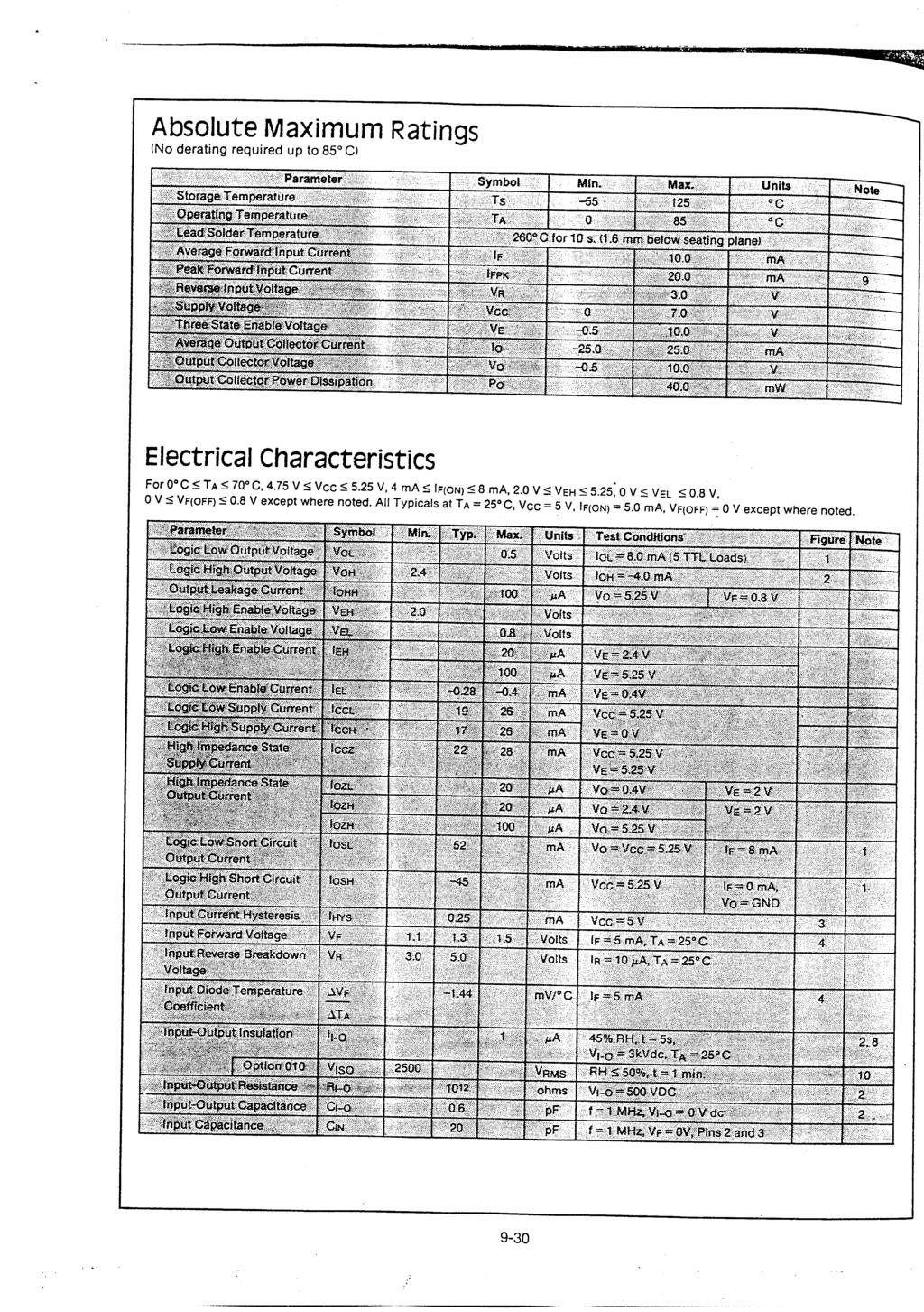
6 6 Absolute Maximum Ratings (No derating required up to 70 C) Parameter Symbol Minimum Maximum Units Note Storage Temperature T S C Operating Temperature T A C Average Forward Input Current I F(AVG) 10 ma Peak Forward Input Current I FPK 20 ma 12 Reverse Input Voltage V R 2 V Three State Enable Voltage V E V (HCPL-2400 Only) Supply Voltage V CC 0 7 V Average Output Collector Current I O ma Output Collector Voltage V O V Output Voltage V O V Output Collector Power Dissipation P O 40 mw (Each Channel) Total Package Power Dissipation P T 350 mw (Each Channel) Lead Solder Temperature 260 C for 10 sec., 1.6 mm below seating plane (for Through Hole Devices) Reflow Temperature Profile See Package Outline Drawings section (Option #300) Recommended Operating Conditions Parameter Symbol Minimum Maximum Units Power Supply Voltage V CC V Forward Input Current (ON) I F(ON) 4 8 ma Forward Input Voltage (OFF) V F(OFF) 0.8 V Fan Out N 5 TTL Loads Enable Voltage (Low) V EL V HCPL-2400 Only) Enable Voltage (High) V EH 2 V CC V HCPL-2400 Only) Operating Temperature T A 0 70 C
7 7 Electrical Specifications 0 C T A 70 C, 4.75 V V CC 5.25 V, 4 ma I F(ON) 8 ma, 0 V V F(OFF) 0.8 V. All typicals at T A =25 C, V CC = 5 V, I F(ON) = 6.0 ma, V F(OFF) = 0 V, except where noted. See Note 11. Device Parameter Symbol HCPL- Min. Typ.* Max. Units Test Conditions Fig. Note Logic Low Output Voltage V OL 0.5 V I OL = 8.0 ma (5 TTL Loads) 1 Logic High Output V OH 2.4 V I OH = -4.0 ma 2 Voltage 2.7 I OH = -0.4 ma Output Leakage Current I OHH 100 µa V O = 5.25 V, V F = 0.8 V Logic High Enable Current V EH V Logic Low Enable Voltage V EL V Logic High Enable I EH µa V E = 2.4 V Current 100 V E = 5.25 V Logic Low Enable Current I EL ma V E = 0.4 V Logic Low Supply Current I CCL ma V CC = 5.25 V, V E = 0 V, I O = Open V CC = 5.25 V, I O = Open Logic High Supply I CCH ma V CC = 5.25 V, V E = 0 V, Current I O = Open V CC = 5.25 V, I O = Open High Impedance State I CCZ ma V CC = 5.25 V, V E = 5.25 V Supply Current High Impedance State I OZL µa V O = 0.4 V V E = 2 V Output Current I OZH 20 µa V O = 2.4 V I OZH 100 µa V O = 5.25 V Logic Low Short Circuit I OSL 52 ma V O = V CC = 5.25 V, 2 Output Current I F = 8 ma Logic High Short Circuit I OSH -45 ma V CC = 5.25 V, I F = 0 ma, 2 Output Current V O = GND Input Current Hysteresis I HYS 0.25 ma V CC = 5 V 3 Input Forward Voltage V F T A = 25 C I F = 8 ma Input Reverse Breakdown BV R V T A = 25 C I R = 10 µa Voltage 2.0 Temperature V F mv/ C I F = 6 ma 4 Coefficient of Forward Voltage Input Capacitance T A C IN 20 pf f = 1 MHz, V F = 0 V *All typical values at T A = 25 C and V CC = 5 V, unless otherwise noted.
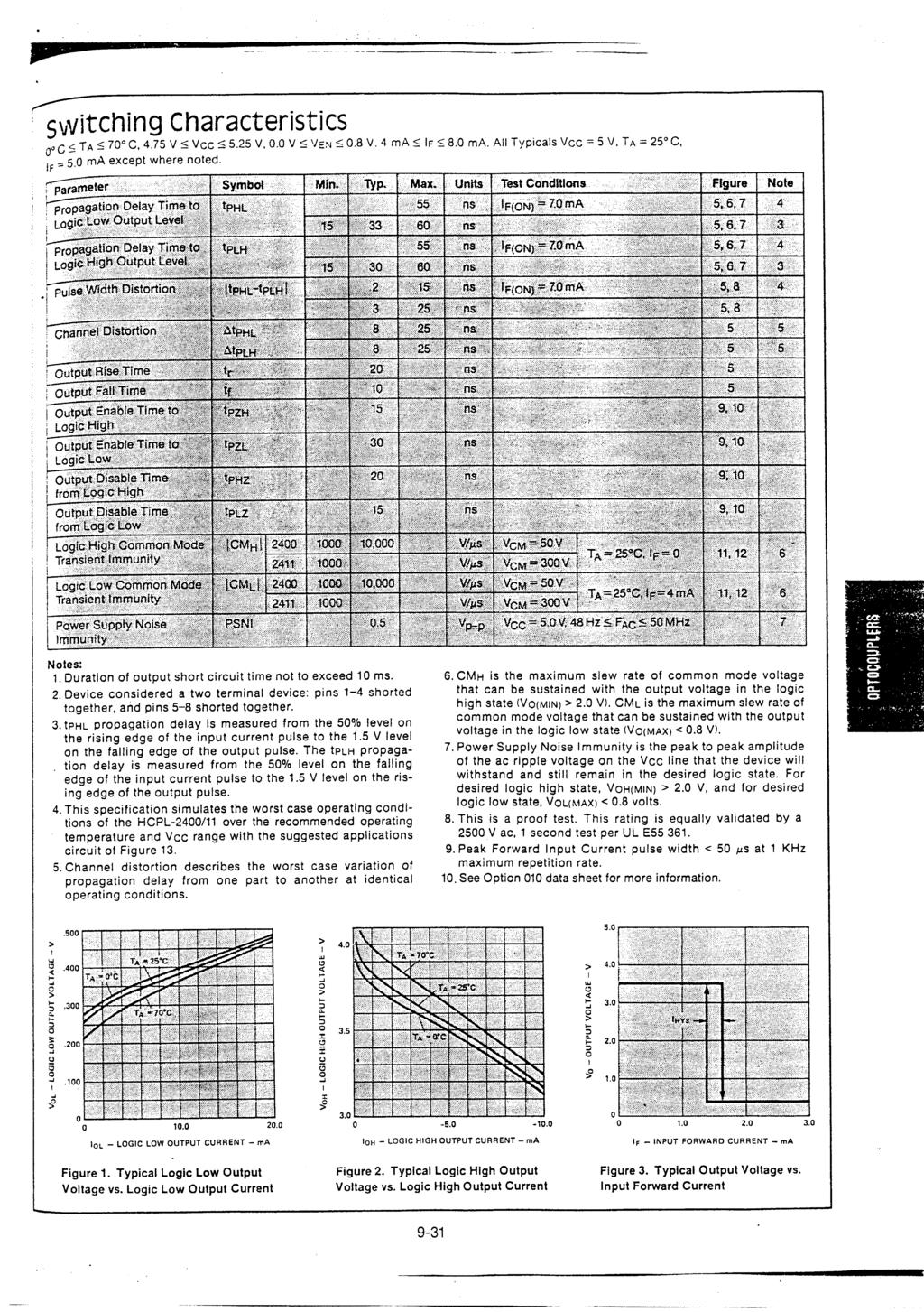
8 8 Switching Specifications 0 C T A 70 C, 4.75 V V CC 5.25 V, 4 ma I F(ON) 8 ma, 0 V V F(OFF) 0.8 V. All typicals at T A = 25 C, V CC = 5 V, I F(ON) = 6.0 ma, V F(OFF) = 0 V, except where noted. See Note 11. Device Parameter Symbol HCPL- Min. Typ.* Max. Units Test Conditions Figure Note Propagation Delay t PHL 55 ns I F(ON) = 7 ma 5, 6, 7 1, 4, Time to Logic Low 5, 6 Output Level Propagation Delay t PLH 55 ns I F(ON) = 7 ma 5, 6, 7 1, 4, Time to Logic High 5, 6 Output Level Pulse Width t PHL -t PLH 2 15 ns I F(ON) = 7 ma 5, 8 6 Distortion 5 25 Propagation Delay t PSK 35 ns Per Notes & Text 15, 16 7 Skew Output Rise Time t r 20 ns 5 Output Fall Time t f 10 ns 5 Output Enable Time t PZH ns 9, 10 to Logic High Output Enable Time t PZL ns 9, 10 to Logic Low Output Disable Time t PHZ ns 9, 10 from Logic High Output Disable Time t PLZ ns 9, 10 from Logic Low Logic High Common CM H ,000 V/µs V CM = 300 V, T A = 25 C, 11 9 Mode Transient I F = 0 ma Immunity Logic Low Common CM L ,000 V/µs V CM = 300 V, T A = 25 C, 11 9 Mode Transient I F = 4 ma Immunity Power Supply Noise PSNI 0.5 V p-p V CC = 5.0 V, 10 Immunity 48 Hz = F AC 50 MHz *All typical values at T A = 25 C and V CC = 5 V, unless otherwise noted.
9 9 Package Characteristics Parameter Sym. Device Min. Typ.* Max. Units Test Conditions Fig. Note Input-Output V ISO 3750 V rms RH 50%, 3, 13 Momentary t = 1 min., Withstand Voltage** T A = 25 C Input-Output R I-O Ω V I-O = 500 Vdc 3 Resistance Input-Output C I-O 0.6 pf f = 1 MHz Capacitance V I-O = 0 Vdc Input-Input I I-I µa RH 45% 8 Insulation Leakage t = 5 s, Current V I-I = 500 Vdc Resistance R I-I Ω V I-I = 500 Vdc 8 (Input-Input) Capacitance C I-I pf f = 1 MHz 8 (Input-Input) *All typical values are at T A = 25 C. **The Input-Output Momentary Withstand Voltage is a dielectric voltage rating that should not be interpreted as an input-output continuous voltage rating. For the continuous voltage rating refer to the VDE 0884 Insulation Related Characteristics Table (if applicable), your equipment level safety specification or Agilent Application Note 1074 entitled Optocoupler Input-Output Endurance Voltage, publication number E. Notes: 1. Each channel. 2. Duration of output short circuit time not to exceed 10 ms. 3. Device considered a two terminal device: pins 1, 2, 3, and 4 shorted together, and pins 5, 6, 7, and 8 shorted together. 4. t PHL propagation delay is measured from the 50% level on the rising edge of the input current pulse to the 1.5 V level on the falling edge of the output pulse. The t PLH propagation delay is measured from the 50% level on the falling edge of the input current pulse to the 1.5 V level on the rising edge of the output pulse. 5. The typical data shown is indicative of what can be expected using the application circuit in Figure This specification simulates the worst case operating conditions of the HCPL-2400 over the recommended operating temperature and V CC range with the suggested application circuit of Figure Propagation delay skew is discussed later in this data sheet. 8. Measured between pins 1 and 2 shorted together, and pins 3 and 4 shorted together. 9. Common mode transient immunity in a Logic High level is the maximum tolerable (positive) dv CM /dt of the common mode pulse, V CM, to assure that the output will remain in a Logic High state (i.e., V O > 2.0 V. Common mode transient immunity in a Logic Low level is the maximum tolerable (negative) dv CM /dt of the common mode pulse, V CM, to assure that the output will remain in a Logic Low state (i.e., V O < 0.8 V). 10. Power Supply Noise Immunity is the peak to peak amplitude of the ac ripple voltage on the V CC line that the device will withstand and still remain in the desired logic state. For desired logic high state, V OH(MIN ) > 2.0 V, and for desired logic low state, V OL(MAX) < 0.8 V. 11. Use of a 0.1 µf bypass capacitor connected between pins 8 and 5 adjacent to the device is required. 12. Peak Forward Input Current pulse width < 50 µs at 1 KHz maximum repetition rate. 13. In accordance with UL 1577, each optocoupler is proof tested by applying an insulation test voltage 4500 V rms for one second (leakage detection current limit, I I-O 5 µa). This test is performed before the 100% Production test shown in the IEC/EN/DIN EN Insulation Related Characteristics Table, if applicable.
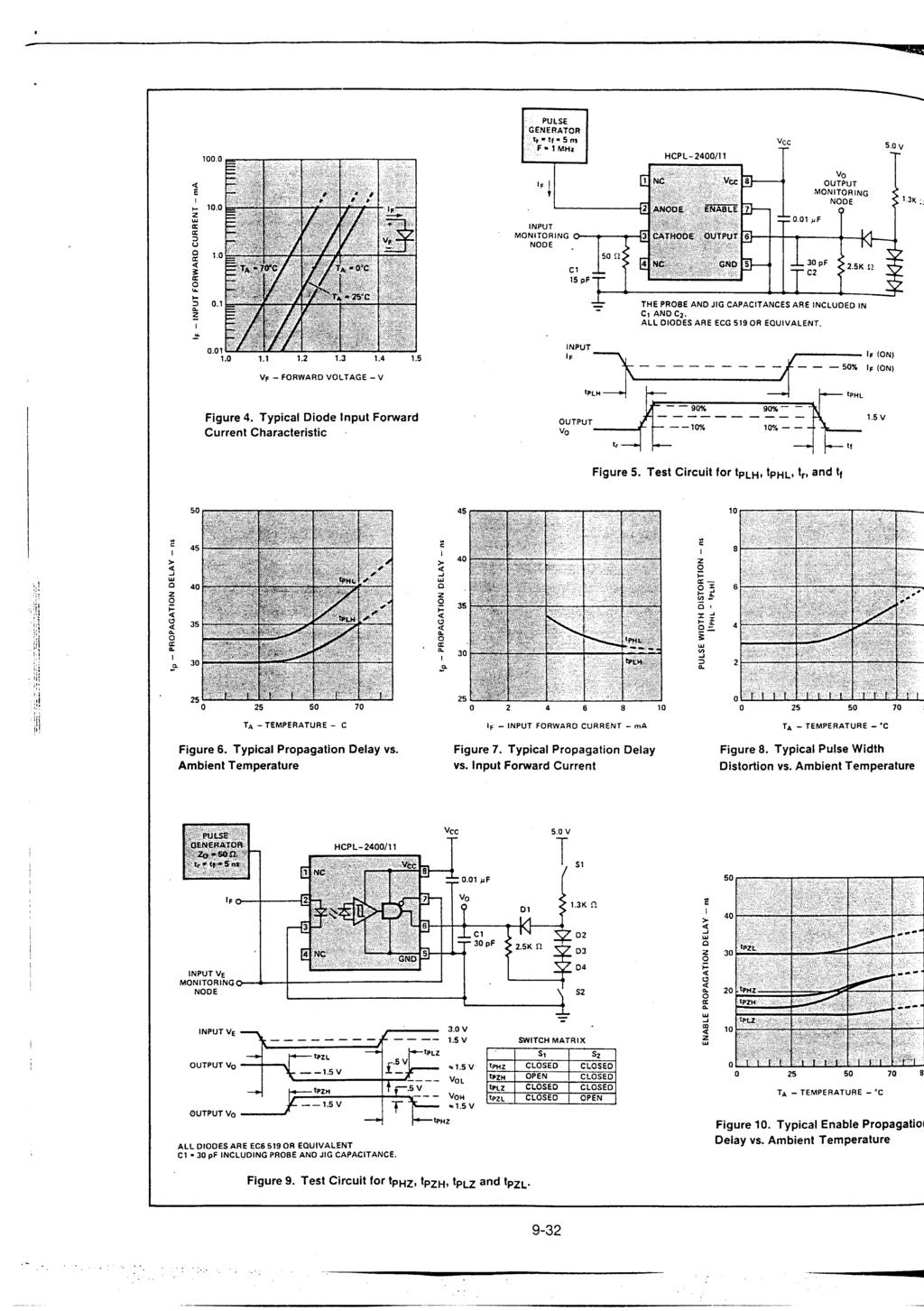
10 10 Figure 1. Typical Logic Low Output Voltage vs. Logic Low Output Current. Figure 2. Typical Logic High Output Voltage vs. Logic High Output Current. Figure 3. Typical Output Voltage vs. Input Forward Current. Figure 4. Typical Diode Input Forward Current Characteristic. Figure 5. Test Circuit for t PLH, t PHL, t r, and t f. Figure 6. Typical Propagation Delay vs. Ambient Temperature. Figure 7. Typical Propagation Delay vs. Input Forward Current. Figure 8. Typical Pulse Width Distortion vs. Ambient Temperature.
11 11 Figure 9. Test Circuit for t PHZ, t PZH, t PLZ and t PZL. Figure 10. Typical Enable Propagation Delay vs. Ambient Temperature. HCPL-2400/11 V CC V FF + I F B A NC V CC NC 5 GND V CM + PULSE GENERATOR 0.1 µf * OUTPUT VO MONITORING NODE C L = 15 pf OUTPUT POWER P S, INPUT CURRENT I S P S (mw) I S (ma) T S CASE TEMPERATURE C 200 Figure 11. Test Diagram for Common Mode Transient Immunity and Typical Waveforms. Figure 12. Thermal Derating Curve, Dependence of Safety Limiting Value with Case Temperature per IEC/EN/ DIN EN
12 12 Applications HCPL-2400 HCPL-2400 V Figure 13. Recommended 20 MBd HCPL-2400/30 Interface Circuit. Figure 14. Alternative HCPL-2400/30 Interface Circuit. DATA I F 50% INPUTS CLOCK V O 1.5 V I F V O 50% 1.5 V OUTPUTS DATA CLOCK t PSK t PSK t PSK Figure 15. Illustration of Propagation Delay Skew t PSK. Figure 16. Parallel Data Transmission Example. Figure 17. Modulation Code Selections. Figure 18. Typical HCPL-2400/30 Output Schematic.
13 13 Propagation Delay, Pulse- Width Distortion and Propagation Delay Skew Propagation delay is a figure of merit which describes how quickly a logic signal propagates through a system. The propagation delay from low to high (t PLH ) is the amount of time required for an input signal to propagate to the output, causing the output to change from low to high. Similarly, the propagation delay from high to low (t PHL ) is the amount of time required for the input signal to propagate to the output, causing the output to change from high to low (see Figure 5). Pulse-width distortion (PWD) results when t PLH and t PHL differ in value. PWD is defined as the difference between t PLH and t PHL and often determines the maximum data rate capability of a transmission system. PWD can be expressed in percent by dividing the PWD (in ns) by the minimum pulse width (in ns) being transmitted. Typically, PWD on the order of 20-30% of the minimum pulse width is tolerable; the exact figure depends on the particular application (RS232, RS422, T-1, etc.). Propagation delay skew, t PSK, is an important parameter to consider in parallel data applications where synchronization of signals on parallel data lines is a concern. If the parallel data is being sent through a group of optocouplers, differences in propagation delays will cause the data to arrive at the outputs of the optocouplers at different times. If this difference in propagation delays is large enough, it will determine the maximum rate at which parallel data can be sent through the optocouplers. Propagation delay skew is defined as the difference between the minimum and maximum propagation delays, either t PLH or t PHL, for any given group of optocouplers which are operating under the same conditions (i.e., the same drive current, supply voltage, output load, and operating temperature). As illustrated in Figure 15, if the inputs of a group of optocouplers are switched either ON or OFF at the same time, t PSK is the difference between the shortest propagation delay, either t PLH or t PHL, and the longest propagation delay, either t PLH or t PHL. As mentioned earlier, t PSK can determine the maximum parallel data transmission rate. Figure 16 is the timing diagram of a typical parallel data application with both the clock and the data lines being sent through optocouplers. The figure shows data and clock signals at the inputs and outputs of the optocouplers. To obtain the maximum data transmission rate, both edges of the clock signals are being used to clock the data; if only one edge were used, the clock signal would need to be twice as fast. Propagation delay skew represents the uncertainty of where an edge might be after being sent through an optocoupler. Figure 16 shows that there will be uncertainty in both the data and the clock lines. It is important that these two areas of uncertainty not overlap, otherwise the clock signal might arrive before all of the data outputs have settled, or some of the data outputs may start to change before the clock signal has arrived. From these considerations, the absolute minimum pulse width that can be sent through optocouplers in a parallel application is twice t PHZ. A cautious design should use a slightly longer pulse width to ensure that any additional uncertainty in the rest of the circuit does not cause a problem. The HCPL-2400/30 optocouplers offer the advantages of guaranteed specifications for propagation delays, pulse-width distortion, and propagation delay skew over the recommended temperature, input current, and power supply ranges. Application Circuit A recommended LED drive circuit is shown in Figure 13. This circuit utilizes several techniques to minimize the total pulse-width distortion at the output of the optocoupler. By using two inverting TTL gates connected in series, the inherent pulse-width distortion of each gate cancels the distortion of the other gate. For best results, the two seriesconnected gates should be from the same package. The circuit in Figure 13 also uses techniques known as prebias and peaking to enhance the performance of the optocoupler LED. Prebias is a small forward voltage applied to the LED when the LED is off. This small prebias voltage partially charges the junction capacitance of the LED, allowing the LED to turn on more quickly. The speed of the LED is further increased by applying
14 momentary current peaks to the LED during the turn-on and turnoff transitions of the drive current. These peak currents help to charge and discharge the capacitances of the LED more quickly, shortening the time required for the LED to turn on and off. Switching performance of the HCPL-2400/30 optocouplers is not sensitive to the TTL logic family used in the recommended drive circuit. The typical and worst-case switching parameters given in the data sheet can be met using common 74LS TTL inverting gates or buffers. Use of faster TTL families will slightly reduce the overall propagation delays from the input of the drive circuit to the output of the optocoupler, but will not necessarily result in lower pulse-width distortion or propagation delay skew. This reduction in overall propagation delay is due to shorter delays in the drive circuit, not to changes in the propagation delays of the optocoupler; optocoupler propagation delays are not affected by the speed of the logic used in the drive circuit. For product information and a complete list of distributors, please go to our web site. For technical assistance call: Americas/Canada: +1 (800) or (916) Europe: +49 (0) China: Hong Kong: (+65) India, Australia, New Zealand: (+65) Japan: (+81 3) (Domestic/International), or (Domestic Only) Korea: (+65) Singapore, Malaysia, Vietnam, Thailand, Philippines, Indonesia: (+65) Taiwan: (+65) Data subject to change. Copyright 2005 Agilent Technologies, Inc. Obsoletes EN February 28, EN

15
16
17
18
19
20
Agilent HCPL-0738 High Speed CMOS Optocoupler
 Agilent HCPL-078 High Speed CMOS Optocoupler Data Sheet Description The HCPL-078 is a dual-channel 1 MBd CMOS optocoupler in SOIC-8 package. The HCPL-078 optocoupler utilizes the latest CMOS IC technology
TRUTH TABLE (POSITIVE LOGIC) Z Z H L H H L L
 Z Z H L H H L L") HCPL-, HCPL-9 Low Input Current Logic Gate Optocouplers Data Sheet Description The HCPL-/9 are optically coupled logic gates that combine a GaAsP LED and an integrated high gain photo detector. The detector
HCPL-, HCPL-9 Low Input Current Logic Gate Optocouplers Data Sheet Description The HCPL-/9 are optically coupled logic gates that combine a GaAsP LED and an integrated high gain photo detector. The detector
Dual Channel Low Input Current, High Gain Optocouplers Technical Data
 Dual Channel Low Input Current, High Gain Optocouplers Technical Data HCPL-7 HCPL-7 HCPL-7 HCPL-7 Features High Current Transfer Ratio % Typical Low Input Current Requirements.5 ma Low Output Saturation
HCPL-270L/070L/273L/073L
 Low Input Current, High Gain, LVTTL/LVCMOS Compatible Optocouplers Description These high gain series couplers use a Light Emitting Diode and an integrated high gain photodetector to provide extremely
Dual Channel, High Speed Optocouplers Technical Data
 Dual Channel, High Speed Optocouplers Technical Data HCPL-5 HCPL-5 HCPL-454 HCPL-5 HCPL-5 HCPL-54 Features 5 kv/µs Minimum Common Mode Transient Immunity at V CM = 5 V (HCPL-454/54) High Speed: Mb/s TTL
MIL-STD-1772 Version Available (HCPL-52XX/62XX)
") H Very High CMR, Wide Logic Gate Optocouplers Technical Data HCPL- HCPL- HCPL- HCPL- HCNW HCPL- HCPL- HCPL- HCPL- HCNW Features kv/µs Minimum Common Mode Rejection (CMR) at V CM = V (HCPL-///, HCNW) Wide
H Very High CMR, Wide Logic Gate Optocouplers Technical Data HCPL- HCPL- HCPL- HCPL- HCNW HCPL- HCPL- HCPL- HCPL- HCNW Features kv/µs Minimum Common Mode Rejection (CMR) at V CM = V (HCPL-///, HCNW) Wide
Agilent Dual Channel, High Speed Optocouplers Data Sheet
 Agilent Dual Channel, High Speed Optocouplers Data Sheet HCPL-5, HCPL-5, HCPL-454 HCPL-5, HCPL-5, HCPL-54 Description These dual channel optocouplers contain a pair of light emitting diodes and integrated
 Distributed by: www.jameco.com --- The content and copyrights of the attached material are the property of its owner. HCPL-, HCPL-, HCPL-,HCPL-, HCPL-, HCPL-, HCPL-, HCPL-, HCNW, HCNW Very High CMR, Wide
Features. Applications
 ACPL-4 High CMR Intelligent Power Module and Gate Drive Interface Optocoupler Data Sheet Lead (Pb) Free RoHS fully compliant RoHS fully compliant options available; -xxxe denotes a lead-free product Description
Single Channel, High Speed Optocouplers Technical Data
 Single Channel, High Speed Optocouplers Technical Data N5/ HCNW5/ HCNW45/ HCPL-5 HCPL-45/ HCPL-5/ HCPL-45/ Features 5 kv/µs Minimum Common Mode Transient Immunity at V CM = 5 V (45/45) High Speed: Mb/s
HCPL-2201, HCPL-2202, HCPL-2211,HCPL-2212, HCPL-2231, HCPL-2232, HCPL-0201, HCPL-0211, HCNW2201, HCNW2211 Very High CMR, Wide V CC
 HCPL-, HCPL-, HCPL-,HCPL-, HCPL-, HCPL-, HCPL-, HCPL-, HCNW, HCNW Very High CMR, Wide Logic Gate Optocouplers Data Sheet Lead (Pb) Free RoHS fully compliant RoHS fully compliant options available; -xxxe
Schematic V F HCPL-7601/11 SHIELD. USE OF A 0.1 µf BYPASS CAPACITOR CONNECTED BETWEEN PINS 5 AND 8 IS REQUIRED (SEE NOTE 1).
.") CMOS/TTL Compatible, Low Input Current, High Speed, High CMR Optocoupler Technical Data HCPL-7601 HCPL-7611 Features Low Input Current Version of HCPL-2601/11 and 6N137 Wide Input Current Range: I F =
CMOS/TTL Compatible, Low Input Current, High Speed, High CMR Optocoupler Technical Data HCPL-7601 HCPL-7611 Features Low Input Current Version of HCPL-2601/11 and 6N137 Wide Input Current Range: I F =
 Distributed by: www.jameco.com ---44 The content and copyrights of the attached material are the property of its owner. HCPL-5, HCPL-5, HCPL-454 HCPL-5, HCPL-5, HCPL-54 Dual Channel, High Speed Optocouplers
High Speed CMOS Optocouplers. Technical Data HCPL-7100 HCPL Features. Description. Applications. Schematic
 H High Speed CMOS Optocouplers Technical Data HCPL-7100 HCPL-7101 Features 1 µm CMOS IC Technology Compatibility with All +5 V CMOS and TTL Logic Families No External Components Required for Logic Interface
Dual Channel, High Speed Optocouplers Technical Data
 Dual Channel, High Speed Optocouplers Technical Data HCPL-5 HCPL-5 HCPL-454 HCPL-5 HCPL-5 HCPL-54 Features 5 kv/µs Minimum Common Mode Transient Immunity at V CM = 5 V (HCPL-454/54) High Speed: Mb/s TTL
Features. Applications TRUTH TABLE (POSITIVE LOGIC) ON LOW
 ON LOW") HCPL-5 and HCPL-5 Dual Channel, High Speed Optocouplers Data Sheet Lead (Pb) Free RoHS fully compliant RoHS fully compliant options available; -xxxe denotes a lead-free product Description These dual channel
HCPL-5 and HCPL-5 Dual Channel, High Speed Optocouplers Data Sheet Lead (Pb) Free RoHS fully compliant RoHS fully compliant options available; -xxxe denotes a lead-free product Description These dual channel
Optically Coupled 20 ma Current Loop Receiver. Technical Data HCPL-4200
 H Optically Coupled 2 ma Loop Receiver Technical Data OPTOCOUPLERS HCPL-42 Features Data Output Compatible with LSTTL, TTL and CMOS 2 K Baud Data Rate at 14 Metres Line Length Guaranteed Performance over
HCPL-270L/070L/273L/073L Low Input Current, High Gain, LVTTL/LVCMOS Compatible Optocouplers. Features. Applications V O1 V O2 GND SHIELD
 HCPL-0L/00L/L/0L Low Input Current, High Gain, LVTTL/LVCMOS Compatible Optocouplers Data Sheet Description These high gain series couplers use a Light Emitting Diode and an integrated high gain photodetector
Features. Applications
 N5/, HCNW5/, HCNW45/ HCPL-5/45/45/5/5/45/45 Single Channel, High Speed Optocouplers Data Sheet Lead (Pb) Free RoHS fully compliant RoHS fully compliant options available; -xxxe denotes a lead-free product
AC/DC to Logic Interface Optocouplers Technical Data
 H AC/DC to Logic Interface Optocouplers Technical Data HCPL-37 HCPL-376 Features Standard (HCPL-37) and Low Input Current (HCPL-376) Versions AC or DC Input Programmable Sense Voltage Hysteresis Logic
Features. Applications ON LOW
 N9, N, HCPL-, HCPL-, HCNW9, HCNW- Low Input Current, High Gain Optocouplers Data Sheet Description These high gain series couplers use a Light Emitting Diode and an integrated high gain photodetector to
Features. Applications
 HCNW45/ HCPL-45/45/45/45 Single Channel, High Speed Optocouplers Data Sheet Lead (Pb) Free RoHS fully compliant RoHS fully compliant options available; -xxxe denotes a lead-free product Description These
 Distributed by: www.jameco.com --- The content and copyrights of the attached material are the property of its owner. N, HCNW, HCNW, HCNW, HCPL-, HCPL-, HCPL-, HCPL-, HCPL-, HCPL-, HCPL-, HCPL-, HCPL-,
Functional Diagram 6N137, HCPL-2601/2611 HCPL-0600/0601/0611 ANODE CATHODE TRUTH TABLE (POSITIVE LOGIC) OUTPUT H H OFF NC
 OUTPUT H H OFF NC") High CMR, High Speed TTL Compatible Optocouplers Technical Data N HCNW HCNW HCNW HCPL- HCPL- HCPL- HCPL- HCPL- HCPL- HCPL- HCPL- HCPL- HCPL- HCPL- Features kv/µs Minimum Common Mode Rejection (CMR) at
High CMR, High Speed TTL Compatible Optocouplers Technical Data N HCNW HCNW HCNW HCPL- HCPL- HCPL- HCPL- HCPL- HCPL- HCPL- HCPL- HCPL- HCPL- HCPL- Features kv/µs Minimum Common Mode Rejection (CMR) at
Features. Applications TRUTH TABLE (POSITIVE LOGIC) ON LOW
 ON LOW") HCPL-5, HCPL-5, HCPL-454 HCPL-5, HCPL-5, HCPL-54 Dual Channel, High Speed Optocouplers Data Sheet Lead (Pb) Free RoHS fully compliant RoHS fully compliant options available; -xxxe denotes a lead-free product
HCPL-5, HCPL-5, HCPL-454 HCPL-5, HCPL-5, HCPL-54 Dual Channel, High Speed Optocouplers Data Sheet Lead (Pb) Free RoHS fully compliant RoHS fully compliant options available; -xxxe denotes a lead-free product
Agilent HCPL-3100/HCPL-3101 Power MOSFET/IGBT Gate Drive Optocouplers
 Agilent HCPL/HCPL Power MOSFET/IGBT Gate Drive Optocouplers Data Sheet Description The HCPL/ consists of an LED* optically coupled to an integrated circuit with a power output stage. These optocouplers
High CMR Intelligent Power Module and Gate Drive Interface Optocoupler. Features. Specifications. Applications
 ACPL-P80 and ACPL-W80 High CMR Intelligent Power Module and Gate Drive Interface Optocoupler Data Sheet Lead (Pb) Free RoHS fully compliant RoHS fully compliant options available; -xxxe denotes a lead-free
Dual Channel, High Speed Optocouplers Technical Data
 Dual Channel, High Speed Optocouplers Technical Data HCPL-2530 HCPL-2531 HCPL-4534 HCPL-0530 HCPL-0531 HCPL-0534 Features 15 kv/µs Minimum Common Mode Transient Immunity at V CM = 1500 V (HCPL-4534/0534)
 Distributed by: www.jameco.com --- The content and copyrights of the attached material are the property of its owner. N, HCNW, HCNW, HCNW, HCPL-, HCPL-, HCPL-, HCPL-, HCPL-, HCPL-, HCPL-, HCPL-, HCPL-,
Features. Applications
 HCPL-42 Optically Coupled 2 ma Current Loop Receiver Data Sheet Lead (Pb) Free RoHS 6 fully compliant RoHS 6 fully compliant options available; -xxxe denotes a lead-free product Description The HCPL-42
ACPL-P480 and ACPL-W480
 High CMR Intelligent Power Module and Gate Drive Interface Optocoupler Description The high-speed ACPL-P48/W48 optocoupler contains a GaAsP LED, a photo detector, and a Schmitt trigger that eliminates
Features. Note: A 0.1 F bypass capacitor must be connected between pins Vcc and Ground. Specifications. Truth Table (Negative Logic)
") ACPL-M483/P483/W483 Inverted Logic High CMR Intelligent Power Module and Gate Drive Interface Optocoupler Data Sheet Description The ACPL-M483/P483/W483 fast speed optocoupler contains a AlGaAs LED and
ACPL-M483/P483/W483 Inverted Logic High CMR Intelligent Power Module and Gate Drive Interface Optocoupler Data Sheet Description The ACPL-M483/P483/W483 fast speed optocoupler contains a AlGaAs LED and
 Distributed by: www.jameco.com -8-8-22 The content and copyrights of the attached material are the property of its owner. HCPL-M, HCPL-M, HCPL-M Small Outline, Lead, High CMR, High Speed, Logic Gate Optocouplers
Features. Applications. Truth Table (Positive Logic) LED ENABLE OUTPUT
 LED ENABLE OUTPUT") ACNVE mm DTI, MBd Digital Optocoupler Data Sheet Description The new ACNVE is an optically coupled gate that combines a AlGaAs light emitting diode and an integrated photo detector housed in a widebody
ACNVE mm DTI, MBd Digital Optocoupler Data Sheet Description The new ACNVE is an optically coupled gate that combines a AlGaAs light emitting diode and an integrated photo detector housed in a widebody
ACPL-M61U-000E Wide Operating Temperature 10MBd Digital Optocoupler. Features. Applications
 ACPL-MU-E Wide Operating Temperature MBd Digital Optocoupler Data Sheet Lead (Pb) Free RoHS fully compliant RoHS fully compliant options available; -xxxe denotes a lead-free product Description This small
Features. Applications
 HCNW5/ HCPL-5/5/5/5 Single Channel, High Speed Optocouplers Data Sheet Lead (Pb) Free RoHS fully compliant RoHS fully compliant options available; -xxxe denotes a lead-free product Description These diode-transistor
Features. Applications
 N5/, HCNW5/ HCPL-5/5/5 Single Channel, High Speed Optocouplers Data Sheet Lead (Pb) Free RoHS fully compliant RoHS fully compliant options available; -xxxe denotes a lead-free product Description These
HCPL-0700, HCPL-0701, HCNW138, HCNW139, 6N139, 6N138, Low Input Current, High Gain Optocouplers. Features. Applications LOW HIGH
 HCPL-,, HCNW, HCNW9, N9, N, Low Input Current, High Gain Optocouplers Data Sheet Lead (Pb) Free RoHS fully compliant RoHS fully compliant options available; -xxxe denotes a lead-free product Description
ACNV2601. High Insulation Voltage 10-MBd Digital Optocoupler. Data Sheet. Description. Features. Applications
 High Insulation Voltage -MBd Digital Optocoupler Description The ACNV26 is an optically coupled gate that combines an AlGaAs light-emitting diode and an integrated photo detector housed in a widebody package.
20 ma Current Loop Transmitter/Receiver
 2 ma Current Loop Transmitter/Receiver Product Selection Device Part No. Package Data Rate kbd @ (meters) Prop Delay CMR-V/µs @ (Vcm) HCPL-41 1 8 V CC I+ 1 HCPL-42 8 V CC HCPL-41 HCPL-42 3 mil DIP 2 4
Functional Diagram ANODE CATHODE
 H High Bandwidth, Analog/Video Optocouplers Technical Data Features Wide Bandwidth [] : 7 MHz () 9 MHz () High Voltage Gain [] : 2. (). () Low G V Temperature Coefficient: -.%/ C Highly Linear at Low Drive
Data Sheet. HCPL-4562 HCNW4562 High Bandwidth, Analog/Video Optocouplers
 High Bandwidth, Analog/Video Optocouplers Data Sheet Description The and optocouplers provide wide bandwidth isolation for analog signals. They are ideal for video isolation when combined with their application
Functional Diagram HCPL-261A/261N HCPL-061A/061N V CC V E GND TRUTH TABLE (POSITIVE LOGIC) OUTPUT H H OFF NC
 OUTPUT H H OFF NC") H HCMOS Compatible, High CMR, MBd Optocouplers Technical Data HCPL-A HCPL-A HCPL-N HCPL-N HCPL-A HCPL-A HCPL-N HCPL-N Features HCMOS/LSTTL/TTL Performance Compatible V/µs Minimum Common Mode Rejection
H HCMOS Compatible, High CMR, MBd Optocouplers Technical Data HCPL-A HCPL-A HCPL-N HCPL-N HCPL-A HCPL-A HCPL-N HCPL-N Features HCMOS/LSTTL/TTL Performance Compatible V/µs Minimum Common Mode Rejection
ACPL-M50L, ACPL-054L, ACPL-W50L and ACPL-K54L Low Power, 1MBd Digital Optocoupler. Features. Applications GND
 ACPL-M5L, ACPL-5L, ACPL-W5L and ACPL-K5L Low Power, MBd Digital Optocoupler Data Sheet Lead (Pb) Free RoHS 6 fully compliant RoHS 6 fully compliant options available; -xxxe denotes a lead-free product
ACPL-M43T Automotive Wide Operating Temperature 1MBd Digital Optocoupler in a 5-Pin Surface Mount Plastic Package. Features. Applications.
 ACPL-M43T Automotive Wide Operating Temperature MBd Digital Optocoupler in a -Pin Surface Mount Plastic Package Data Sheet Lead (Pb) Free RoHS 6 fully compliant RoHS 6 fully compliant options available;
High CMR Line Receiver Optocouplers Technical Data
 High CMR Line Receiver Optocouplers Technical Data HCPL-2602 HCPL-2612 Features 1000 V/µs Minimum Common Mode Rejection (CMR) at V CM = 0 V for HCPL-2602 and. kv/µs Minimum CMR at V CM = 00 V for HCPL-2612
ACNT-H50L. 1-MBd Optocoupler in 15-mm Stretched SO8 Package. Data Sheet. Description. Features. Applications. Functional Diagram
 ACNT-H5L -MBd Optocoupler in 5-mm Stretched SO8 Package Description The ACNT-H5L is a single-channel -MBd optocoupler in Stretched SO8 footprint. It uses an insulating layer between the light emitting
HCPL-J456 HCNW4506. Functional Diagram. 20 kω 4 SHIELD
 Intelligent Power Module and Gate Drive Interface Optocouplers Technical Data HCPL- HCPL-J HCPL- HCNW Features Performance Specified for Common IPM Applications over Industrial Temperature Range: - C to
HCPL-M454 Ultra High CMR, Small Outline, 5 Lead, High Speed Optocoupler. Features
 HCPL-M44 Ultra High CMR, Small Outline, Lead, High Speed Optocoupler Data Sheet Lead (Pb) Free RoHS 6 fully compliant RoHS 6 fully compliant options available; -xxxe denotes a lead-free product Description
ACPL-071L and ACPL-074L Single-channel and Dual-channel High Speed 15 MBd CMOS optocoupler with Glitch-Free Power-Up Feature. Features.
 ACPL-7L and ACPL-7L Single-channel and Dual-channel High Speed MBd CMOS optocoupler with Glitch-Free Power-Up Feature Data Sheet Lead (Pb) Free RoHS fully compliant RoHS fully compliant options available;
HCPL-7723/ MBd 2 ns PWD High Speed CMOS Optocoupler. Features. Applications
 HCPL-7723/0723 50 MBd 2 ns PWD High Speed CMOS Optocoupler Data Sheet Lead (Pb) Free RoHS 6 fully compliant RoHS 6 fully compliant options available; -xxxe denotes a lead-free product Description Available
ACNV Amp Output Current IGBT Gate Drive Optocoupler in 500Mil DIP10 Package. Features. Applications
 ACNV0.5 Amp Output Current IGBT Gate Drive Optocoupler in 500Mil DIP0 Package Data Sheet Description The ACNV0 contains an AlGaAs LED, which is optically coupled to an integrated circuit with a power output
Very Low Power Consumption High Gain Optocouplers. Technical Data HCPL-4701 HCPL-4731 HCPL-070A HCPL-073A
 Very Low Power Consumption High Gain Optocouplers Technical Data HCPL-4701 HCPL-4731 HCPL-070A HCPL-073A Features Ultra Low Input Current Capability - 40 µa Specified for 3 V Operation Typical Power Consumption:
ACPL-K49T. Data Sheet
 Data Sheet ACPL-K9T Wide Operating Temperature Automotive R Coupler 0-kBd Digital Optocoupler Configurable as Low-Power, Low-Leakage Phototransistor Description The ACPL-K9T is a single-channel, hightemperature,
Functional Diagram HCPL-4701/070A
 Very Low Power Consumption High Gain Optocouplers Technical Data HCPL- HCPL- HCPL-A HCPL-A Features Ultra Low Input Current Capability - µa Specified for peration Typical Power Consumption: < mw Input
Features. Applications OFF
 HCPL Power Bipolar Transistor Base Drive Optocoupler Data Sheet Description The HCPL consists of a Silicondoped GaAs LED optically coupled to an integrated circuit with a power output stage. This optocoupler
Features. Specifications. Applications
 ACPL-77L and ACPL-07L.V/V High Speed CMOS Optocoupler Data Sheet Lead (Pb) Free RoHS fully compliant RoHS fully compliant options available; -xxxe denotes a lead-free product Description Available in either
Wide Operating Temperature Automotive Digital Optocoupler with R 2 Coupler Isolation and 5-Pin SMT Package. Features. Applications ANODE
 ACPL-MT Wide Operating Temperature Automotive Digital Optocoupler with R 2 Coupler Isolation and -Pin SMT Package Data Sheet Lead (Pb) Free RoHS 6 fully compliant RoHS 6 fully compliant options available;
Data Sheet. ASSR-1218, ASSR-1219 and ASSR-1228 Form A, Solid State Relay (Photo MOSFET) (60V/0.2A/10Ω) Features. Description. Functional Diagram
 (60V/0.2A/10Ω) Features. Description. Functional Diagram") ASSR-8, ASSR-9 and ASSR-8 Form A, Solid State Relay (Photo MOSFET) (0V/0.A/0Ω) Data Sheet Description The ASSR-XX Series consists of an AlGaAs infrared light-emitting diode (LED) input stage optically
ASSR-8, ASSR-9 and ASSR-8 Form A, Solid State Relay (Photo MOSFET) (0V/0.A/0Ω) Data Sheet Description The ASSR-XX Series consists of an AlGaAs infrared light-emitting diode (LED) input stage optically
Agilent HCPL-3140/HCPL Amp Output Current IGBT Gate Drive Optocoupler
 Agilent HCPL-/HCPL-. Amp Output Current IGBT Gate Drive Optocoupler Data Sheet Functional Diagram N/C ANODE CATHODE N/C SHIELD HCPL-/HCPL- V CC N.C. V O V EE Description The HCPL-/HCPL- family of devices
Data Sheet. Hermetically Sealed, Very High Speed, Logic Gate Optocouplers HCPL-540X,* , HCPL-543X, HCPL-643X,
 Hermetically Sealed, Very High Speed, Logic Gate Optocouplers Data Sheet HCPL-540X,* 596-89570, HCPL-543X, HCPL-643X, 596-8957 *See matrix for available extensions. Description These units are single and
ACPL-071L and ACPL-074L Single-channel and Dual-channel High Speed 15 MBd CMOS optocoupler with Glitch-Free Power-Up Feature.
 ACPL-071L and ACPL-07L Single-channel and Dual-channel High Speed 1 MBd CMOS optocoupler with Glitch-Free Power-Up Feature Data Sheet Lead (Pb) Free RoHS fully compliant RoHS fully compliant options available;
Data Sheet. ASSR-4118, ASSR-4119 and ASSR Form A, Solid State Relay (Photo MOSFET) (400V/0.10A/35 ) Features. Description. Functional Diagram
 (400V/0.10A/35 ) Features. Description. Functional Diagram") ASSR-, ASSR-9 and ASSR- Form A, Solid State Relay (Photo MOSFET) (00V/0.0A/ ) Data Sheet Description The ASSR-XX Series consists of an AlGaAs infrared light-emitting diode (LED) input stage optically coupled
ASSR-, ASSR-9 and ASSR- Form A, Solid State Relay (Photo MOSFET) (00V/0.0A/ ) Data Sheet Description The ASSR-XX Series consists of an AlGaAs infrared light-emitting diode (LED) input stage optically coupled
Features V O1 GND. Applications TRUTH TABLE (POSITIVE LOGIC) *5000 V rms
 *5000 V rms") N, HCNW, HCNW, HCNW, HCPL-, HCPL-, HCPL-, HCPL-, HCPL-, HCPL-, HCPL-, HCPL-, HCPL-, HCPL-, HCPL- High CMR, High Speed TTL Compatible Optocouplers Data Sheet Lead (Pb) Free RoHS fully compliant RoHS fully
N, HCNW, HCNW, HCNW, HCPL-, HCPL-, HCPL-, HCPL-, HCPL-, HCPL-, HCPL-, HCPL-, HCPL-, HCPL-, HCPL- High CMR, High Speed TTL Compatible Optocouplers Data Sheet Lead (Pb) Free RoHS fully compliant RoHS fully
Features. Applications
 ACPL-M62L Ultra Low Power MBd Digital Optocoupler Data Sheet Description The ACPL-M62L is an optically-coupled optocoupler that combines an AlGaAs light-emitting diode and an integrated high-gain photo
Low C x R, Form A, Solid State Relay (Photo MOSFET) (400V/100 /15pF) Features. Applications. Truth Table. Close
 (400V/100 /15pF) Features. Applications. Truth Table. Close") ASSR-0C and ASSR-0C Low C x R, Form A, Solid State Relay (Photo MOSFET) (00V/00 /pf) Data Sheet Lead (Pb) Free RoHS fully compliant RoHS fully compliant options available; -xxxe denotes a lead-free product
ASSR-0C and ASSR-0C Low C x R, Form A, Solid State Relay (Photo MOSFET) (00V/00 /pf) Data Sheet Lead (Pb) Free RoHS fully compliant RoHS fully compliant options available; -xxxe denotes a lead-free product
Telecommunication Switching Equipment Reed Relay Replacement 28 Vdc, 24 Vac, 48 Vdc Load Driver Industrial Relay Coil Driver
 60 V/0.7 Ohm, General Purpose, 1 Form A, Solid State Relay Technical Data HSSR-8060 Features Compact Solid-State Bidirectional Switch Normally-Off Single-Pole Relay Function (1 Form A) 60 V Output Withstand
Features. Applications
 HCPL-9000/-0900, -900/-090, HCPL-90/-09, -900J/-090J, HCPL-90J/-09J, -90J/-09J High Speed Digital Isolators Data Sheet Lead (Pb) Free RoHS 6 fully compliant RoHS 6 fully compliant options available; -xxxe
HCPL-4701/-4731/-070A/-073A Very Low Power Consumption High Gain Optocouplers HCPL-4731/073A
 HCPL-/-/-A/-A Very Low Power Consumption High Gain Optocouplers Data Sheet Features Ultra low input current capability - µa Specified for V operation Typical power consumption: < mw Input power: < µw Output
8 PIN DIP HIGH SPEED LOW INPUT CURRENT LOGIC GATE PHOTOCOUPLER EL220X SERIES
 Features 1kV/μs min. common mode transient immunity Guaranteed performance from -40 to 85 Wide V CC range (4.5V to 20V) 5Mbd typical signal rate Low input current (1.6mA) High isolation voltage between
HCPL-7723/ MBd 2 ns PWD High Speed CMOS Optocoupler. Features. Applications
 HCPL-77/07 50 MBd ns PWD High Speed CMOS Optocoupler Data Sheet Lead (Pb) Free RoHS 6 fully compliant RoHS 6 fully compliant options available; -xxxe denotes a lead-free product Description Available in
HCPL-4506/J456/0466, HCNW4506 Intelligent Power Module and Gate Drive Interface Optocouplers. Features. Applications
 HCPL-/J/, HCNW Intelligent Power Module and Gate Drive Interface Optocouplers Data Sheet Lead (Pb) Free RoHS fully compliant RoHS fully compliant options available; -xxxe denotes a lead-free product Description
ASSR-3210, ASSR-3211, ASSR-3220 General Purpose, Form A, Solid State Relay (Photo MOSFET) (250V/0.2A/10Ω) Features
 (250V/0.2A/10Ω) Features") ASSR-0, ASSR-, ASSR-0 General Purpose, Form A, Solid State Relay (Photo MOSFET) (0V/0.A/0Ω) Data Sheet Lead (Pb) Free RoHS fully compliant RoHS fully compliant options available; -xxxe denotes a lead-free
ASSR-0, ASSR-, ASSR-0 General Purpose, Form A, Solid State Relay (Photo MOSFET) (0V/0.A/0Ω) Data Sheet Lead (Pb) Free RoHS fully compliant RoHS fully compliant options available; -xxxe denotes a lead-free
ACNV4506 Intelligent Power Module and Gate Drive Interface Optocouplers. Features. Specifications. Applications
 ACNV0 Intelligent Power Module and Gate Drive Interface Optocouplers Data Sheet Description The ACNV0 device contains a GaAsP LED optically coupled to an integrated high gain photo detector. Minimized
CSA Approved VDE0884 Approved -V IORM = 560 Vpeak for HCPL-0466 Option 060 -V IORM = 630 Vpeak for HCPL-4506 Option 060 -V IORM = 891 Vpeak for
 Intelligent Power Module and Gate Drive Interface Optocouplers Technical Data HCPL- HCPL-J HCPL- HCNW Features Performance Specified for Common IPM Applications over Industrial Temperature Range: - C to
HCPL-520x, HCPL-523x, HCPL-623x, HCPL-625x, and Hermetically Sealed Low IF, Wide VCC, Logic Gate Optocouplers.
 HCPL-520x, HCPL-523x, HCPL-623x, HCPL-625x, 5962-88768 and 5962-88769 Hermetically Sealed Low IF, Wide VCC, Logic Gate Optocouplers Data Sheet Description These units are single, dual and quad channel,
Features L H. Applications
 ACPL-MU-000E Wide Operating Temperature Intelligent Power Module Optocoupler Small Outline, Leads Data Sheet Lead (Pb) Free RoHS fully compliant RoHS fully compliant options available; -xxxe denotes a
HIGH SPEED-10 MBit/s LOGIC GATE OPTOCOUPLERS
 HIGH SPEED- MBit/s DESCRIPTION The, /6 single-channel and /6 dual-channel optocouplers consist of a 5 nm AlGaAS LED, optically coupled to a very high speed integrated photodetector logic gate with a strobable
HCPL-7800 Isolation Amplifier
 Products > Optocouplers - Plastic > Plastic Miniature Isolation Amplifier > HCPL-7800 HCPL-7800 Isolation Amplifier Description The HCPL-7800 isolation amplifier family was designed for current sensing
LTV-063L LVTTL/LVCMOS Compatible 3.3V Dual-Channel Optocouplers (10 Mb/s)
") LTV-063L LVTTL/LVCMOS Compatible 3.3V Dual-Channel Optocouplers (10 Mb/s) Description The LTV-063L consists of a high efficient AlGaAs Light Emitting Diode and a high speed optical detector. This design
LTV-063L LVTTL/LVCMOS Compatible 3.3V Dual-Channel Optocouplers (10 Mb/s) Description The LTV-063L consists of a high efficient AlGaAs Light Emitting Diode and a high speed optical detector. This design
HCPL Amp Output Current, High Speed, Gate Drive Optocoupler
 HCPL-. Amp Output Current, High Speed, Gate Drive Optocoupler Data Sheet Lead (Pb) Free RoHS fully compliant RoHS fully compliant options available; -xxxe denotes a lead-free product Description This family
Positive Logic High CMR Intelligent Power Module and Gate Drive Interface Photocoupler
 PHOTOCOUPLER Positive Logic High CMR Intelligent Power Module and Gate Drive Interface Photocoupler Description The fast speed photocoupler contains a AlGaAs LED and photo detector with built-in Schmitt
HCPL-7840 Isolation Amplifier
 Products > Optocouplers - Plastic > Plastic Miniature Isolation Amplifier > HCPL-7840 HCPL-7840 Isolation Amplifier Description The HCPL-7840 isolation amplifier family was designed for current sensing
Agilent HCPL-354 AC Input Phototransistor Optocoupler SMD Mini-Flat Type
 Agilent HCPL-34 AC Input Phototransistor Optocoupler SMD Mini-Flat Type Data Sheet Description The HCPL-34 contains a phototransistor, optically coupled to two light emitting diodes connected inverse parallel.
LTV-M601 High Speed 10MBit/s TTL Compatible Optocouplers
 LTV-M61 High Speed 1MBit/s TTL Compatible Optocouplers Description The LTV-M61 consists of a high efficient AlGaAs Light Emitting Diode and a high speed optical detector. This design provides excellent
ASSR-1510, ASSR-1511, ASSR-1520, ASSR-1530
 Data Sheet ASSR-, ASSR-, ASSR-, ASSR- (Photo MOSFET) (V/.A/.Ω) Description The ASSR-XX Series is specifically designed for high current applications, commonly found in the industrial applications. The
Features. Applications
 Data Sheet ACSL-0 Dual-Channel (Bidirectional) -MBd CMOS Buffered Input Digital Optocoupler Description The ACSL-0 is a dual-channel bidirectional -MBd digital optocoupler that uses CMOS IC technology
HCPL-9000/-0900, -9030/-0930, HCPL-9031/-0931, -900J/-090J, HCPL-901J/-091J, -902J/-092J
 Data Sheet HCPL-9000/-0900, -9030/-0930, HCPL-901J/-091J, -902J/-092J Description The HCPL-90xx and HCPL-09xx CMOS digital isolators feature high speed performance and excellent transient immunity specifications.
Features. Truth Table. Applications L H
 ACPL-MT Automotive Intelligent Power Module with R 2 Coupler Isolation and Small Outline, Lead Package Data Sheet Lead (Pb) Free RoHS fully compliant RoHS fully compliant options available; -xxxe denotes
Industrial Inverters Switch Mode Power Supplies (SMPS)
") H. Amp Output Current IGBT Gate Drive Optocoupler Technical Data HCPL- Features. A Minimum Peak Output Current kv/µs Minimum Common Mode Rejection (CMR) at V CM = V. V Maximum Low Level Output Voltage
H. Amp Output Current IGBT Gate Drive Optocoupler Technical Data HCPL- Features. A Minimum Peak Output Current kv/µs Minimum Common Mode Rejection (CMR) at V CM = V. V Maximum Low Level Output Voltage
HCPL-520x, HCPL-523x, HCPL-623x, HCPL-625x, and
 HCPL-520x, HCPL-523x, HCPL-623x, HCPL-625x, 5962-88768 and 5962-88769 1 Hermetically Sealed Low IF, Wide VCC, Logic Gate Optocouplers Description These units are single, dual and quad channel, hermetically
HCPL-260L/060L/263L/063L High Speed LVTTL Compatible 3.3 Volt Optocouplers. Features. Applications V O1 GND
 HCPL-L/L/L/L High Speed LVTTL Compatible. Volt Optocouplers Data Sheet Lead (Pb) Free RoHS fully compliant RoHS fully compliant options available; -xxxe denotes a lead-free product Description The HCPL-L/L/L/L
ACPL-P314 and ACPL-W Amp Output Current IGBT Gate Driver Optocoupler. Features. Specifications
 ACPL-P and ACPL-W 0. Amp Output Current IGBT Gate Driver Optocoupler Data Sheet Lead (Pb) Free RoHS fully compliant RoHS fully compliant options available; -xxxe denotes a lead-free product Description
HCPL-261A, HCPL-061A, HCPL-263A, HCPL-063A HCPL-261N, HCPL-061N, HCPL-263N, HCPL-063N HCMOS Compatible, High CMR, 10 MBd Optocouplers.
 HCPL-A, HCPL-A, HCPL-A, HCPL-A HCPL-N, HCPL-N, HCPL-N, HCPL-N HCMOS Compatible, High CMR, MBd Optocouplers Data Sheet Lead (Pb) Free RoHS fully compliant RoHS fully compliant options available; -xxxe denotes
ACPL-M75L Single-channel High Speed 15 MBd CMOS optocoupler with Glitch-Free Power-Up Feature. Features. Applications
 ACPL-M7L Single-channel High Speed MBd CMOS optocoupler with Glitch-Free Power-Up Feature Data Sheet Lead (Pb) Free RoHS 6 fully compliant RoHS 6 fully compliant options available; -xxxe denotes a lead-free
ACNW Amp High Output Current IGBT Gate Drive Optocoupler. Features. Applications
 ACNW9. Amp High Output Current IGBT Gate Drive Optocoupler Data Sheet Lead (Pb) Free RoHS fully compliant RoHS fully compliant options available; -xxxe denotes a lead-free product Description The ACNW9
HIGH SPEED-10 MBit/s LOGIC GATE OPTOCOUPLERS
 DESCRIPTION The, /6 single-channel and /6 dual-channel optocouplers consist of a 5 nm AlGaAS LED, optically coupled to a very high speed integrated photodetector logic gate with a strobable output. This
ACPL-W70L-000E and ACPL-K73L-000E Single-channel and Dual-channel High Speed 15 MBd CMOS optocoupler with Glitch-Free Power-Up Feature.
 ACPL-W7L-E and ACPL-K7L-E Single-channel and Dual-channel High Speed MBd CMOS optocoupler with Glitch-Free Power-Up Feature Data Sheet Lead (Pb) Free RoHS fully compliant RoHS fully compliant options available;
1/12. Photocoupler LTV-M456 series. Intelligent Power Module and Gate Drive Interface Optocoupler 1. DESCRIPTION. 1.1 Features. Functional Diagram
 Photocoupler Intelligent Power Module and Gate Drive Interface Optocoupler 1. DESCRIPTION The contain a AlGaAs LED optically coupled to an integrated high gain photo detector. Minimized propagation delay
ACSL-6xx0 Multi-Channel and Bi-Directional, 15 MBd Digital Logic Gate Optocoupler
 ACSL-xx Multi-Channel and Bi-Directional, MBd Digital Logic Gate Optocoupler Data Sheet Description ACSL-xx are truly isolated, multi-channel and bi-directional, high-speed optocouplers. Integration of