sub-mm-wave ICs, University of California, Santa Barbara
|
|
|
- Phyllis Perkins
- 6 years ago
- Views:
Transcription
1 20th Annual Workshop on Interconnections within High Speed Digital Systems, Santa Fe, New Mexico, 3 6 May 2009 THz Transistors, sub-mm-wave ICs, mm-wave Systems Mark Rodwell University of California, Santa Barbara rodwell@ece.ucsb.edu , fax
2 The End (of Moore's Law) is Near (?) It's a great time to be working on electronics! Things to work on: InP transistors: extend to 3-4 THz GHz & low-thz ICs GaN HEMTs: powerful transmitters from GHz Si MOSFETs: scale them past 16 nm III-V MOSFETs: help keep VLSI scaling (maybe) VLSI transistors: subvert Boltzmann solve power crisis mm-wave VLSI: massively complex ICs to re-invent radio Our focus today: THz transistors - how and why
3 Why THz Transistors?


4 Why Build THz Transistors? 500 GHz digital logic fiber optics THz amplifiers THz radios imaging, sensing, communications precision analog design at microwave frequencies high-performance receivers Higher-Resolution Microwave ADCs, DACs, DDSs

5 What Would You Do With a THz Transistor? 640 Gb/s ETDM optical fiber links GHz imaging systems mm-wave mm wave communication links


6 At High Frequencies The Atmosphere Is Opaque Mark Rosker IEEE IMS 2007

7 What Else Would You Do With a THz Transistor? precision, high-performance analog microwave circuits higher resolution microwave higher-resolution microwave ADCs, DACs, DDSs
8 How to Make THz Transistors


9 Simple Device Physics: Resistance bulk resistance contact t resistance contact t resistance -perpendicular - parallel bulk T R ρ ρ R A A contact R ρcontact + ρ A sheet W ' 3L Good approximation for contact widths less than 2 transfer lengths.


10 Simple Device Physics: Depletion Layers capacitance transit time space-charge limited current C ε A T T I 2εv τ max ( V + 2φ ) 2 2v + applied Vdepletion A T I C Δ V ΔT where C I τ max V applied + V depletion + 2φ


11 Simple Device Physics: Thermal Resistance Exact Carslaw & Jaeger 1959 Long, Narrow Stripe HBT Emitter, FET Gate R th 1 πk th L ln L W + 1 πk th L cylindrical heat flow near junction spherical heat flow far from junction R th + 1 πk th 1 πk th W sinh L 1 sinh 1 L W W L Square ( L by L ) IC on heat sink R th 1 4K th L 1 + πk th L planar heat flow spherical heat flow near surface far from surface


12 Simple Device Physics: Fringing Capacitance C L W ε εε T parallel - plate fringing C L slowly - varying function ε of W1 / G and W2 / G (1 to 3) ε wiring capacitance FET parasitic capacitances C / L > ε C parasitic / L ~ ε VLSI power-delay limits FET scaling constraints


13 Frequency Limits and Scaling Laws of (most) Electron Devices τ thickness C area / thickness R / area R I PIN photodiode top ρ bottom contact Δ T bottom ρ area contact max, space-charge-limit power length + ρ 4 sheet area / width length length egt log width ( thickness) 2 R Rtop To double bandwidth, reduce thicknesses 2:1 Improve contacts 4:1 reduce width 4:1, keep constant length increase current density 4:1
14 Bipolar Transistor Scaling Laws W e T b W bc T c Changes required to double transistor bandwidth: ( ) emitter length L E parameter change collector depletion layer thickness decrease 2:1 base thickness decrease 1.414:1 emitter junction width decrease 4:1 collector junction width decrease 4:1 emitter contact resistance decrease 4:1 current density increase 4:1 base contact resistivity decrease 4:1 Linewidths scale as the inverse square of bandwidth because thermal constraints dominate.

 increase 2:1 Linewidths scale as the inverse of bandwidth because fringing capacitance does")
15 FET Scaling Laws LG Changes required to double transistor bandwidth: ( ) gate width W G parameter change gate length decrease 2:1 gate dielectric capacitance density increase 2:1 gate dielectric equivalent thickness decrease 2:1 channel electron density increase 2:1 source & drain contact resistance decrease 4:1 current density (ma/μm) increase 2:1 Linewidths scale as the inverse of bandwidth because fringing capacitance does not scale.
16 Thermal Resistance Scaling : Transistor, Substrate, Package cylindricall heat flow near junction spherical flow for r > L e planar flow for r > D HBT / 2 P L e P P Tsub D / 2 ΔTsubstrate ln 2 π K InPLE We πk InP LE D K InP D increases logarithmically insignificant variation increases quadratically if T sub is constant ΔT package π K P Cu chip W chip junctio on temperature ris se, Kelvin 140 Tsub 40 μm (150 GHz / f clock ) HBT CML IC total substrate: cylindrical+spherical regions package 20 substrate: planar region master-slave D-Flip-Flop clock frequency, GHz Wiring lenghts scale as 1/bandwidth. Power density, scales as (bandwidth) 2.

17 Thermal Resistance Scaling : Transistor, Substrate, Package cylindricall heat flow near junction spherical flow for r > L e planar flow for r > D HBT / 2 P L e P P Tsub D / 2 ΔTsubstrate ln 2 π K InPLE We πk InP LE D K InP D increases logarithmically insignificant variation increases quadratically if T sub is constant ΔT package π K P Cu chip W chip junctio on temperature ris se, Kelvin 140 T sub 40 μm (150 GHz / f clock ) 120 total HBT CML IC 100 Probable best solution: 80 substrate: cylindrical+spherical regions package 20 substrate: planar region Wiring lenghts scale as Thermal Vias ~500 nm below InP subcollector 1/bandwidth. Power density,...over full active IC area. master-slave D-Flip-Flop clock frequency, GHz scales as (bandwidth) 2.
18 Electron Plasma Resonance: Not a Dominant Limit T 1 L kinetic 2 * A q nm T 1 Rbulk 2 * A q nm τ m C displacement εa T dielectric relaxation frequency f f dielecic C 1 σ 2π ε 1/ 2π displacement R bulk scattering frequency f dielecicl i 1 R π L 1 2πτ m bulk 2 kinetic plasma frequency f plasma 1/ 2π L C kinetic displacement n - InGaAs / cm p - InGaAs / cm THz 7 THz 74 THz 80 THz 12 THz 31THz
19 Electron Plasma Resonance: Not a Dominant Limit T 1 L kinetic 2 * A q nm T 1 Rbulk 2 * A q nm τ m C displacement εa T dielectric relaxation frequency f dielecic C 1 σ 2π ε 1/ 2π displacement R bulk scattering frequency f dielecic i 1 R π L 1 2πτ m bulk 2 kinetic plasma frequency f plasma 1/ 2π L C kinetic displacement n - InGaAs / cm p - InGaAs / cm THz 7 THz 74 THz 80 THz 12 THz 31THz
20 Electron Plasma Resonance: Not a Dominant Limit T 1 L kinetic 2 * A q nm T 1 Rbulk 2 * A q nm τ m C displacement εa T dielectric relaxation frequency f dielecic C 1 σ 2π ε 1/ 2π displacement R bulk scattering frequency f dielecic i 1 R π L 1 2πτ m bulk 2 kinetic plasma frequency f plasma 1/ 2π L C kinetic displacement n - InGaAs / cm p - InGaAs / cm THz 7 THz 74 THz 80 THz 12 THz 31THz


21 Electron Plasma Resonance: Not a Dominant Limit T 1 L kinetic 2 * A q nm T 1 Rbulk 2 * A q nm τ m C displacement εa T dielectric relaxation frequency f dielecic C 1 σ 2π ε 1/ 2π displacement R bulk scattering frequency f scattering 1 2πτ 1 R π L m bulk 2 kinetic plasma frequency f plasma 1/ 2π L C kinetic displacement n - InGaAs / cm p - InGaAs / cm THz 7 THz 74 THz 80 THz 12 THz 31THz


: very")

22 THz & nm Transistors: it's all about the interfaces Metal-semiconductor interfaces (Ohmic contacts): very low resistivity Dielectric-semiconductor interfaces (Gate dielectrics): very high capacitance density Transistor & IC thermal resistivity.
23 THz Bipolar Transistors
24 InP Bipolar Transistor Scaling Roadmap industry university university appears maybe industry feasible emitter nm width Ω μm 2 access ρ base nm contact width, Ω μm 2 contact ρ collector nm thick, ma/μm 2 current density V, breakdown f τ GHz W e f max GHz T b power amplifiers GHz digital 2:1 divider GHz W bc T c
25 InP DHBTs: September GHz 500 GHz 600 GHz 700 GHz 800 GHz 900 GHz f max f τ Teledyne DBHT popular f ( f τ τ or f + f max max metrics ti : alone ) / 2 f (GH Hz) max Updated Sept f t (GHz) UIUC DHBT NTT DBHT ETHZ DHBT UIUC SHBT UCSB DHBT NGST DHBT HRL DHBT IBM SiGe Vitesse DHBT (1 f τ f τ f max + 1 f max ) 1 much better metrics : power amplifiers: PAE, associated gain, mw/ μm low noise amplifiers: F min digital : f ( C ( R ( R ( τ clock b cb ex, associated gain, I, hence ΔV / I c c ), / ΔV ), Ic / Δ V ), + τ ) bb c
 Z. Griffith M. Urteaga P. Rowell D. Pierson B. Brar V.")
26 512 nm InP DHBT Laboratory Technology 500 nm mesa HBT 150 GHz M/S latches 175 GHz amplifiers UCSB / Teledyne / GCS UCSB 500 nm sidewall HBT DDS IC: 4500 HBTs GHz op-amps Production ( Teledyne ) Z. Griffith M. Urteaga P. Rowell D. Pierson B. Brar V. Paidi Teledyne f τ 405 GHz f max 392 GHz V br, ceo 4 V Teledyne / BAE 20 GHz clock Teledyne / UCSB dbm 2 GHz with 1 W dissipation


27 150 nm thick collector 256 nm Generation 40 InP DHBT GHz Amplifier 200 GHz master-slave latch design Z. Griffith, E. Lind J. Hacker, M. Jones db H 21 f τ 424 GHz U f max 780 GHz nm thick collector Hz 30 db U f τ 560 GHz H 21 f max 560 GHz Hz 60 nm thick collector db U H 21 Hz m 2 ma/μ ma/μm 2 ma/μm V ce V ce 10 f 218 GHz 10 max f 660 GHz t V ce


 Gain (db)")

28 324 GHz Medium Power Amplifiers in 256 nm HBT ICs designed by Jon Hacker / Teledyne Teledyne 256 nm process flow- Hacker et al, 2008 IEEE MTT-S ~2 mw saturated output power Ga ain (db), Pow wer (dbm), PAE (%) Output Power (dbm) Gain (db) Drain Current (ma) PAE (%) Cur rrent, ma Input Power (dbm) 0
29 InP Bipolar Transistor Scaling Roadmap industry university university appears maybe industry feasible emitter nm width Ω μm 2 access ρ base nm contact width, Ω μm 2 contact ρ collector nm thick, ma/μm 2 current density V, breakdown f τ GHz W e f max GHz T b power amplifiers GHz digital 2:1 divider GHz W bc T c
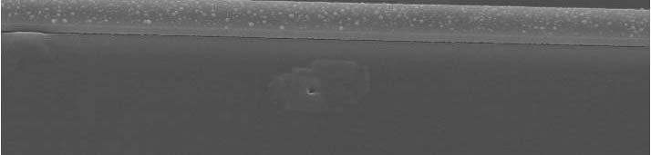
30 Conventional ex-situ contacts are a mess THz transistor bandwidths: very low-resistivity contacts are required textbook contact with surface oxide with metal penetration Interface barrier resistance Further intermixing during high-current operation degradation
31 Ohmic Contacts Good Enough for 3 THz Transistors 64 nm (2.0 THz) HBT needs ~ 2 Ω - μm 2 contact t resistivities iti 32 nm (2.8 THz) HBT needs ~ 1 Ω - μm 2 Contacts to N-InGaAs*: Mo MBE in-situ 2.22 (+/- 0.5) Ω - μm 2 TiW ex-situ ~2.2 Ω - μm 2 Contacts to P-InGaAs: Mo MBE in-situ below 2.5 Ω - μm 2 Pd/... ex-situ ~1 (+/-?) Ω - μm 2 *measured emitter resistance remains higher than that of contacts.


32 Process Must Change Greatly for 128 / 64 / 32 nm Nodes control undercut thinner emitter thinner emitter thinner base metal thinner base metal excess base metal resistance Undercutting of emitter ends {101}A planes: fast {111}A planes: slow


33 128 / 64 nm process: where we are going Developing scalable self-aligned base process 0.3 Ω-μm 2 resistivity emitter contacts - in-situ, in MBE 2 Ω-μm 2 resistivity base contacts - in-situ, in MBE target ~2000 GHz device
34 THz Field-Effect Transistors (THz HEMTs)
35 FET Scaling Laws LG Changes required to double transistor bandwidth: ( ) gate width W G parameter change gate length decrease 2:1 gate dielectric capacitance density increase 2:1 gate dielectric equivalent thickness decrease 2:1 channel electron density increase 2:1 source & drain contact resistance decrease 4:1 current density (ma/μm) increase 2:1 InGaAs HEMTs are best for mm-wave low-noise receivers......but there are difficulties in improving them further.


36 Why HEMTs are Hard to Improve 1 st challenge with HEMTs: reducing access resistance low electron density under gate recess limits current gate barrier lies under S/D contacts resistance gate barrier channel Source Gate Drain K Shinohara 2 nd challenge with HEMTs: low gate barrier high tunneling currents with thin barrier high emission currents with high electron density E F E well-γ E c III-V MOSFETs do not face these scaling challenges


37 III-V MOSFETs for VLSI Also Helps HEMT Development What is it? MOSFET with an InGaAs channel Why do it? low electron effective mass higher electron velocity more current, less charge at a given insulator thickness & gate length very low access resistance What are the problems? low electron effective mass constraints on scaling! must grow high-k on InGaAs, must grow InGaAs on Si


38 III-V MOSFETs in Development Wistey Singisetti Burek Lee. Rodwell Gossard top of gate side of gate Mo S/D metal with N+ InAs underneath gate Mo S/D metal with N+ InAs underneath InAs regrowth
39 III-V MOSFETs as a Scaling Path for THz HEMTs source contact metal gate sidewall gate dielectric drain contact N+ source N+ drain quantum well / channel barrier substrate Why? Much lower access resistance in S/D regions Higher gate barrier higher feasible electron density in channel Higher gate barrier gate dielectric can be made thinner Estimated Performance (?) Estimated Performance (?) 2 THz cutoff frequencies at 32 nm gate length
40 Applications of THz III-V Transistors

41 What Else Would You Do With a THz Transistor? precision, high-performance analog microwave circuits higher resolution microwave higher-resolution microwave ADCs, DACs, DDSs


42 mm-wave Op-Amps for Linear Microwave Amplification Reduce distortion with strong negative feedback DARPA / UCSB / Teledyne FLARE: Griffith & Urteaga linear response output powe er, dbm increasing feedback 2-tone intermodulation 300 GHz / 4 V InP HBT R. Eden input power, dbm measured GHz bandwidth measured 54 dbm new designs in fabrication simulated 56 dbm 2 GHz
43 What Would You Do With a THz Transistor? 640 Gb/s ETDM optical fiber links GHz imaging systems mm-wave mm wave communication links
 db(s S(2,1)) 30 20 10 0 f(2) 620 640 660 680 700 720 SP.freq, GHz freq GHz VCO: -50 dbc (1 Hz) @ 100 Hz offset at 620 GHz (phase 1) 128nm n PA: 9.")

44 670 GHz Transceiver Simulations in 128 nm InP HBT transmitter exciter 670 GHz (128 nm HBT) receiver LNA: 9.5 db Fmin at 670 GHz nf f(2) db(s S(2,1)) f(2) SP.freq, GHz freq GHz VCO: -50 dbc (1 100 Hz offset at 620 GHz (phase 1) 128nm n PA: 9.1 dbm Pout at 670 GHz nm (1 Hz) PLL single-sideband phase noise spectral density, dbc Total PLL phase noise free-running running VCO -100 closed-loop VCO noise multiplied reference noise offset from carrier, Hz 3-layer thin-film THz interconnects thick-substrate--> high-q TMIC thin -> high-density digital Dynamic divider: novel design, simulates to 950 GHz t, Vout_bar Vou GHz Input ut, Vout_bar Vou GHz Input time, seconds time, seconds Mixer: 10.4 db noise figure 11.9 db gain n (db) Noise Figure, Conversion Gain LO Power
45 What Would You Do With a THz Transistor? 640 Gb/s ETDM optical fiber links GHz imaging systems mm-wave mm wave communication links
46 150 & 250 GHz Bands for 100 Gb/s Radio? Wiltse, 1997 IEEE APS-Symposium, P 2 2 received / Ptrans ( Dt Dr / 16 π )( λ / R) sea level 2 received ( 4QPSK ) Q ktfb ; Q 6 4 km 2 4πA eff λ P D GHz, GHz: enough bandwidth for 100 Gb/s QPSK 150 GHz carrier, 100 Gbs/s QPSK radio: 30 cm antennas, 10 dbm power, fair weather 1 km range 150 GHz band: Expect ~10-20 db/km attenuation for rain 300 GHz band: expect ~20-30 db/km from 90% humidity 9 km
47 Interconnects within high-speed ICs


48 CPW has parasitic modes, coupling from poor ground plane integrity k z 0V +V 0V +V +V +V -V 0V +V 0V CPW mode 0V Microstrip mode Substrate modes 0 V Slot mode ground straps suppress slot mode, but multiple ground breaks in complex ICs produce ground return inductance ground vias suppress microstrip mode, wafer thinning suppresses substrate modes Microstrip has high via inductance, has mode coupling unless substrate is thin. k z We prefer (credit to NTT) thin-film microstrip wiring, inverted is best for complex ICs M. Urteaga, Z. Griffith, S. Krishnan
49 mm-wave MIMO: Wireless Links at 100's of Gb/s
50 mm-wave (60-80 GHz) MIMO wireless at 40+ Gb/s rates? Rayleigh Criterion : Spatial angular separation of adjacent transmitters: δθ Receive array angular resolution lti : δθ λ /( N To resolve adjacent channels, δθ δθ r r r 1 ) D ( N 1) D t D / R λr( N 1) 70 GH 1 k 16 l t 2 l i ti t 2 5 GB d QPSK 70 GHz, 1 km, 16 elements, 2 polarizations, 3.6 x 3.6 meter array, 2.5 GBaud QPSK 160 Gb/s digital radio?


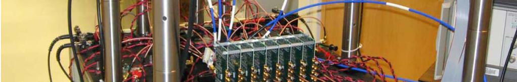
51 mm-wave MIMO: 2-channel prototype, 60 GHz, 40 meters 50mV pe er division 50mV pe er division 500ps per division 500ps per division


52 mm-wave MIMO: 4-channel prototype, 60 GHz, Indoor 4 x 622 Mb/s 60 GHz carrier
53 VSLI for mm-wave & sub-mm-wave systems

54 Billions of 700-GHz Transistors Imaging & Arrays 65 nm CMOS: ~5 db 200 GHz 150 GHz 8 db amplifier 22 nm will be much faster yet. IBM: Janagathan, Pekarik UCSB: Seo What can you do with a few billion 700-GHz transistors? Build Transmitter / Receiver Arrays 100's or 1000's of transmitters or receivers...on < 1 cm 2 IC area...operating at GHz.
55 3-stage 250GHz Amplifier Design IBM: Pekarik, Jaganathan UCSB: M. Seo Designs in Fabrication 32 nm CMOS Fcenter 260GHz Gain 9.9dB P DC 15mW m m37 m db(s(1,2)) db(s(2,1)) f req, GHz m11 freq 260.0GHz db(s(2,1))9.916 db(s(2,2)) db(s(1,1)) f req, GHz m37 m38 freq 260.0GHz freq 260.0GHz db(s(1,1)) db(s(2,2)) StabFactor freq, GHz
56 millimeter-wave spectrum: new solutions needed mm-wave Bands Lots of bandwidth P P received transmitte d 2 1 λ π R e αr short wavelength weak signal short range highly directional antenna strong signal long range 2 P received D td r λ P 2 2 transmitte d π R 16 e α R narrow beam must be aimed no good for mobile monolithic beam steering arrays strong signal, steerable Preceived N N P 16 transmit λ R 2 receive transmit 2 e αr 32 x 32 array db increased SNR vastly increased range multi-gigabit mobile communications
 2 wavelength 2 Arrays for")

57 Billions of 700-GHz Transistors Imaging & Arrays Arrays for point-point i t radio links: bit rate distance 2 (# array elements) 2 wavelength 2 Arrays for (sub)-mm-wave imaging : # resovable pixels # array elements Arrays for Spatial-Division-Multiplexing i i lti l i Networks: # independen t beams # array elements 4 array area wavelength 2
58 THz Transistors
59 Why Build THz Transistors? 500 GHz digital logic fiber optics THz amplifiers THz radios imaging, sensing, communications precision analog design at microwave frequencies high-performance receivers Higher-Resolution Microwave ADCs, DACs, DDSs
60 THz Integrated Circuits Device scaling (Moore's Law) is not yet over. Scaling multi-thz transistors. Challenges in scaling: contacts, dielectrics, heat Multi-THz transistors: for systems at very high frequencies for better performance at moderate frequencies Vast #s of THz transistors complex systems new applications... imaging, radio, and more
61 end
 2 1.34 32 1000 83.5 3 219 2.19 72 4 2.84 128 2 0.42 32 100 83.5 3 0.69 72 4 0.90 128 2 0.16 45 10 60.5 3 0.26 101 4 0.")
62 MIMO Link: a Subsampled Multi-Beam Phased Array array places nulls at interfering transmitters 2 ND λr Range (m) Carrier Frequency (GHz) N Array Length (m) Data Rate 1 (Gb/s) Assuming N x N square arrays
100+ GHz Transistor Electronics: Present and Projected Capabilities
 21 IEEE International Topical Meeting on Microwave Photonics, October 5-6, 21, Montreal 1+ GHz Transistor Electronics: Present and Projected Capabilities Mark Rodwell University of California, Santa Barbara
High-Frequency Transistors High-Frequency ICs. Technologies & Applications
 High-Frequency Transistors High-Frequency ICs Technologies & Applications Mark Rodwell University of California, Santa Barbara rodwell@ece.ucsb.edu 805-893-3244, 805-893-2362 fax Report Documentation Page
Frequency Limits of Bipolar Integrated Circuits
 IEEE MTT-S Symposium, June 13, 2006 Frequency Limits of Bipolar Integrated Circuits Mark Rodwell University of California, Santa Barbara Collaborators Z. Griffith, E. Lind, V. Paidi, N. Parthasarathy,
Frequency Limits of InP-based Integrated Circuits
 Plenary, Indium Phosphide and Related Materials Conference, May 15-18, Matsue, Japan Frequency Limits of InP-based Integrated Circuits Mark Rodwell, E. Lind, Z. Griffith, S. R. Bank, A. M. Crook U. Singisetti,
Galileo, Elephants, & Fast Nano-Devices
 Presentation to NNIN REU interns, July 29, 2008 Galileo, Elephants, & Fast Nano-Devices Mark Rodwell University of California, Santa Barbara rodwell@ece.ucsb.edu 805-893-3244, 805-893-5705 fax Scaling:
Sub-mm-Wave Technologies: Systems, ICs, THz Transistors
 2013 Asia-Pacific Microwave Conference, November 8th, Seoul Sub-mm-Wave Technologies: Systems, ICs, THz Transistors Mark Rodwell University of California, Santa Barbara Coauthors: J. Rode, H.W. Chiang,
Indium Phosphide and Related Materials Selectively implanted subcollector DHBTs
 Indium Phosphide and Related Materials - 2006 Selectively implanted subcollector DHBTs Navin Parthasarathy, Z. Griffith, C. Kadow, U. Singisetti, and M.J.W. Rodwell Dept. of Electrical and Computer Engineering,
THz Indium Phosphide Bipolar Transistor Technology
 IEEE Compound Semiconductor IC Symposium, October 4-7, La Jolla, California THz Indium Phosphide Bipolar Transistor Technology Mark Rodwell University of California, Santa Barbara Coauthors: J. Rode, H.W.
Transistor & IC design for Sub-mm-Wave & THz ICs
 Plenary, 2012 European Microwave Integrated Circuits Conference, October 29th, Amsterdam Transistor & IC design for Sub-mm-Wave & THz ICs Mark Rodwell University of California, Santa Barbara Coauthors:
Optical Phase-Locking and Wavelength Synthesis
 2014 IEEE Compound Semiconductor Integrated Circuits Symposium, October 21-23, La Jolla, CA. Optical Phase-Locking and Wavelength Synthesis M.J.W. Rodwell, H.C. Park, M. Piels, M. Lu, A. Sivananthan, E.
50-500GHz Wireless Technologies: Transistors, ICs, and Systems
 Plenary, Asia-Pacific Microwave Conference, December 6, 2015, Nanjing, China 50-500GHz Wireless Technologies: Transistors, ICs, and Systems Mark Rodwell, UCSB J. Rode*, P. Choudhary, B. Thibeault, W. Mitchell,
Transistors for THz Systems
 IMS Workshop: Technologies for THZ Integrated Systems (WMD) Monday, June 3, 013, Seattle, Washington (8AM-5PM) Transistors for THz Systems Mark Rodwell, UCSB rodwell@ece.ucsb.edu Co-Authors and Collaborators:
30% PAE W-band InP Power Amplifiers using Sub-quarter-wavelength Baluns for Series-connected Power-combining
 2013 IEEE Compound Semiconductor IC Symposium, October 13-15, Monterey, C 30% PAE W-band InP Power Amplifiers using Sub-quarter-wavelength Baluns for Series-connected Power-combining 1 H.C. Park, 1 S.
THz HBTs & sub-mm-wave ICs
 Workshop: Sub-millimeter-wave Monolithic Integrated Circuits. European Microwave Week. Amsterdam, Oct. 28, 2012 THz HBTs & sub-mm-wave ICs Mark Rodwell, UCSB Co-Authors and Collaborators: Teledyne HBT
A 3-Stage Shunt-Feedback Op-Amp having 19.2dB Gain, 54.1dBm OIP3 (2GHz), and 252 OIP3/P DC Ratio
, and 252 OIP3/P DC Ratio") International Microwave Symposium 2011 Chart 1 A 3-Stage Shunt-Feedback Op-Amp having 19.2dB Gain, 54.1dBm OIP3 (2GHz), and 252 OIP3/P DC Ratio Zach Griffith, M. Urteaga, R. Pierson, P. Rowell, M. Rodwell,
International Microwave Symposium 2011 Chart 1 A 3-Stage Shunt-Feedback Op-Amp having 19.2dB Gain, 54.1dBm OIP3 (2GHz), and 252 OIP3/P DC Ratio Zach Griffith, M. Urteaga, R. Pierson, P. Rowell, M. Rodwell,
InP HBT technology development at IEMN
 InP HBT technology development at IEMN Advanced NanOmetric Devices Group, Institut d Electronique de Microelectronique et de Nanotechnology, Lille, FRANCE Date Outline Which applications for THz GaAsSb/InP
TU3B-1. An 81 GHz, 470 mw, 1.1 mm 2 InP HBT Power Amplifier with 4:1 Series Power Combining using Sub-quarter-wavelength Baluns
 TU3B-1 Student Paper Finalist An 81 GHz, 470 mw, 1.1 mm 2 InP HBT Power Amplifier with 4:1 Series Power Combining using Sub-quarter-wavelength Baluns H. Park 1, S. Daneshgar 1, J. C. Rode 1, Z. Griffith
DEFENSE TECHNICAL INFORMATION CENTER
 DEFENSE TECHNICAL INFORMATION CENTER [nformiiioitforthe Deffrtse Couutauuty Month Day Year DTI'C has determined on LL j that this Technical Document has the Distribution Statement checked below. The current
GHz Bipolar ICs: Device and Circuit Design Principles
 Short Course, IEEE Bipolar / BiCMOS Circuits and Technology Meeting, 9 October 2011, Atlanta, Georgia 100-1000 GHz Bipolar ICs: Device and Circuit Design Principles Mark Rodwell, UCSB Munkyo Seo, Teledyne
Millimeter wave MIMO. E. Torkildson, B. Ananthasubramaniam, U. Madhow, M. Rodwell Dept. of Electrical and Computer Engineering
 Millimeter wave MIMO Wireless Links at Optical Speeds E. Torkildson, B. Ananthasubramaniam, U. Madhow, M. Rodwell Dept. of Electrical and Computer Engineering University of California, Santa Barbara The
Record I on (0.50 ma/μm at V DD = 0.5 V and I off = 100 na/μm) 25 nm-gate-length ZrO 2 /InAs/InAlAs MOSFETs
 25 nm-gate-length ZrO 2 /InAs/InAlAs MOSFETs") Record I on (0.50 ma/μm at V DD = 0.5 V and I off = 100 na/μm) 25 nm-gate-length ZrO 2 /InAs/InAlAs MOSFETs Sanghoon Lee 1*, V. Chobpattana 2,C.-Y. Huang 1, B. J. Thibeault 1, W. Mitchell 1, S. Stemmer
Record I on (0.50 ma/μm at V DD = 0.5 V and I off = 100 na/μm) 25 nm-gate-length ZrO 2 /InAs/InAlAs MOSFETs Sanghoon Lee 1*, V. Chobpattana 2,C.-Y. Huang 1, B. J. Thibeault 1, W. Mitchell 1, S. Stemmer
Evaluating and Optimizing Tradeoffs in CMOS RFIC Upconversion Mixer Design. by Dr. Stephen Long University of California, Santa Barbara
 Evaluating and Optimizing Tradeoffs in CMOS RFIC Upconversion Mixer Design by Dr. Stephen Long University of California, Santa Barbara It is not easy to design an RFIC mixer. Different, sometimes conflicting,
ECE 145A / 218 C, notes set xx: Class A power amplifiers
 ECE 145A / 218 C, notes set xx: Class A power amplifiers Mark Rodwell University of California, Santa Barbara rodwell@ece.ucsb.edu 805-893-3244, 805-893-3262 fax Class A power amplifier: what do we mean?
Project: IEEE P Working Group for Wireless Personal Area Networks (WPANs)
") Project: IEEE P802.15 Working Group for Wireless Personal Area Networks (WPANs) Title: Feasibility test of THz channel for high-speed wireless link Date Submitted: 12 Nov 2013 Source: Jae-Young Kim, Ho-Jin
Project: IEEE P802.15 Working Group for Wireless Personal Area Networks (WPANs) Title: Feasibility test of THz channel for high-speed wireless link Date Submitted: 12 Nov 2013 Source: Jae-Young Kim, Ho-Jin
Alternatives to standard MOSFETs. What problems are we really trying to solve?
 Alternatives to standard MOSFETs A number of alternative FET schemes have been proposed, with an eye toward scaling up to the 10 nm node. Modifications to the standard MOSFET include: Silicon-in-insulator
Developing Bipolar Transistors for Sub-mm-Wave Amplifiers and Next-Generation (300 GHz) Digital Circuits
 Digital Circuits") Plenary, Device Research Conerence, State College, PA, June 26, 26 Developing Bipolar Transistors or Sub-mm-Wave Ampliiers and Next-Generation (3 GHz) Digital Circuits Mark Rodwell University o Caliornia,
Plenary, Device Research Conerence, State College, PA, June 26, 26 Developing Bipolar Transistors or Sub-mm-Wave Ampliiers and Next-Generation (3 GHz) Digital Circuits Mark Rodwell University o Caliornia,
GaN MMIC PAs for MMW Applicaitons
 GaN MMIC PAs for MMW Applicaitons Miroslav Micovic HRL Laboratories LLC, 311 Malibu Canyon Road, Malibu, CA 9265, U. S. A. mmicovic@hrl.com Motivation for High Frequency Power sources 6 GHz 11 GHz Frequency
MICROWAVE ENGINEERING-II. Unit- I MICROWAVE MEASUREMENTS
 MICROWAVE ENGINEERING-II Unit- I MICROWAVE MEASUREMENTS 1. Explain microwave power measurement. 2. Why we can not use ordinary diode and transistor in microwave detection and microwave amplification? 3.
ISSCC 2004 / SESSION 26 / OPTICAL AND FAST I/O / 26.4
 ISSCC 2004 / SESSION 26 / OPTICAL AND FAST I/O / 26.4 26.4 40Gb/s CMOS Distributed Amplifier for Fiber-Optic Communication Systems H. Shigematsu 1, M. Sato 1, T. Hirose 1, F. Brewer 2, M. Rodwell 2 1 Fujitsu,
Up to 6 GHz Low Noise Silicon Bipolar Transistor Chip. Technical Data AT-41400
 Up to 6 GHz Low Noise Silicon Bipolar Transistor Chip Technical Data AT-1 Features Low Noise Figure: 1.6 db Typical at 3. db Typical at. GHz High Associated Gain: 1.5 db Typical at 1.5 db Typical at. GHz
Planarization and Regrowth of Self-Aligned Ohmic Contacts on InGaAs
 MBE 2008, Vancouver, B.C. Planarization and Regrowth of Self-Aligned Ohmic Contacts on InGaAs Mark Wistey, Greg Burek, Uttam Singisetti, Austin Nelson, Brian Thibeault, Joël Cagnon, Susanne Stemmer, Arthur
Single-stage G-band HBT Amplifier with 6.3 db Gain at 175 GHz
 Single-stage G-band HBT Amplifier with 6.3 db Gain at 175 GHz M. Urteaga, D. Scott, T. Mathew, S. Krishnan, Y. Wei, M.J.W. Rodwell Department of Electrical and Computer Engineering, University of California,
Quantum-effect Resonant Tunneling Device Technology for Practical Ultra Low-power High-speed Applications
 Quantum-effect Resonant Tunneling Device Technology for Practical Ultra Low-power High-speed Applications SEMATECH Symposium October 23 rd, 2012 Prof. Kyounghoon Yang High Speed Nanoelectronics Laboratory
Full H-band Waveguide-to-Coupled Microstrip Transition Using Dipole Antenna with Directors
 IEICE Electronics Express, Vol.* No.*,*-* Full H-band Waveguide-to-Coupled Microstrip Transition Using Dipole Antenna with Directors Wonseok Choe, Jungsik Kim, and Jinho Jeong a) Department of Electronic
Signal Integrity Design of TSV-Based 3D IC
 Signal Integrity Design of TSV-Based 3D IC October 24, 21 Joungho Kim at KAIST joungho@ee.kaist.ac.kr http://tera.kaist.ac.kr 1 Contents 1) Driving Forces of TSV based 3D IC 2) Signal Integrity Issues
Field Effect Transistors
 Field Effect Transistors Purpose In this experiment we introduce field effect transistors (FETs). We will measure the output characteristics of a FET, and then construct a common-source amplifier stage,
Optical Fiber Communication Lecture 11 Detectors
 Optical Fiber Communication Lecture 11 Detectors Warriors of the Net Detector Technologies MSM (Metal Semiconductor Metal) PIN Layer Structure Semiinsulating GaAs Contact InGaAsP p 5x10 18 Absorption InGaAs
A 1.1V 150GHz Amplifier with 8dB Gain and +6dBm Saturated Output Power in Standard Digital 65nm CMOS Using Dummy-Prefilled Microstrip Lines
 A 1.1V 150GHz Amplifier with 8dB Gain and +6dBm Saturated Output Power in Standard Digital 65nm CMOS Using Dummy-Prefilled Microstrip Lines M. Seo 1, B. Jagannathan 2, C. Carta 1, J. Pekarik 3, L. Chen
Up to 6 GHz Medium Power Silicon Bipolar Transistor. Technical Data AT Plastic Package
 Up to 6 GHz Medium Power Silicon Bipolar Transistor Technical Data AT-286 Features High Output Power: 2.5 dbm Typical P 1 db at 2. GHz High Gain at 1 db Compression: 13.5 db Typical G 1 db at 2. GHz Low
Design of THz Signal Generation Circuits Using 65nm CMOS Technologies
 Design of THz Signal Generation Circuits Using 65nm CMOS Technologies Hyeong-Jin Kim, Wonseok Choe, and Jinho Jeong Department of Electronics Engineering, Sogang University E-mail: jjeong@sogang.ac.kr
Surface Mount Low Noise Silicon Bipolar Transistor Chip. Technical Data AT-41411
 Surface Mount Low Noise Silicon Bipolar Transistor Chip Technical Data AT-111 Features Low Noise Figure: 1. db Typical at 1. GHz 1.8 db Typical at 2. GHz High Associated Gain: 18. db Typical at 1. GHz
ECE520 VLSI Design. Lecture 2: Basic MOS Physics. Payman Zarkesh-Ha
 ECE520 VLSI Design Lecture 2: Basic MOS Physics Payman Zarkesh-Ha Office: ECE Bldg. 230B Office hours: Wednesday 2:00-3:00PM or by appointment E-mail: pzarkesh@unm.edu Slide: 1 Review of Last Lecture Semiconductor
Record Extrinsic Transconductance (2.45 ms/μm at V DS = 0.5 V) InAs/In 0.53 Ga 0.47 As Channel MOSFETs Using MOCVD Source-Drain Regrowth
 InAs/In 0.53 Ga 0.47 As Channel MOSFETs Using MOCVD Source-Drain Regrowth") Record Extrinsic Transconductance (2.45 ms/μm at = 0.5 V) InAs/In 0.53 Ga 7 As Channel MOSFETs Using MOCVD Source-Drain Regrowth Sanghoon Lee 1*, C.-Y. Huang 1, A. D. Carter 1, D. C. Elias 1, J. J. M.
Record Extrinsic Transconductance (2.45 ms/μm at = 0.5 V) InAs/In 0.53 Ga 7 As Channel MOSFETs Using MOCVD Source-Drain Regrowth Sanghoon Lee 1*, C.-Y. Huang 1, A. D. Carter 1, D. C. Elias 1, J. J. M.
High Power Wideband AlGaN/GaN HEMT Feedback. Amplifier Module with Drain and Feedback Loop. Inductances
 High Power Wideband AlGaN/GaN HEMT Feedback Amplifier Module with Drain and Feedback Loop Inductances Y. Chung, S. Cai, W. Lee, Y. Lin, C. P. Wen, Fellow, IEEE, K. L. Wang, Fellow, IEEE, and T. Itoh, Fellow,
Figure Responsivity (A/W) Figure E E-09.
 Figure E E-09.") OSI Optoelectronics, is a leading manufacturer of fiber optic components for communication systems. The products offer range for Silicon, GaAs and InGaAs to full turnkey solutions. Photodiodes are semiconductor
OSI Optoelectronics, is a leading manufacturer of fiber optic components for communication systems. The products offer range for Silicon, GaAs and InGaAs to full turnkey solutions. Photodiodes are semiconductor
Adaptive Spatial Multiplexing for Millimeter-Wave Communication Links
 UNIVERSITY OF CALIFORNIA Santa Barbara Adaptive Spatial Multiplexing for Millimeter-Wave Communication Links A Dissertation submitted in partial satisfaction of the requirements for the degree of Doctor
6.012 Microelectronic Devices and Circuits
 Page 1 of 13 YOUR NAME Department of Electrical Engineering and Computer Science Massachusetts Institute of Technology 6.012 Microelectronic Devices and Circuits Final Eam Closed Book: Formula sheet provided;
Capacitive-Division Traveling-Wave Amplifier with 340 GHz Gain-Bandwidth Product
 Hughes Presented at the 1995 IEEE MTT-S Symposium UCSB Capacitive-Division Traveling-Wave Amplifier with 340 GHz Gain-Bandwidth Product J. Pusl 1,2, B. Agarwal1, R. Pullela1, L. D. Nguyen 3, M. V. Le 3,
BJT Amplifier. Superposition principle (linear amplifier)
") BJT Amplifier Two types analysis DC analysis Applied DC voltage source AC analysis Time varying signal source Superposition principle (linear amplifier) The response of a linear amplifier circuit excited
BJT Amplifier Two types analysis DC analysis Applied DC voltage source AC analysis Time varying signal source Superposition principle (linear amplifier) The response of a linear amplifier circuit excited
Gallium nitride (GaN)
") 80 Technology focus: GaN power electronics Vertical, CMOS and dual-gate approaches to gallium nitride power electronics US research company HRL Laboratories has published a number of papers concerning
80 Technology focus: GaN power electronics Vertical, CMOS and dual-gate approaches to gallium nitride power electronics US research company HRL Laboratories has published a number of papers concerning
In0.53Ga0.47As MOSFETs with 5 nm channel and self-aligned source/drain by MBE regrowth
 UNIVERSITY OF CALIFORNIA Santa Barbara In0.53Ga0.47As MOSFETs with 5 nm channel and self-aligned source/drain by MBE regrowth A Dissertation submitted in partial satisfaction of the requirements for the
A 1-W GaAs Class-E Power Amplifier with an FBAR Filter Embedded in the Output Network
 A 1-W GaAs Class-E Power Amplifier with an FBAR Filter Embedded in the Output Network Kyle Holzer and Jeffrey S. Walling University of Utah PERFIC Lab, Salt Lake City, UT 84112, USA Abstract Integration
Introduction to VLSI ASIC Design and Technology
 Introduction to VLSI ASIC Design and Technology Paulo Moreira CERN - Geneva, Switzerland Paulo Moreira Introduction 1 Outline Introduction Is there a limit? Transistors CMOS building blocks Parasitics
An Inductor-Based 52-GHz 0.18 µm SiGe HBT Cascode LNA with 22 db Gain
 An Inductor-Based 52-GHz 0.18 µm SiGe HBT Cascode LNA with 22 db Gain Michael Gordon, Sorin P. Voinigescu University of Toronto Toronto, Ontario, Canada ESSCIRC 2004, Leuven, Belgium Outline Motivation
4.2.2 Metal Oxide Semiconductor Field Effect Transistor (MOSFET)
") 4.2.2 Metal Oxide Semiconductor Field Effect Transistor (MOSFET) The Metal Oxide Semitonductor Field Effect Transistor (MOSFET) has two modes of operation, the depletion mode, and the enhancement mode.
4.2.2 Metal Oxide Semiconductor Field Effect Transistor (MOSFET) The Metal Oxide Semitonductor Field Effect Transistor (MOSFET) has two modes of operation, the depletion mode, and the enhancement mode.
65-GHz Receiver in SiGe BiCMOS Using Monolithic Inductors and Transformers
 65-GHz Receiver in SiGe BiCMOS Using Monolithic Inductors and Transformers Michael Gordon, Terry Yao, Sorin P. Voinigescu University of Toronto March 10 2006, UBC, Vancouver Outline Motivation mm-wave
RF and Microwave Semiconductor Technologies
 RF and Microwave Semiconductor Technologies Muhammad Fahim Ul Haque, Department of Electrical Engineering, Linköping University muhha@isy.liu.se Note: 1. This presentation is for the course of State of
An 18-GHz Continuous-Time 6 1 Analog Digital Converter Implemented in InP-Transferred Substrate HBT Technology
 IEEE JOURNAL OF SOLID-STATE CIRCUITS, VOL. 36, NO. 9, SEPTEMBER 2001 1343 An 18-GHz Continuous-Time 6 1 Analog Digital Converter Implemented in InP-Transferred Substrate HBT Technology Shrinivasan Jaganathan,
High Performance Mixed Signal Circuits Enabled by the Direct Monolithic Heterogeneous Integration of InP HBT and Si CMOS on a Silicon Substrate
 High Performance Mixed Signal Circuits Enabled by the Direct Monolithic Heterogeneous Integration of InP HBT and Si CMOS on a Silicon Substrate The MIT Faculty has made this article openly available. Please
Project: IEEE P Working Group for Wireless Personal Area Networks N
 July, 2008 Project: IEEE P802.15 Working Group for Wireless Personal Area Networks N (WPANs( WPANs) Submission Title: Millimeter-wave Photonics for High Data Rate Wireless Communication Systems Date Submitted:
Figure Figure E E-09. Dark Current (A) 1.
 1.") OSI Optoelectronics, is a leading manufacturer of fiber optic components for communication systems. The products offer range for Silicon, GaAs and InGaAs to full turnkey solutions. Photodiodes are semiconductor
OSI Optoelectronics, is a leading manufacturer of fiber optic components for communication systems. The products offer range for Silicon, GaAs and InGaAs to full turnkey solutions. Photodiodes are semiconductor
Analog Electronics. Electronic Devices, 9th edition Thomas L. Floyd Pearson Education. Upper Saddle River, NJ, All rights reserved.
 Analog Electronics BJT Structure The BJT has three regions called the emitter, base, and collector. Between the regions are junctions as indicated. The base is a thin lightly doped region compared to the
techniques, and gold metalization in the fabrication of this device.
 Up to 6 GHz Medium Power Silicon Bipolar Transistor Chip Technical Data AT-42 Features High Output Power: 21. dbm Typical P 1 db at 2. GHz 2.5 dbm Typical P 1 db at 4. GHz High Gain at 1 db Compression:
UNIT 3 Transistors JFET
 UNIT 3 Transistors JFET Mosfet Definition of BJT A bipolar junction transistor is a three terminal semiconductor device consisting of two p-n junctions which is able to amplify or magnify a signal. It
MTLE-6120: Advanced Electronic Properties of Materials. Semiconductor transistors for logic and memory. Reading: Kasap
 MTLE-6120: Advanced Electronic Properties of Materials 1 Semiconductor transistors for logic and memory Reading: Kasap 6.6-6.8 Vacuum tube diodes 2 Thermionic emission from cathode Electrons collected
THz communications: general issues THz devices for coms (Tx and Rx) Some Reported com links Some conclusions
 Some Reported com links Some conclusions") THz communications for next generation HD rate wireless links TENXSYS Talk, 2015, June 17th G. Ducournau, M. Zaknoune, P. Szriftgiser, Jean-François Lampin (Tx and Rx) (Tx and Rx) 2 3 THz coms: general
THz communications for next generation HD rate wireless links TENXSYS Talk, 2015, June 17th G. Ducournau, M. Zaknoune, P. Szriftgiser, Jean-François Lampin (Tx and Rx) (Tx and Rx) 2 3 THz coms: general
Special Issue Review. 1. Introduction
 Special Issue Review In recently years, we have introduced a new concept of photonic antennas for wireless communication system using radio-over-fiber technology. The photonic antenna is a functional device
Review Energy Bands Carrier Density & Mobility Carrier Transport Generation and Recombination
 Review Energy Bands Carrier Density & Mobility Carrier Transport Generation and Recombination Current Transport: Diffusion, Thermionic Emission & Tunneling For Diffusion current, the depletion layer is
Difference between BJTs and FETs. Junction Field Effect Transistors (JFET)
") Difference between BJTs and FETs Transistors can be categorized according to their structure, and two of the more commonly known transistor structures, are the BJT and FET. The comparison between BJTs
Difference between BJTs and FETs Transistors can be categorized according to their structure, and two of the more commonly known transistor structures, are the BJT and FET. The comparison between BJTs
insert link to the published version of your paper
 Citation Niels Van Thienen, Wouter Steyaert, Yang Zhang, Patrick Reynaert, (215), On-chip and In-package Antennas for mm-wave CMOS Circuits Proceedings of the 9th European Conference on Antennas and Propagation
Semiconductor Memory: DRAM and SRAM. Department of Electrical and Computer Engineering, National University of Singapore
 Semiconductor Memory: DRAM and SRAM Outline Introduction Random Access Memory (RAM) DRAM SRAM Non-volatile memory UV EPROM EEPROM Flash memory SONOS memory QD memory Introduction Slow memories Magnetic
RF Module for High-Resolution Infrastructure Radars
 FEATURED TOPIC Module for High-Resolution Infrastructure Radars Osamu ANEGAWA*, Akira OTSUKA, Takeshi KAWASAKI, Koji TSUKASHIMA, Miki KUBOTA, and Takashi NAKABAYASHI ----------------------------------------------------------------------------------------------------------------------------------------------------------------------------------------------------------------------------------------------------------
Active Technology for Communication Circuits
 EECS 242: Active Technology for Communication Circuits UC Berkeley EECS 242 Copyright Prof. Ali M Niknejad Outline Comparison of technology choices for communication circuits Si npn, Si NMOS, SiGe HBT,
ECE145a / 218a: Notes Set 5 device models & device characteristics:
 ECE145a / 218a: Notes Set 5 device models & device characteristics: Mark odwell University of California, Santa Barbara rodwell@ece.ucsb.edu 805-893-3244, 805-893-3262 fax Content: Bipolar Transistor M
Integrated diodes. The forward voltage drop only slightly depends on the forward current. ELEKTRONIKOS ĮTAISAI
 1 Integrated diodes pn junctions of transistor structures can be used as integrated diodes. The choice of the junction is limited by the considerations of switching speed and breakdown voltage. The forward
AT Up to 6 GHz Medium Power Silicon Bipolar Transistor. Data Sheet
 AT-86 Up to 6 GHz Medium Power Silicon Bipolar Transistor Data Sheet Description Avago s AT-86 is a general purpose NPN bipolar transistor that offers excellent high frequency performance. The AT-86 is
Simulations of High Linearity and High Efficiency of Class B Power Amplifiers in GaN HEMT Technology
 Simulations of High Linearity and High Efficiency of Class B Power Amplifiers in GaN HEMT Technology Vamsi Paidi, Shouxuan Xie, Robert Coffie, Umesh K Mishra, Stephen Long, M J W Rodwell Department of
Week 7: Common-Collector Amplifier, MOS Field Effect Transistor
 EE 2110A Electronic Circuits Week 7: Common-Collector Amplifier, MOS Field Effect Transistor ecture 07-1 Topics to coer Common-Collector Amplifier MOS Field Effect Transistor Physical Operation and I-V
Integration of Optoelectronic and RF Devices for Applications in Optical Interconnect and Wireless Communication
 Integration of Optoelectronic and RF Devices for Applications in Optical Interconnect and Wireless Communication Zhaoran (Rena) Huang Assistant Professor Department of Electrical, Computer and System Engineering
57-65GHz CMOS Power Amplifier Using Transformer-Coupling and Artificial Dielectric for Compact Design
 57-65GHz CMOS Power Amplifier Using Transformer-Coupling and Artificial Dielectric for Compact Design Tim LaRocca, and Frank Chang PA Symposium 1/20/09 Overview Introduction Design Overview Differential
Wideband Reconfigurable Harmonically Tuned GaN SSPA for Cognitive Radios
 The University Of Cincinnati College of Engineering Wideband Reconfigurable Harmonically Tuned GaN SSPA for Cognitive Radios Seth W. Waldstein The University of Cincinnati-Main Campus Miguel A. Barbosa
EXAMINATION FOR THE DEGREE OF B.E. and M.E. Semester
 EXAMINATION FOR THE DEGREE OF B.E. and M.E. Semester 2 2009 101908 OPTICAL COMMUNICATION ENGINEERING (Elec Eng 4041) 105302 SPECIAL STUDIES IN MARINE ENGINEERING (Elec Eng 7072) Official Reading Time:
Acknowledgements. Curriculum Vitæ. List of Figures. List of Tables. 1 Introduction Si MOSFET Scaling... 2
 Contents Acknowledgements Curriculum Vitæ Abstract List of Figures List of Tables v vi viii xii xviii 1 Introduction 1 1.1 Si MOSFET Scaling......................... 2 2 General MOSFET Scaling Theory 7
SRM INSTITUTE OF SCIENCE AND TECHNOLOGY (DEEMED UNIVERSITY)
") SRM INSTITUTE OF SCIENCE AND TECHNOLOGY (DEEMED UNIVERSITY) QUESTION BANK I YEAR B.Tech (II Semester) ELECTRONIC DEVICES (COMMON FOR EC102, EE104, IC108, BM106) UNIT-I PART-A 1. What are intrinsic and
SRM INSTITUTE OF SCIENCE AND TECHNOLOGY (DEEMED UNIVERSITY) QUESTION BANK I YEAR B.Tech (II Semester) ELECTRONIC DEVICES (COMMON FOR EC102, EE104, IC108, BM106) UNIT-I PART-A 1. What are intrinsic and
1-13GHz Wideband LNA utilizing a Transformer as a Compact Inter-stage Network in 65nm CMOS
 -3GHz Wideband LNA utilizing a Transformer as a Compact Inter-stage Network in 65nm CMOS Hyohyun Nam and Jung-Dong Park a Division of Electronics and Electrical Engineering, Dongguk University, Seoul E-mail
Optically reconfigurable balanced dipole antenna
 Loughborough University Institutional Repository Optically reconfigurable balanced dipole antenna This item was submitted to Loughborough University's Institutional Repository by the/an author. Citation:
Examination Optoelectronic Communication Technology. April 11, Name: Student ID number: OCT1 1: OCT 2: OCT 3: OCT 4: Total: Grade:
 Examination Optoelectronic Communication Technology April, 26 Name: Student ID number: OCT : OCT 2: OCT 3: OCT 4: Total: Grade: Declaration of Consent I hereby agree to have my exam results published on
A 7-GHz 1.8-dB NF CMOS Low-Noise Amplifier
 852 IEEE JOURNAL OF SOLID-STATE CIRCUITS, VOL. 37, NO. 7, JULY 2002 A 7-GHz 1.8-dB NF CMOS Low-Noise Amplifier Ryuichi Fujimoto, Member, IEEE, Kenji Kojima, and Shoji Otaka Abstract A 7-GHz low-noise amplifier
ANALYSIS AND DESIGN OF ANALOG INTEGRATED CIRCUITS
 ANALYSIS AND DESIGN OF ANALOG INTEGRATED CIRCUITS Fourth Edition PAUL R. GRAY University of California, Berkeley PAUL J. HURST University of California, Davis STEPHEN H. LEWIS University of California,
mhemt based MMICs, Modules, and Systems for mmwave Applications Axel Hülsmann Axel Tessmann Jutta Kühn Oliver Ambacher
 mhemt based MMICs, Modules, and Systems for mmwave Applications Christaweg 54 79114 Freiburg, Germany +49 761 5951 4692 info@ondosense.com www.ondosense.com Axel Hülsmann Axel Tessmann Jutta Kühn Oliver
Silicon Photonics in Optical Communications. Lars Zimmermann, IHP, Frankfurt (Oder), Germany
, Germany") Silicon Photonics in Optical Communications Lars Zimmermann, IHP, Frankfurt (Oder), Germany Outline IHP who we are Silicon photonics Photonic-electronic integration IHP photonic technology Conclusions
Silicon Photonics in Optical Communications Lars Zimmermann, IHP, Frankfurt (Oder), Germany Outline IHP who we are Silicon photonics Photonic-electronic integration IHP photonic technology Conclusions
CHAPTER 6 CARBON NANOTUBE AND ITS RF APPLICATION
 CHAPTER 6 CARBON NANOTUBE AND ITS RF APPLICATION 6.1 Introduction In this chapter we have made a theoretical study about carbon nanotubes electrical properties and their utility in antenna applications.
A Miniaturized Multi-Channel TR Module Design Based on Silicon Substrate
 Progress In Electromagnetics Research Letters, Vol. 74, 117 123, 2018 A Miniaturized Multi-Channel TR Module Design Based on Silicon Substrate Jun Zhou 1, 2, *, Jiapeng Yang 1, Donglei Zhao 1, and Dongsheng
Coherent Receivers Principles Downconversion
 Coherent Receivers Principles Downconversion Heterodyne receivers mix signals of different frequency; if two such signals are added together, they beat against each other. The resulting signal contains
Student Lecture by: Giangiacomo Groppi Joel Cassell Pierre Berthelot September 28 th 2004
 Student Lecture by: Giangiacomo Groppi Joel Cassell Pierre Berthelot September 28 th 2004 Lecture outline Historical introduction Semiconductor devices overview Bipolar Junction Transistor (BJT) Field
Analog Circuits and Systems
 Analog Circuits and Systems Prof. K Radhakrishna Rao Lecture 10: Electronic Devices for Analog Circuits 1 Multipliers Multipliers provide multiplication of two input voltages or currents Multipliers can
DISCRETE SEMICONDUCTORS DATA SHEET. BLW98 UHF linear power transistor
 DISCRETE SEMICONDUCTORS DATA SHEET August 1986 DESCRIPTION N-P-N silicon planar epitaxial transistor primarily intended for use in linear u.h.f. amplifiers of TV transposers and transmitters in band IV-V,
Advances in Microwave & Millimeterwave Integrated Circuits
 الراديو - جامعة Advances in Microwave & Millimeterwave Integrated Circuits الهندسة آلية عين شمس ١٥ مارس ٢٠٠٧-١٣ Amin K. Ezzeddine AMCOM Communications, Inc. 22300 Comsat Drive Clarksburg, Maryland 20871,
Fully integrated CMOS transmitter design considerations
 Semiconductor Technology Fully integrated CMOS transmitter design considerations Traditionally, multiple IC chips are needed to build transmitters (Tx) used in wireless communications. The difficulty with
InGaAs Nanoelectronics: from THz to CMOS
 InGaAs Nanoelectronics: from THz to CMOS J. A. del Alamo Microsystems Technology Laboratories, MIT IEEE International Conference on Electron Devices and Solid-State Circuits Hong Kong, June 3, 2013 Acknowledgements: