PRESENTATION ON 555 TIMER A Practical Approach
|
|
|
- James Hubbard
- 6 years ago
- Views:
Transcription
1 PRESENTATION ON 555 TIMER A Practical Approach By Nagaraj Vannal Assistant Professor School of Electronics Engineering, K.L.E Technological University, Hubballi-31 nagaraj_vannal@bvb.edu

2 555 Timer The 555 Timer is one of the most popular and versatile integrated circuits ever produced! It is 30 years old and still being used! It is a combination of digital and analog circuits. It is known as the time machine as it performs a wide variety of timing tasks. Applications for the 555 Timer include: Bounce-free switches and Cascaded timers Frequency dividers Voltage-controlled oscillators Pulse generators and LED flashers

3 555 Timer Digital Circuits(15EECC203) Pin 1. Ground, The ground pin connects the 555 timer to the negative (0v) supply rail. Pin 2. Trigger, The negative input to comparator No 1. A negative pulse on this pin sets the internal Flip-flop when the voltage drops below 1/3Vcc causing the output to switch from a LOW to a HIGH state. Pin 3. Output, The output pin can drive any TTL circuit and is capable of sourcing or sinking up to 200mA of current at an output voltage equal to approximately Vcc 1.5V so small speakers, LEDs or motors can be connected directly to the output. Pin 4. Reset, This pin is used to reset the internal Flip-flop controlling the state of the output, pin 3. This is an active-low input and is generally connected to a logic 1 level when not used to prevent any unwanted resetting of the output. Pin 5. Control Voltage, This pin controls the timing of the 555 by overriding the 2/3Vcc level of the voltage divider network. By applying a voltage to this pin the width of the output signal can be varied independently of the RC timing network. When not used it is connected to ground via a 10nF capacitor to eliminate any noise. Pin 6. Threshold, The positive input to comparator No 2. This pin is used to reset the Flip-flop when the voltage applied to it exceeds 2/3Vcc causing the output to switch from HIGH to LOW state. This pin connects directly to the RC timing circuit. Pin 7. Discharge, The discharge pin is connected directly to the Collector of an internal NPN transistor which is used to discharge the timing capacitor to ground when the output at pin 3 switches LOW. Pin 8. Supply +Vcc, This is the power supply pin and for general purpose TTL 555 timers is between 4.5V and 15V.
4 Inside the 555 Timer Digital Circuits(15EECC203)
5 Inside the 555 Timer Digital Circuits(15EECC203) You will learn more about these components later in the course, for now just understand the following: The voltage divider has three equal 5K resistors. It divides the input voltage (Vcc) into three equal parts. The two comparators are op-amps which compare the voltages at their inputs and saturate depending upon which is greater. The flip-flop is a bi-stable device. It generates two values, a high value equal to Vcc and a low value equal to 0V. The transistor is being used as a switch, it connects pin 7 (discharge) to ground when it is closed.
6 Periodic Pulse Train from a 555 Timer 555-Timers, like op-amps can be configured in different ways to create different circuits. We will now look into how this one creates a train of equal pulses, as shown at the output.
7 First we must examine how capacitors charge 10V TCLOSE = U1 V V R1 1k V 8V 1 10V V1 2 U2 TOPEN = 0 C1 1uF 6V 4V Capacitor Voltage 2V 0 Capacitor C1 is charged up by current flowing through R1 I V1 V R1 0V 0s 1ms 2ms 3ms 4ms 5ms 6ms 7ms 8ms 9ms 10ms V(U2:1) V(R1:2) V(V1:+) CAPACITOR 10 V 1k CAPACITOR As the capacitor charges up, its voltage increases and the current charging it decreases, resulting in the charging rate shown Time
8 Capacitor Charging Equations 10mA 10V 8mA 8V 6mA Capacitor and Resistor Current 6V Capacitor Voltage 4mA 4V 2mA 2V 0A 0s 1ms 2ms 3ms 4ms 5ms 6ms 7ms 8ms 9ms 10ms I(R1) I(C1) Capacitor Current Capacitor Voltage Time I 0V 0s 1ms 2ms 3ms 4ms 5ms 6ms 7ms 8ms 9ms 10ms V(U2:1) V(R1:2) V(V1:+) I e o t V V e o t 1 Time Where the time constant RC R1 C1 1ms
9 Understanding the equations 10V 8V 6V Capacitor Voltage 4V 2V 0V 0s 1ms 2ms 3ms 4ms 5ms 6ms 7ms 8ms 9ms 10ms V(U2:1) V(R1:2) V(V1:+) Time Note that the voltage rises to a little above 6V in 1ms. 1 ( 1 e ). 632


10 Capacitor Charging and Discharging There is a good description of capacitor charging and its use in 555 timer circuits at
11 555 Timer At the beginning of the cycle, C1 is charged through resistors R1 and R2. The charging time constant is ( R1 R2) C1 The voltage reaches (2/3)Vcc in a time ( R1 R2) C1
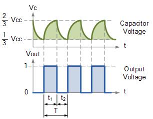
12 555 Timer When the voltage on the capacitor reaches (2/3)Vcc, a switch (the transistor) is closed at pin 7 and the capacitor is discharged to (1/3)Vcc, at which time the switch is opened and the cycle starts over
13 555 Timer The capacitor voltage cycles back and forth between (2/3)Vcc and (1/3)Vcc at times and ( R1 R2) C ( R2) C1 13
14 555 Timer The frequency is then given by f ( R1 2 R2) C1 ( R1 2 R2) C1
15 Types of 555-Timer Circuits 5V 5V Ra 4 8 R 4 8 C Rb uF DIS TH R TR R CV NE555 1 GND VCC Q 3 LED 1 2 1K C uF DIS THR TR R CV NE555 1 GND VCC Q 3 LED Astable Multivibrator puts out a continuous sequence of pulses Monostable Multivibrator (or one-shot) puts out one pulse each time the switch is connected 15
16 Monostable Multivibrator (One Shot) V cc 8 4 Reset R a 6 Trigger 2 2 V cc 3 1 Vcc 3 R R Threshold Comparator +V - + -V +V - + -V Trigger Comparator R Q S Q Control Flip-Flop Output 3 C 7 R 1 Monstable Multivibrator One-Shot
17 Behavior of the Monostable Multivibrator The monostable multivibrator is constructed by adding an external capacitor and resistor to a 555 timer. The circuit generates a single pulse of desired duration when it receives a trigger signal, hence it is also called a one-shot. The time constant of the resistor-capacitor combination determines the length of the pulse.
18 Uses of the Monostable Multivibrator Used to generate a clean pulse of the correct height and duration for a digital system Used to turn circuits or external components on or off for a specific length of time. Used to generate delays. Can be cascaded to create a variety of sequential timing pulses. These pulses can allow you to time and sequence a number of related operations.
19 Astable Pulse-Train Generator (Multivibrator) V cc 8 4 R Threshold Comparator R 1 R 2 6 R - + +V -V R Q Output V -V S Q Trigger Comparator Control Flip-Flop C 7 R 1 Astable Pulse-Train Generator
20 Behavior of the Astable Multivibrator The astable multivibrator is simply an oscillator. The astable multivibrator generates a continuous stream of rectangular off-on pulses that switch between two voltage levels. The frequency of the pulses and their duty cycle are dependent upon the RC network values. The capacitor C charges through the series resistors R 1 and R 2 with a time constant (R 1 + R 2 )C. The capacitor discharges through R 2 with a time constant of R 2 C
21 ton=0.693(r1+r2)c1 toff=0693*r2*c1 T=ton+toff ASTABLE CALCULATIONS FOR LAB Let c1=5uf and For given frequency of 21hz, duty cycle of 64% F=1/T=1/21=48msec Duty cycle=ton/t* =ton/48msec ton=31msec Using toff =17msec => r2=5kω r1=4kω Final Values: R1=4K, R2=5K, C1=5uF Digital Circuits(15EECC203)
22 ASTABLE CALCULATIONS FOR LAB Let c1=1uf and For given frequency of 1hz, duty cycle of 64% ton=0.693(r1+r2)c1 toff=0.693*r2*c1 T=ton+toff F=1/T=1/1=1sec Duty cycle=ton/t* =ton/1sec ton=0.64sec Using toff =0.36sec Final Values: => r2=0.5mω R1=0.5M, R2=0.1M, r1=0.14mω C1=1uF

23 Input Outputs of 555
24 Design for 1sec delay with 50% duty Cycle
25 Design for 1sec delay with 50% duty Cycle Use diode(in4001) across R2 ton=toff=0.693(r1)c1 Choose the c1 value Calculate the r1 with ton=toff=0.5sec R1=R2=calculated value C1=assumed value
26 Design for 1sec delay with 50% duty Cycle Use diode(in4001) across R2 ton=toff=0.693(r1)c1 Choose the c1 Calculate the r1 with ton=toff=0.5sec R1=R2=calculated value = 7.2K C1=assumed value=100uf
PHYS225 Lecture 18. Electronic Circuits
 PHYS225 Lecture 18 Electronic Circuits Oscillators and Timers Oscillators & Timers Produce timing signals to initiate measurement Periodic or single pulse Periodic output at known (controlled) frequency
Electronic Instrumentation
 5V 1 1 1 2 9 10 7 CL CLK LD TE PE CO 15 + 6 5 4 3 P4 P3 P2 P1 Q4 Q3 Q2 Q1 11 12 13 14 2-14161 Electronic Instrumentation Experiment 7 Digital Logic Devices and the 555 Timer Part A: Basic Logic Gates Part
555 Timer and Its Application
 ANALOG ELECTRONICS (AE) 555 Timer and Its Application 1 Prepared by: BE-EE Amish J. Tankariya SEMESTER-III SUBJECT- ANALOG ELECTRONICS (AE) GTU Subject Code :- 210902 2 OBJECTIVES 555 timer; What is the
Multivibrators. Department of Electrical & Electronics Engineering, Amrita School of Engineering
 Multivibrators Multivibrators Multivibrator is an electronic circuit that generates square, rectangular, pulse waveforms. Also called as nonlinear oscillators or function generators. Multivibrator is basically
Introduction to IC-555. Compiled By: Chanakya Bhatt EE, IT-NU
 Introduction to IC-555 Compiled By: Chanakya Bhatt EE, IT-NU Introduction SE/NE 555 is a Timer IC introduced by Signetics Corporation in 1970 s. It is basically a monolithic timing circuit that produces
DEPARTMENT OF ELECTRICAL ENGINEERING LAB WORK EE301 ELECTRONIC CIRCUITS
 DEPARTMENT OF ELECTRICAL ENGINEERING LAB WORK EE301 ELECTRONIC CIRCUITS EXPERIMENT : 4 TITLE : 555 TIMERS OUTCOME : Upon completion of this unit, the student should be able to: 1. gain experience with
ASTABLE MULTIVIBRATOR
 555 TIMER ASTABLE MULTIIBRATOR MONOSTABLE MULTIIBRATOR 555 TIMER PHYSICS (LAB MANUAL) PHYSICS (LAB MANUAL) 555 TIMER Introduction The 555 timer is an integrated circuit (chip) implementing a variety of
EG572EX: ELECTRONIC CIRCUITS I 555 TIMERS
 EG572EX: ELECTRONIC CIRCUITS I 555 TIMERS Prepared By: Ajay Kumar Kadel, Kathmandu Engineering College 1) PIN DESCRIPTIONS Fig.1 555 timer Pin Configurations Pin 1 (Ground):- All voltages are measured
CHAPTER 4: 555 TIMER. Dr. Wan Mahani Hafizah binti Wan Mahmud
 CHAPTE 4: 555 TIME Dr. Wan Mahani Hafizah binti Wan Mahmud 555 TIME Introduction Pin configuration Basic architecture and operation Astable Operation Monostable Operation Timer in Triggering Circuits 555
To design/build monostable multivibrators using 555 IC and verify their operation using measurements by observing waveforms.
 AIM: SUBJECT: ANALOG ELECTRONICS (2130902) EXPERIMENT NO. 09 DATE : TITLE: TO DESIGN/BUILD MONOSTABLE MULTIVIBRATORS USING 555 IC AND VERIFY THEIR OPERATION USING MEASUREMENTS BY OBSERVING WAVEFORMS. DOC.
ZSCT1555 PRECISION SINGLE CELL TIMER ISSUE 2 - MAY 1998 DEVICE DESCRIPTION FEATURES APPLICATIONS SCHEMATIC DIAGRAM
 PRECISION SINGLE CELL TIMER ZSCT555 ISSUE 2 - MAY 998 DEVICE DESCRIPTION These devices are precision timing circuits for generation of accurate time delays or oscillation. Advanced circuit design means
Government Polytechnic Muzaffarpur Name of the Lab: Applied Electronics Lab
 Government Polytechnic Muzaffarpur Name of the Lab: Applied Electronics Lab Subject Code: 1620408 Experiment-1 Aim: To obtain the characteristics of field effect transistor (FET). Theory: The Field Effect
Police Siren Circuit using NE555 Timer
 Police Siren Circuit using NE555 Timer Multivibrator: Multivibrator discover their own space in lots of applications as they are among the most broadly used circuits. The application can be anyone either
ELG3331: Digital Tachometer Introduction to Mechatronics by DG Alciatore and M B Histand
 ELG333: Digital Tachometer Introduction to Mechatronics by DG Alciatore and M B Histand Our objective is to design a system to measure and the rotational speed of a shaft. A simple method to measure rotational
HIGH LOW Astable multivibrators HIGH LOW 1:1
 1. Multivibrators A multivibrator circuit oscillates between a HIGH state and a LOW state producing a continuous output. Astable multivibrators generally have an even 50% duty cycle, that is that 50% of
Experiment EB2: IC Multivibrator Circuits
 EEE1026 Electronics II: Experiment Instruction Learning Outcomes Experiment EB2: IC Multivibrator Circuits LO1: Explain the principles and operation of amplifiers and switching circuits LO2: Analyze high
). The THRESHOLD works in exactly the opposite way; whenever the THRESHOLD input is above 2/3V CC
. The THRESHOLD works in exactly the opposite way; whenever the THRESHOLD input is above 2/3V CC") ENGR 210 Lab 8 RC Oscillators and Measurements Purpose: In the previous lab you measured the exponential response of RC circuits. Typically, the exponential time response of a circuit becomes important
ENGR 210 Lab 8 RC Oscillators and Measurements Purpose: In the previous lab you measured the exponential response of RC circuits. Typically, the exponential time response of a circuit becomes important
Physics 116B TLC555 Timer Circuit
 Physics 116B TLC555 Timer Circuit Physics116B, 1/17/07 D. Pellett 1 TLC555 Timer Circuit Variation on widely-used 555 timer using MOSFETs rather than BJTs Can be used to make (among other things): Schmitt
Project (02) Dc 2 AC Inverter
 Dc 2 AC Inverter") Project (02) Dc 2 AC Inverter By: Dr. Ahmed ElShafee 1 12v DC to 220v AC Converter Circuit Using Astable Multivibrator Inverter circuits can either use thyristors as switching devices or transistors. Normally
Project (02) Dc 2 AC Inverter By: Dr. Ahmed ElShafee 1 12v DC to 220v AC Converter Circuit Using Astable Multivibrator Inverter circuits can either use thyristors as switching devices or transistors. Normally
Lecture 14: 555 Timers
 Faculty of Engineering MEP382: Design of Applied Measurement Systems Lecture 14: 555 Timers 555 TIMER IC HISTORY The 555 timer IC was first introduced around 1971 by the Signetics Corporation as the SE555/NE555
PWM BASED DC MOTOR SPEED CONTROLLER USING 555 TIMER
 PWM BASED DC MOTOR SPEED CONTROLLER USING 555 TIMER This is a simple and useful circuit for controlling the speed of DC motor. This can be used in different applications like robotics, automobiles etc.
UNISONIC TECHNOLOGIES CO., LTD
 SINGLE TIMER UNISONIC TECHNOLOGIES CO., LTD DESCRIPTION The UTC NE555 is a highly stable timer integrated circuit. It can be operated in both Astable and Monostable mode. With monostable operation, the
RoHS Compliant Product
 RoHS Compliant Product Description The SMSNE555 is a highly stable timer IC that can be operated in astable mode and monostable mode. For monostable mode: time delay is controlled by one external and one
Analog Electronic Circuits Lab-manual
 2014 Analog Electronic Circuits Lab-manual Prof. Dr Tahir Izhar University of Engineering & Technology LAHORE 1/09/2014 Contents Experiment-1:...4 Learning to use the multimeter for checking and indentifying
EE 3101 ELECTRONICS I LABORATORY EXPERIMENT 9 LAB MANUAL APPLICATIONS OF IC BUILDING BLOCKS
 EE 3101 ELECTRONICS I LABORATORY EXPERIMENT 9 LAB MANUAL APPLICATIONS OF IC BUILDING BLOCKS OBJECTIVES In this experiment you will Explore the use of a popular IC chip and its applications. Become more
Project 3 Build a 555-Timer
 Project 3 Build a 555-Timer For this project, each group will simulate and build an astable multivibrator. However, instead of using the 555 timer chip, you will have to use the devices you learned about
MODULE TITLE : OPERATIONAL AMPLIFIERS TOPIC TITLE : OSCILLATORS LESSON 2 : RELAXATION OSCILLATORS
 MODULE ILE : OPEAIONAL AMPLIFIES OPIC ILE : OSCILLAOS LESSON : ELAXAION OSCILLAOS OA - - eesside University INODUCION he '555' timer is a very popular and 'user friendly' I.C. used to produce 'single shot'
Class #6: Experiment The 555-Timer & Pulse Width Modulation
 Class #6: Experiment The 555-Timer & Pulse Width Modulation Purpose: In this experiment we look at the 555-timer, a device that uses digital devices and other electronic switching elements to generate
AND ITS APPLICATIONS M.C.SHARMA
 AND ITS APPLICATIONS M.C.SHARMA 555 TIMER AND ITS APPLICATIONS BY M. C. SHARMA, M. Sc. PUBLISHERS: BUSINESS PROMOTION PUBLICATIONS 376, Lajpat Rai Market, Delhi-110006 By the same author Transistor Novelties
OBJECTIVE The purpose of this exercise is to design and build a pulse generator.
 ELEC 4 Experiment 8 Pulse Generators OBJECTIVE The purpose of this exercise is to design and build a pulse generator. EQUIPMENT AND PARTS REQUIRED Protoboard LM555 Timer, AR resistors, rated 5%, /4 W,
ENGR-4300 Fall 2006 Project 3 Project 3 Build a 555-Timer
 ENGR-43 Fall 26 Project 3 Project 3 Build a 555-Timer For this project, each team, (do this as team of 4,) will simulate and build an astable multivibrator. However, instead of using the 555 timer chip,
PIN CONFIGURATION FEATURES APPLICATIONS BLOCK DIAGRAM. D, F, N Packages
 DESCRIPTION Both the and - Dual Monolithic timing circuits are highly stable controllers capable of producing accurate time delays or oscillation. The and - are a dual. Timing is provided by an external
Operating Manual Ver.1.1
 Multivibrators (Astable and Monostable) Operating Manual Ver.1.1 An ISO 9001 : 2000 company 94-101, Electronic Complex Pardesipura, Indore- 452010, India Tel : 91-731- 2570301/02, 4211100 Fax: 91-731-
t w = Continue to the next page, where you will draw a diagram of your design.
 Name EET 1131 Lab #13 Multivibrators OBJECTIVES: 1. To design and test a monostable multivibrator (one-shot) using a 555 IC. 2. To analyze and test an astable multivibrator (oscillator) using a 555 IC.
MC3456 DUAL TIMING CIRCUIT
 Order this document by /D The dual timing circuit is a highly stable controller capable of producing accurate time delays, or oscillation. Additional terminals are provided for triggering or resetting
High Current MOSFET Toggle Switch with Debounced Push Button
 Set/Reset Flip Flop This is an example of a set/reset flip flop using discrete components. When power is applied, only one of the transistors will conduct causing the other to remain off. The conducting
 Distributed by: www.jameco.com -800-8- The content and copyrights of the attached material are the property of its owner. NE SA - SE GENERAL PURPOSE SINGLE BIPOLAR TIMERS LOW TURN OFF TIME MAXIMUM OPERATING
UNIT-V: WAVEFORM GENERATORS AND SPECIAL FUNCTION ICs. PARTA (2 Marks)
") UNIT-V: WAVEFORM GENERATORS AND SPECIAL FUNCTION ICs PARTA (2 Marks) 1. Define line regulation.[auc April 2004] It is defined as the percentage change in the output voltage from a change in the input voltage.
UNIT-V: WAVEFORM GENERATORS AND SPECIAL FUNCTION ICs PARTA (2 Marks) 1. Define line regulation.[auc April 2004] It is defined as the percentage change in the output voltage from a change in the input voltage.
Lab 2 Revisited Exercise
 Lab 2 Revisited Exercise +15V 100k 1K 2N2222 Wire up led display Note the ground leads LED orientation 6.091 IAP 2008 Lecture 3 1 Comparator, Oscillator +5 +15 1k 2 V- 7 6 Vin 3 V+ 4 V o Notice that power
B.E. SEMESTER III (ELECTRICAL) SUBJECT CODE: X30902 Subject Name: Analog & Digital Electronics
 SUBJECT CODE: X30902 Subject Name: Analog & Digital Electronics") B.E. SEMESTER III (ELECTRICAL) SUBJECT CODE: X30902 Subject Name: Analog & Digital Electronics Sr. No. Date TITLE To From Marks Sign 1 To verify the application of op-amp as an Inverting Amplifier 2 To
B.E. SEMESTER III (ELECTRICAL) SUBJECT CODE: X30902 Subject Name: Analog & Digital Electronics Sr. No. Date TITLE To From Marks Sign 1 To verify the application of op-amp as an Inverting Amplifier 2 To
Power Line Carrier Communication
 IOSR Journal of Electronics and Communication Engineering (IOSR-JECE) e-issn: 2278-2834,p- ISSN: 2278-8735.Volume 9, Issue 2, Ver. II (Mar - Apr. 2014), PP 50-55 Power Line Carrier Communication Dorathe.
Features. Applications
 LM555 Timer General Description The LM555 is a highly stable device for generating accurate time delays or oscillation. Additional terminals are provided for triggering or resetting if desired. In the
..LOW TURN OFF TIME NE555 SA555 - SE555 GENERAL PURPOSE SINGLE BIPOLAR TIMERS. MAXIMUM OPERATING FREQUENCY GREATER THAN 500kHz
 NE SA - SE GENERAL PURPOSE SINGLE BIPOLAR TIMERS..LOW TURN OFF TIME MAXIMUM OPERATING FREQUENCY GREATER THAN 00kHz. TIMING FROM MICROSECONDS TO HOURS. OPERATES IN BOTH ASTABLE AND MONOSTABLE MODES HIGH
Concepts to be Reviewed
 Introductory Medical Device Prototyping Analog Circuits Part 3 Operational Amplifiers, http://saliterman.umn.edu/ Department of Biomedical Engineering, University of Minnesota Concepts to be Reviewed Operational
EE283 Electrical Measurement Laboratory Laboratory Exercise #7: Digital Counter
 EE283 Electrical Measurement Laboratory Laboratory Exercise #7: al Counter Objectives: 1. To familiarize students with sequential digital circuits. 2. To show how digital devices can be used for measurement
LM555 and LM556 Timer Circuits
 LM555 and LM556 Timer Circuits LM555 TIMER INTERNAL CIRCUIT BLOCK DIAGRAM "RESET" And "CONTROL" Input Terminal Notes Most of the circuits at this web site that use the LM555 and LM556 timer chips do not
Chapter Timer IC. NE555 from Signetics in dual-in-line package WORLD TECHNOLOGIES
 Chapter 1 555 Timer IC NE555 from Signetics in dual-in-line package Internal block diagram The 555 Timer IC is an integrated circuit (chip) used in a variety of timer, pulse generation and oscillator applications.
NE556 SA556 - SE556 GENERAL PURPOSE DUAL BIPOLAR TIMERS
 NE556 SA556 - SE556 GENERAL PURPOSE DUAL BIPOLAR TIMERS LOW TURN OFF TIME MAXIMUM OPERATING FREQUENCY GREATER THAN 500kHz TIMING FROM MICROSECONDS TO HOURS OPERATES IN BOTH ASTABLE AND MONOSTABLE MODES
EE-110 Introduction to Engineering & Laboratory Experience Saeid Rahimi, Ph.D. Lab Timer: Blinking LED Lights and Pulse Generator
 EE-110 Introduction to Engineering & Laboratory Experience Saeid Rahimi, Ph.D. Lab 9 555 Timer: Blinking LED Lights and Pulse Generator In many digital and analog circuits it is necessary to create a clock
Electronic Instrumentation
 Electronic Instrumentation Project 4: Optical Communication Link 1. Optical Communications 2. Initial Design 3. PSpice Model 4. Final Design 5. Project Report Why use optics? Advantages of optical communication
UNISONIC TECHNOLOGIES CO., LTD USA555 Advance LINEAR INTEGRATED CIRCUIT
 UNISONIC TECHNOLOGIES CO., LTD PRECISION TIMERS DESCRIPTION The UTC USA555 monolithic timing circuit is a highly stable controller capable of producing accurate time delays or oscillation. In the time-delay
Exam Booklet. Pulse Circuits
 Exam Booklet Pulse Circuits Pulse Circuits STUDY ASSIGNMENT This booklet contains two examinations for the six lessons entitled Pulse Circuits. The material is intended to provide the last training sought
MOS INTEGRATED CIRCUIT Bipolar Analog Integrated Circuit
 DATA SHEET MOS INTEGRATED CIRCUIT Bipolar Analog Integrated Circuit µpc TIMER CIRCUIT The µpc is a powerful integrated circuit. Adding a few external parts to it can turn it into various types of timing
LIC & COMMUNICATION LAB MANUAL
 LIC & Communication Lab Manual LIC & COMMUNICATION LAB MANUAL FOR V SEMESTER B.E (E& ( E&C) (For private circulation only) NAME: DEPARTMENT OF ELECTRONICS & COMMUNICATION SRI SIDDHARTHA INSTITUTE OF TECHNOLOGY
 11. What is fall time (tf) in transistor? The time required for the collector current to fall from 90% to 10% of its DEPARTMENT OF ECE EC 6401 Electronic Circuits II UNIT-IV WAVE SHAPING AND MULTIVIBRATOR
Fig 1: The symbol for a comparator
 INTRODUCTION A comparator is a device that compares two voltages or currents and switches its output to indicate which is larger. They are commonly used in devices such as They are commonly used in devices
Dev Bhoomi Institute Of Technology Department of Electronics and Communication Engineering PRACTICAL INSTRUCTION SHEET REV. NO. : REV.
 Dev Bhoomi Institute Of Technology Department of Electronics and Communication Engineering PRACTICAL INSTRUCTION SHEET LABORATORY MANUAL EXPERIMENT NO. ISSUE NO. : ISSUE DATE: July 200 REV. NO. : REV.
Electronic Metronome. Using a 555 Timer
 Electronic Metronome Using a 555 Timer LM 555 Timer Chip Used in a wide variety of circuits to generate square wave and triangular shaped single and periodic pulses. High efficiency LED and fluorescence
Chapter 16: Oscillators
 Chapter 16: Oscillators 16.1: The Oscillator Oscillators are widely used in most communications systems as well as in digital systems, including computers, to generate required frequencies and timing signals.
Analog Circuits Part 3 Operational Amplifiers
 Introductory Medical Device Prototyping Analog Circuits Part 3 Operational Amplifiers, http://saliterman.umn.edu/ Department of Biomedical Engineering, University of Minnesota Concepts to be Reviewed Operational
LM555/NE555/SA555 Single Timer
 Single Timer www.fairchildsemi.com Features High Current Drive Capability (00mA) Adjustable Duty Cycle Temperature Stability of 0.005%/ C Timing From µsec to Hours Turn off Time Less Than µsec Applications
Draw in the space below a possible arrangement for the resistor and capacitor. encapsulated components
 1). An encapsulated component is known to consist of a resistor and a capacitor. It has two input terminals and two output terminals. A 5V, 1kHz square wave signal is connected to the input terminals and
UNIT V. An IC is an Electronic circuit in which the active and passive components are fabricated on a tiny single chip of silicon.
 UNIT V DEFINITION OF AN INTEGRATED CIRCUIT(IC) An IC is an Electronic circuit in which the active and passive components are fabricated on a tiny single chip of silicon. ADVANTAGES OF ICS 1. Extremely
Speed Control of DC Motor Using Phase-Locked Loop
 Speed Control of DC Motor Using Phase-Locked Loop Authors Shaunak Vyas Darshit Shah Affiliations B.Tech. Electrical, Nirma University, Ahmedabad E-mail shaunak_vyas1@yahoo.co.in darshit_shah1@yahoo.co.in
Comparators, positive feedback, and relaxation oscillators
 Experiment 4 Introductory Electronics Laboratory Comparators, positive feedback, and relaxation oscillators THE SCHMITT TRIGGER AND POSITIVE FEEDBACK 4-2 The op-amp as a comparator... 4-2 Using positive
LMC555 CMOS Timer. Features. Block and Connection Diagrams. Pulse Width Modulator. October 2003
 LMC555 CMOS Timer General Description The LMC555 is a CMOS version of the industry standard 555 series general purpose timers. In addition to the standard package (SOIC, MSOP, and MDIP) the LMC555 is also
. HIGH MAXIMUM ASTABLE FREQUENCY 2.7MHz PIN-TO-PIN AND FUNCTIONALLY COMPATIBLE WITH BIPOLAR NE555
 TS555C,I,M LOW POWER SINGLE CMOS TIMERS. ERY LOW POWER CONSUMPTION : 100µA typ at CC = 5. HIGH MAXIMUM ASTABLE FREQUENCY 2.7MHz PIN-TO-PIN AND FUNCTIONALLY COMPATIBLE WITH BIPOLAR NE555. OLTAGE RANGE :
For the op amp circuit above, how is the output voltage related to the input voltage? = 20 k R 2
 Golden Rules for Ideal Op Amps with negative feedback: 1. The output will adjust in any way possible to make the inverting input and the noninverting input terminals equal in voltage. 2. The inputs draw
COMPARATOR CHARACTERISTICS The important characteristics of a comparator are these: 1. Speed of operation 2. Accuracy 3. Compatibility of output
 SCHMITT TRIGGER (regenerative comparator) Schmitt trigger is an inverting comparator with positive feedback. It converts an irregular-shaped waveform to a square wave or pulse, also called as squaring
L M 5 5 5/N E 5 5 5/S A 5 5 5
 L M 5 5 5/N E 5 5 5/S A 5 5 5 S i n g l e T i m e r www.fairchildsemi.com Features High Current Drive Capability (00mA) Adjustable Duty Cycle Temperature Stability of 0.005%/ C Timing From µsec to Hours
555 Astable Kit MitchElectronics 2018
 555 Astable Kit MitchElectronics 2018 www.mitchelectronics.co.uk CONTENTS Introduction 3 Schematic 3 How It Works 4 Materials 6 Construction 7 Important Information 8 Page 2 INTRODUCTION The 555 timer
 Distributed by: www.jameco.com 1-800-831-4242 The content and copyrights of the attached material are the property of its owner. LM555 Timer General Description The LM555 is a highly stable device for
DUAL TIMING CIRCUIT SEMICONDUCTOR TECHNICAL DATA PIN CONNECTIONS ORDERING INFORMATION. Figure Second Solid State Time Delay Relay Circuit
 The MC3456 dual timing circuit is a highly stable controller capable of producing accurate time delays, or oscillation. Additional terminals are provided for triggering or resetting if desired. In the
Facility of Engineering. Biomedical Engineering Department. Medical Electronic Lab BME (317) Post-lab Forms
 Post-lab Forms") Facility of Engineering Biomedical Engineering Department Medical Electronic Lab BME (317) Post-lab Forms Prepared by Eng.Hala Amari Spring 2014 Facility of Engineering Biomedical Engineering Department
Facility of Engineering Biomedical Engineering Department Medical Electronic Lab BME (317) Post-lab Forms Prepared by Eng.Hala Amari Spring 2014 Facility of Engineering Biomedical Engineering Department
Due date: Sunday, November 8 (midnight) Reading: HH sections , (pgs , )
 Reading: HH sections , (pgs , )") Logic Gates Due date: Sunday, November 8 (midnight) Reading: HH sections 8.0 8., 8.0 8. (pgs. 7 9, 7 ) The next few labs will deal with digital logic. In practice, you will probably find these circuits
Logic Gates Due date: Sunday, November 8 (midnight) Reading: HH sections 8.0 8., 8.0 8. (pgs. 7 9, 7 ) The next few labs will deal with digital logic. In practice, you will probably find these circuits
 Distributed by: www.jameco.com 1-800-831-4242 The content and copyrights of the attached material are the property of its owner. LMC555 CMOS Timer General Description The LMC555 is a CMOS version of the
LM555. Single Timer. Description. Features. Applications. Internal Block Diagram. Vcc GND. Trigger. Discharge. Output F/F. Threshold.
 Single Timer www.fairchildsemi.com Features High Current Drive Capability (00mA) Adjustable Duty Cycle Temperature Stability of 0.005%/ C Timing From μsec to Hours Turn off Time Less Than μsec Applications
Linear Integrated Circuits
 Linear Integrated Circuits Single Slope ADC Comparator checks input voltage with integrated reference voltage, V REF At the same time the number of clock cycles is being counted. When the integrator output
University of California at Berkeley Donald A. Glaser Physics 111A Instrumentation Laboratory
 Published on Instrumentation LAB (http://instrumentationlab.berkeley.edu) Home > Lab Assignments > Digital Labs > Digital Circuits II Digital Circuits II Submitted by Nate.Physics on Tue, 07/08/2014-13:57
LM556 Dual Timer. an external resistor and capacitor for each timing Adjustable Duty Cycle
 1 LM556 Dual Timer LM556 SNAS549A MARCH 2000 REVISED OCTOBER 2015 1 Features 3 Description 1 Direct Replacement for SE556/NE556 The LM556 dual-timing circuit is a highly-stable controller capable of producing
1. LINEAR WAVE SHAPING
 Aim: 1. LINEAR WAVE SHAPING i) To design a low pass RC circuit for the given cutoff frequency and obtain its frequency response. ii) To observe the response of the designed low pass RC circuit for the
css Custom Silicon Solutions, Inc.
 css Custom Silicon Solutions, Inc. GENERAL PART DESCRIPTION The is a micropower version of the popular timer IC. It features an operating current under µa and a minimum supply voltage of., making it ideal
Applications. NS Part Number SMD Part Number NS Package Number Package Description LM555H/883 H08A 8LD Metal Can LM555J/883 J08A 8LD Ceramic Dip
 LM555QML Timer General Description The LM555 is a highly stable device for generating accurate time delays or oscillation. Additional terminals are provided for triggering or resetting if desired. In the
Electric Circuit Fall 2017 Lab8 LABORATORY 8. Audio Synthesizer. Guide
 LABORATORY 8 Audio Synthesizer Guide The 555 Timer IC Inductors and capacitors add a host of new circuit possibilities that exploit the memory realized by the energy storage that is inherent to these components.
ECE 2010 Laboratory # 5 J.P.O Rourke
 ECE 21 Laboratory # 5 J.P.O Rourke Prelab: Simulate the circuit used in parts 1 and 2 of the Lab and record the simulated results. Your Prelab is due at the beginning of lab and will be checked off by
University of Southern California
 University of Southern California Department of Electrical Engineering - Electrophysics EE 202L Linear Circuits Lab #7 This lab uses the 555 timer IC as an astable multivibrator, a circuit with a periodic
Project 01 Building simple Astable using 555 IC
 Project 01 Building simple Astable using 555 IC # Student ID Student Name Grade (10) 1 Delivery Date 1. يتم تسليم المشروع في خالل أسبوعين من تاريخ عرضة و يتم حذف درجتان و نصف من المشروع عن كل أسبوع تأخير
Lab 8. Stepper Motor Controller
 Lab 8. Stepper Motor Controller Overview of this Session In this laboratory, you will learn: To continue to use an oscilloscope How to use a Step Motor driver chip. Introduction This lab is focused around
Transistor Digital Circuits
 Recapitulation Transistor Digital Circuits The transistor Operating principle and regions Utilization of the transistor Transfer characteristics, symbols Controlled switch model BJT digital circuits MOSFET
Difference between BJTs and FETs. Junction Field Effect Transistors (JFET)
") Difference between BJTs and FETs Transistors can be categorized according to their structure, and two of the more commonly known transistor structures, are the BJT and FET. The comparison between BJTs
Difference between BJTs and FETs Transistors can be categorized according to their structure, and two of the more commonly known transistor structures, are the BJT and FET. The comparison between BJTs
Design and Development of an Electronic Voltage Indicator for Public Utility
 Design and Development of an Electronic Voltage Indicator for Public Utility Folorunso C. O.*, Folorunso A. M**, and Ogunlewe A. O***. Department of Electronic and Computer Engineering, Lagos State University,
For input: Peak to peak amplitude of the input = volts. Time period for 1 full cycle = sec
 Inverting amplifier: [Closed Loop Configuration] Design: A CL = V o /V in = - R f / R in ; Assume R in = ; Gain = ; Circuit Diagram: RF +10V F.G ~ + Rin 2 3 7 IC741 + 4 6 v0-10v CRO Model Graph Inverting
CA555, CA555C, LM555, LM555C, NE555
 May 99 SEMICONDUCTOR CA, CAC, LM, LMC, NE Timers for Timing Delays and Oscillator Application in Commercial, Industrial and Military Equipment Features Accurate Timing From Microseconds Through Hours Astable
NE555, SA555, SE555 PRECISION TIMERS
 Timing From Microseconds to Hours Astable or Monostable Operation Adjustable Duty Cycle TTL-Compatible Output Can Sink or Source up to 00 ma Designed To Be Interchangeable With Signetics NE, SA, and SE
ORDERING INFORMATION
 The LM555/I is a highly stable controller capable of producing accurate timing pulses. With monostable operation, the time delay is controlled by one external and one capacitor. With astable operation,
Facility of Engineering. Biomedical Engineering Department. Medical Electronic Lab BME (317) Pre-Report Forms
 Pre-Report Forms") Facility of Engineering Biomedical Engineering Department Medical Electronic Lab BME (317) Pre-Report Forms Prepared by Eng.Hala Amari Spring 2014 Facility of Engineering Biomedical Engineering Department
Facility of Engineering Biomedical Engineering Department Medical Electronic Lab BME (317) Pre-Report Forms Prepared by Eng.Hala Amari Spring 2014 Facility of Engineering Biomedical Engineering Department
NE555 SA555 - SE555 General-purpose single bipolar timers Features Description
 NE555 SA555 - SE555 General-purpose single bipolar timers Features Low turn-off time Maximum operating frequency greater than 500 khz Timing from microseconds to hours Operates in both astable and monostable
NE555,SA555,SE555 PRECISION TIMERS
 Timing From Microseconds to Hours Astable or Monostable Operation Adjustable Duty Cycle TTL-Compatible Output Can Sink or Source Up To 200 ma Description/ordering information These devices are precision
ENGR4300 Spring 2006 Test 4B. Name solution. Section 3 and 4. Question 1 (25 points) This is worth 20 not 25
 This is worth 20 not 25") ENGR4300 Spring 2006 Test 4B Name solution Section 3 and 4 Question 1 (25 points) This is worth 20 not 25 Question 2 (15 points) This is worth 20 not 15 Question 3 (20 points) Question 4 (20 points) Question
ENGR4300 Spring 2006 Test 4B Name solution Section 3 and 4 Question 1 (25 points) This is worth 20 not 25 Question 2 (15 points) This is worth 20 not 15 Question 3 (20 points) Question 4 (20 points) Question
ENGINEERING TRIPOS PART II A ELECTRICAL AND INFORMATION ENGINEERING TEACHING LABORATORY EXPERIMENT 3B2-B DIGITAL INTEGRATED CIRCUITS
 ENGINEERING TRIPOS PART II A ELECTRICAL AND INFORMATION ENGINEERING TEACHING LABORATORY EXPERIMENT 3B2-B DIGITAL INTEGRATED CIRCUITS OBJECTIVES : 1. To interpret data sheets supplied by the manufacturers