EECS 373 Design of Microprocessor-Based Systems
|
|
|
- Stewart Norman
- 5 years ago
- Views:
Transcription
1 EECS 373 Design of Microprocessor-Based Systems Prabal Dutta University of Michigan Lecture 11: Sampling, ADCs, and DACs Oct 7, 2014 Some slides adapted from Mark Brehob, Jonathan Hui & Steve Reinhardt 1
2 Outline Announcements Sampling ADC DAC 2
3 Announcements Exam is a 9 days from today Q&A session on Thursday (10/9) during class Additional Q&A sessions? One page, front and back cheat sheet Practice exam Special Projects Groups 41 signed up 5 missing! sign up today by midnight or receive a zero Group Projects Find group members Brainstorm project ideas! Research projects: let me know ASAP 3


4 We live in an analog world Everything in the physical world is an analog signal Sound, light, temperature, pressure Need to convert into electrical signals Transducers: converts one type of energy to another Electro-mechanical, Photonic, Electrical, Examples Microphone/speaker Thermocouples Accelerometers 4
5 Transducers convert one form of energy into another Transducers Allow us to convert physical phenomena to a voltage potential in a well-defined way. A transducer is a device that converts one type of energy to another. The conversion can be to/from electrical, electro-mechanical, electromagnetic, photonic, photovoltaic, or any other form of energy. While the term transducer commonly implies use as a sensor/detector, any device which converts energy can be considered a transducer. Wikipedia. 5
6 Convert light to voltage with a CdS photocell V signal = (+5V) R R /(R + R R ) Choose R=R R at median of intended range Cadmium Sulfide (CdS) Cheap, low current t RC = (R+R R )*C l Typically R~50-200kΩ" C~20pF So, t RC ~20-80uS f RC ~ 10-50kHz Source: Forrest Brewer 6
7 Many other common sensors (some digital) Force strain gauges - foil, conductive ink conductive rubber rheostatic fluids Piezorestive (needs bridge) piezoelectric films capacitive force Charge source Sound Microphones Both current and charge versions Sonar Usually Piezoelectric Position microswitches shaft encoders gyros Acceleration MEMS Pendulum Monitoring Battery-level voltage Motor current Stall/velocity Temperature Voltage/Current Source Field Antenna Magnetic Hall effect Flux Gate Location Permittivity Dielectric Source: Forrest Brewer
8 Going from analog to digital What we want Physical Phenomena Engineering Units How we have to get there Physical Phenomena Voltage or Current ADC Counts Engineering Units Sensor ADC Software 8
9 Representing an analog signal digitally How do we represent an analog signal? As a time series of discrete values! On MCU: read the ADC data register periodically f (x) V Counts f sampled (x) t T S 9

10 Choosing the horizontal range What do the sample values represent? Some fraction within the range of values! What range to use? V r+ V r+ V r V r Range Too Small t Range Too Big t V r+ V r Ideal Range t 10
11 Choosing the horizontal granularity Resolution Number of discrete values that represent a range of analog values MSP430: 12-bit ADC 4096 values Range / 4096 = Step Larger range " less information Quantization Error How far off discrete value is from actual ½ LSB! Range / 8192 Larger range " larger error 11
12 Choosing the sample rate What sample rate do we need? Too little: we can t reconstruct the signal we care about Too much: waste computation, energy, resources f (x) f sampled (x) t 12
13 Shannon-Nyquist sampling theorem If a continuous-time signal contains no frequencies higher than f max, it can be completely determined by discrete samples taken at a rate: f (x) Example: f > 2 f samples max Humans can process audio signals 20 Hz 20 KHz Audio CDs: sampled at 44.1 KHz 13
14 Converting between voltages, ADC counts, and engineering units Converting: ADC counts " Voltage V r+ V in V r N ADC t N ADC V in = = V 4095 V N ADC V in R+ R V V R + V 4095 R R Converting: Voltage " Engineering Units V TEMP TEMP C = = (TEMP V TEMP C )
15 A note about sampling and arithmetic* Converting values in 16-bit MCUs V TEMP V + V 4095 R R = N ADC TEMP C = V TEMP vtemp = adccount/4095 * 1.5; tempc = (vtemp-0.986)/ ;! tempc = 0 Fixed point operations Need to worry about underflow and overflow Floating point operations They can be costly on the node 15
16 Use anti-aliasing filters on ADC inputs to ensure that Shannon-Nyquist is satisfied Aliasing Different frequencies are indistinguishable when they are sampled. Condition the input signal using a low-pass filter Removes high-frequency components (a.k.a. anti-aliasing filter) 16

17 Designing the anti-aliasing filter Note ω is in radians ω = 2πf Exercise: Say you want the half-power point to be at 30Hz and you have a 0.1 µf capacitor. How big of a resistor should you use?! 17
18 Do I really need to condition my input signal? Short answer: Yes. Longer answer: Yes, but sometimes it s already done for you. Many (most?) ADCs have a pretty good analog filter built in. Those filters typically have a cut-off frequency just above ½ their maximum sampling rate. Which is great if you are using the maximum sampling rate, less useful if you are sampling at a slower rate. 18
19 Oversampling One interesting trick is that you can use oversampling to help reduce the impact of quantization error. Let s look at an example of oversampling plus dithering to get a 1-bit converter to do a much better job (done on board) 19
 noise to randomize the quantization error.")
20 Can use dithering to deal with quantization Dithering Quantization errors can result in large-scale patterns that don t accurately describe the analog signal Oversample and dither Introduce random (white) noise to randomize the quantization error. Direct Samples Dithered Samples 20
21 Lots of other issues Might need anti-imaging (reconstruction) filter on the output Cost, speed (, and power): Might be able to avoid analog all together Think PWM when dealing with motors 21
22 How do ADCs and DACs work? 22
23 DAC #1: Voltage Divider Vref R Din 2 2-to-4 decoder Fast Size (transistors, switches)? Accuracy? Monotonicity? R R Vout R
24 Vref DAC #2: R/2R Ladder R R R 2R 2R 2R 2R 2R Iout D3 (MSB) D2 D1 D0 (LSB) Size? Accuracy? Monotonicity? (Consider > 1000)
25 DAC output signal conditioning* Often use a low-pass filter May need a unity gain op amp for drive strength 25
26 ADC #1: Flash Vref Vin R + _ priority encoder 3 R R + _ + _ Dout R Vcc 0
27 ADC #2: Single-Slope Integration Vin Vcc I + _ C done EN* n-bit counter CLK Start: Reset counter, discharge C. Charge C at fixed current I until Vc > Vin. How should C, I, n, and CLK be related? Final counter value is Dout. Conversion may take several milliseconds. Good differential linearity. Absolute linearity depends on precision of C, I, and clock.
28 ADC #3: Successive Approximation (SAR)* 1 Sample! Multiple cycles Requires N-cycles per sample where N is # of bits Goes from MSB to LSB Not good for high-speed ADCs
29 Errors and ADCs Figures and some text from: Understanding analog to digital converter specifications. By Len Staller Key concept here is that the specification provides worst case values.
30
31

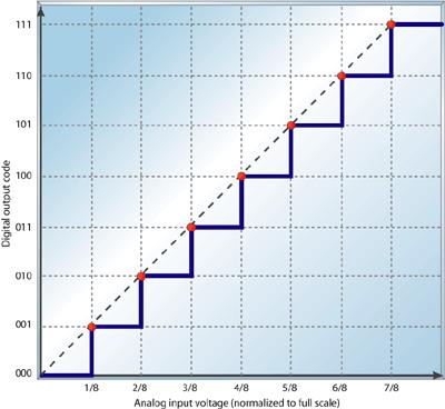
32 Integral nonlinearity The integral nonlinearity (INL) is the deviation of an ADC's transfer function from a straight line. This line is often a best-fit line among the points in the plot but can also be a line that connects the highest and lowest data points, or endpoints. INL is determined by measuring the voltage at which all code transitions occur and comparing them to the ideal. The difference between the ideal voltage levels at which code transitions occur and the actual voltage is the INL error, expressed in LSBs. INL error at any given point in an ADC's transfer function is the accumulation of all DNL errors of all previous (or lower) ADC codes, hence it's called integral nonlinearity.

33 Differential nonlinearity DNL is the worst cases variation of actual step size vs. ideal step size. It s a promise it won t be worse than X.

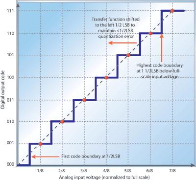
34 Sometimes the intentional ½ LSB shift is included here!

35 Full-scale error is also sometimes called gain error full-scale error is the difference between the ideal code transition to the highest output code and the actual transition to the output code when the offset error is zero.
36 Errors Once again: Errors in a specification are worst case. So if you have an INL of ±.25 LSB, you know that the device will never have more than.25 LSB error from its ideal value. That of course assumes you are operating within the specification Temperature, input voltage, input current available, etc. INL and DNL are the ones I expect you to work with Should know what full-scale error is
EECS 373 Design of Microprocessor-Based Systems
 EECS 373 Design of Microprocessor-Based Systems Ronald Dreslinski University of Michigan Sampling, ADCs, and DACs and more Some slides adapted from Mark Brehob, Prabal Dutta, Jonathan Hui & Steve Reinhardt
Advantages of Analog Representation. Varies continuously, like the property being measured. Represents continuous values. See Figure 12.
 Analog Signals Signals that vary continuously throughout a defined range. Representative of many physical quantities, such as temperature and velocity. Usually a voltage or current level. Digital Signals
Outline. Analog/Digital Conversion
 Analog/Digital Conversion The real world is analog. Interfacing a microprocessor-based system to real-world devices often requires conversion between the microprocessor s digital representation of values
EE 421L Digital Electronics Laboratory. Laboratory Exercise #9 ADC and DAC
 EE 421L Digital Electronics Laboratory Laboratory Exercise #9 ADC and DAC Department of Electrical and Computer Engineering University of Nevada, at Las Vegas Objective: The purpose of this laboratory
A-D and D-A Converters
 Chapter 5 A-D and D-A Converters (No mathematical derivations) 04 Hours 08 Marks When digital devices are to be interfaced with analog devices (or vice a versa), Digital to Analog converter and Analog
Analog to Digital Converters
 Analog to Digital Converters By: Byron Johns, Danny Carpenter Stephanie Pohl, Harry Bo Marr http://ume.gatech.edu/mechatronics_course/fadc_f05.ppt (unless otherwise marked) Presentation Outline Introduction:
PHYS225 Lecture 22. Electronic Circuits
 PHYS225 Lecture 22 Electronic Circuits Last lecture Digital to Analog Conversion DAC Converts digital signal to an analog signal Computer control of everything! Various types/techniques for conversion
ELG3336: Converters Analog to Digital Converters (ADCs) Digital to Analog Converters (DACs)
 Digital to Analog Converters (DACs)") ELG3336: Converters Analog to Digital Converters (ADCs) Digital to Analog Converters (DACs) Digital Output Dout 111 110 101 100 011 010 001 000 ΔV, V LSB V ref 8 V FSR 4 V 8 ref 7 V 8 ref Analog Input
ELG3336: Converters Analog to Digital Converters (ADCs) Digital to Analog Converters (DACs) Digital Output Dout 111 110 101 100 011 010 001 000 ΔV, V LSB V ref 8 V FSR 4 V 8 ref 7 V 8 ref Analog Input
The need for Data Converters
 The need for Data Converters ANALOG SIGNAL (Speech, Images, Sensors, Radar, etc.) PRE-PROCESSING (Filtering and analog to digital conversion) DIGITAL PROCESSOR (Microprocessor) POST-PROCESSING (Digital
Electronics A/D and D/A converters
 Electronics A/D and D/A converters Prof. Márta Rencz, Gábor Takács, Dr. György Bognár, Dr. Péter G. Szabó BME DED December 1, 2014 1 / 26 Introduction The world is analog, signal processing nowadays is
Analog to Digital Conversion
 Analog to Digital Conversion Why It s Needed Embedded systems often need to measure values of physical parameters These parameters are usually continuous (analog) and not in a digital form which computers
Lecture 6: Digital/Analog Techniques
 Lecture 6: Digital/Analog Techniques The electronics signals that we ve looked at so far have been analog that means the information is continuous. A voltage of 5.3V represents different information that
Fundamentals of Data Converters. DAVID KRESS Director of Technical Marketing
 Fundamentals of Data Converters DAVID KRESS Director of Technical Marketing 9/14/2016 Analog to Electronic Signal Processing Sensor (INPUT) Amp Converter Digital Processor Actuator (OUTPUT) Amp Converter
Based with permission on lectures by John Getty Laboratory Electronics II (PHSX262) Spring 2011 Lecture 9 Page 1
 Spring 2011 Lecture 9 Page 1") Today 3// Lecture 9 Analog Digital Conversion Sampled Data Acquisition Systems Discrete Sampling and Nyquist Digital to Analog Conversion Analog to Digital Conversion Homework Study for Exam next week
Today 3// Lecture 9 Analog Digital Conversion Sampled Data Acquisition Systems Discrete Sampling and Nyquist Digital to Analog Conversion Analog to Digital Conversion Homework Study for Exam next week
Analog I/O. ECE 153B Sensor & Peripheral Interface Design Winter 2016
 Analog I/O ECE 153B Sensor & Peripheral Interface Design Introduction Anytime we need to monitor or control analog signals with a digital system, we require analogto-digital (ADC) and digital-to-analog
System on a Chip. Prof. Dr. Michael Kraft
 System on a Chip Prof. Dr. Michael Kraft Lecture 5: Data Conversion ADC Background/Theory Examples Background Physical systems are typically analogue To apply digital signal processing, the analogue signal
EE251: Tuesday October 10
 EE251: Tuesday October 10 Analog to Digital Conversion Text Chapter 20 through section 20.2 TM4C Data Sheet Chapter 13 Lab #5 Writeup Lab Practical #1 this week Homework #4 is due on Thursday at 4:30 p.m.
UNIT III Data Acquisition & Microcontroller System. Mr. Manoj Rajale
 UNIT III Data Acquisition & Microcontroller System Mr. Manoj Rajale Syllabus Interfacing of Sensors / Actuators to DAQ system, Bit width, Sampling theorem, Sampling Frequency, Aliasing, Sample and hold
Assoc. Prof. Dr. Burak Kelleci
 DEPARTMENT OF ELECTRICAL &ELECTRONICS ENGINEERING ANALOG-TO-DIGITAL AND DIGITAL- TO-ANALOG CONVERTERS Assoc. Prof. Dr. Burak Kelleci Fall 2018 OUTLINE Nyquist-Rate DAC Thermometer-Code Converter Hybrid
Data Converters. Dr.Trushit Upadhyaya EC Department, CSPIT, CHARUSAT
 Data Converters Dr.Trushit Upadhyaya EC Department, CSPIT, CHARUSAT Purpose To convert digital values to analog voltages V OUT Digital Value Reference Voltage Digital Value DAC Analog Voltage Analog Quantity:
The simplest DAC can be constructed using a number of resistors with binary weighted values. X[3:0] is the 4-bit digital value to be converter to an
![The simplest DAC can be constructed using a number of resistors with binary weighted values. X[3:0] is the 4-bit digital value to be converter to an](/thumbs/73/68151962.jpg "The simplest DAC can be constructed using a number of resistors with binary weighted values. X[3:0] is the 4-bit digital value to be converter to an") 1 Although digital technology dominates modern electronic systems, the physical world remains mostly analogue in nature. The most important components that link the analogue world to digital systems are
1 Although digital technology dominates modern electronic systems, the physical world remains mostly analogue in nature. The most important components that link the analogue world to digital systems are
The counterpart to a DAC is the ADC, which is generally a more complicated circuit. One of the most popular ADC circuit is the successive
 1 The counterpart to a DAC is the ADC, which is generally a more complicated circuit. One of the most popular ADC circuit is the successive approximation converter. 2 3 The idea of sampling is fully covered
Analog-Digital Interface
 Analog-Digital Interface Tuesday 24 November 15 Summary Previous Class Dependability Today: Redundancy Error Correcting Codes Analog-Digital Interface Converters, Sensors / Actuators Sampling DSP Frequency
Analogue to Digital Conversion
 Analogue to Digital Conversion Turns electrical input (voltage/current) into numeric value Parameters and requirements Resolution the granularity of the digital values Integral NonLinearity proportionality
University of Pittsburgh
 University of Pittsburgh Experiment #7 Lab Report Analog-Digital Applications Submission Date: 08/01/2018 Instructors: Dr. Ahmed Dallal Shangqian Gao Submitted By: Nick Haver & Alex Williams Station #2
Working with ADCs, OAs and the MSP430
 Working with ADCs, OAs and the MSP430 Bonnie Baker HPA Senior Applications Engineer Texas Instruments 2006 Texas Instruments Inc, Slide 1 Agenda An Overview of the MSP430 Data Acquisition System SAR Converters
EEE312: Electrical measurement & instrumentation
 University of Turkish Aeronautical Association Faculty of Engineering EEE department EEE312: Electrical measurement & instrumentation Digital Electronic meters BY Ankara March 2017 1 Introduction The digital
Data Converters. Lecture Fall2013 Page 1
 Data Converters Lecture Fall2013 Page 1 Lecture Fall2013 Page 2 Representing Real Numbers Limited # of Bits Many physically-based values are best represented with realnumbers as opposed to a discrete number
Chapter 5: Signal conversion
 Chapter 5: Signal conversion Learning Objectives: At the end of this topic you will be able to: explain the need for signal conversion between analogue and digital form in communications and microprocessors
Analog-to-Digital i Converters
 CSE 577 Spring 2011 Analog-to-Digital i Converters Jaehyun Lim, Kyusun Choi Department t of Computer Science and Engineering i The Pennsylvania State University ADC Glossary DNL (differential nonlinearity)
UNIVERSITY OF CALIFORNIA College of Engineering Department of Electrical Engineering and Computer Sciences
 UNIVERSITY OF CALIFORNIA College of Engineering Department of Electrical Engineering and Computer Sciences Final Exam EECS 247 H. Khorramabadi Tues., Dec. 14, 2010 FALL 2010 Name: SID: Total number of
Linear Integrated Circuits
 Linear Integrated Circuits Single Slope ADC Comparator checks input voltage with integrated reference voltage, V REF At the same time the number of clock cycles is being counted. When the integrator output
ME 461 Laboratory #3 Analog-to-Digital Conversion
 ME 461 Laboratory #3 Analog-to-Digital Conversion Goals: 1. Learn how to configure and use the MSP430 s 10-bit SAR ADC. 2. Measure the output voltage of your home-made DAC and compare it to the expected
CHAPTER ELEVEN - Interfacing With the Analog World
 CHAPTER ELEVEN - Interfacing With the Analog World 11.1 (a) Analog output = (K) x (digital input) (b) Smallest change that can occur in the analog output as a result of a change in the digital input. (c)
Analogue to Digital Conversion
 Analogue to Digital Conversion Turns electrical input (voltage/current) into numeric value Parameters and requirements Resolution the granularity of the digital values Integral NonLinearity proportionality
Module 13: Interfacing ADC. Introduction ADC Programming DAC Programming Sensor Interfacing
 Module 13: Interfacing ADC Introduction ADC Programming DAC Programming Sensor Interfacing Introduction ADC Devices o Analog-to-digital converters (ADC) are among the most widely used devices for data
Chapter 2 Signal Conditioning, Propagation, and Conversion
 09/0 PHY 4330 Instrumentation I Chapter Signal Conditioning, Propagation, and Conversion. Amplification (Review of Op-amps) Reference: D. A. Bell, Operational Amplifiers Applications, Troubleshooting,
An 8-bit Analog-to-Digital Converter based on the Voltage-Dependent Switching Probability of a Magnetic Tunnel Junction
 An 8-bit Analog-to-Digital Converter based on the Voltage-Dependent Switching Probability of a Magnetic Tunnel Junction Won Ho Choi*, Yang Lv*, Hoonki Kim, Jian-Ping Wang, and Chris H. Kim *equal contribution
Lecture #6: Analog-to-Digital Converter
 Lecture #6: Analog-to-Digital Converter All electrical signals in the real world are analog, and their waveforms are continuous in time. Since most signal processing is done digitally in discrete time,
Analog ó Digital Conversion Sampled Data Acquisition Systems Discrete Sampling and Nyquist Digital to Analog Conversion Analog to Digital Conversion
 Today Analog ó Digital Conversion Sampled Data Acquisition Systems Discrete Sampling and Nyquist Digital to Analog Conversion Analog to Digital Conversion Analog Digital Analog Beneits o digital systems
Analogue Interfacing. What is a signal? Continuous vs. Discrete Time. Continuous time signals
 Analogue Interfacing What is a signal? Signal: Function of one or more independent variable(s) such as space or time Examples include images and speech Continuous vs. Discrete Time Continuous time signals
Introduction. These two operations are performed by data converters : Analogue-to-digital converter (ADC) Digital-to-analogue converter (DAC)
 Digital-to-analogue converter (DAC)") Lezione 7 Conversione analogico digitale Introduzione Campionamento di segnali analogici e Aliasing Porte di campionamento e di mantenimento Quantizzazione segnali analogici Ricostruzione del segnale analogico
Lezione 7 Conversione analogico digitale Introduzione Campionamento di segnali analogici e Aliasing Porte di campionamento e di mantenimento Quantizzazione segnali analogici Ricostruzione del segnale analogico
ELG4139: Converters Analog to Digital Converters (ADCs) Digital to Analog Converters (DACs)
 Digital to Analog Converters (DACs)") ELG4139: Converters Analog to Digital Converters (ADCs) Digital to Analog Converters (DACs) Digital Output Dout 111 110 101 100 011 010 001 000 ΔV, V LSB V ref 8 V FS 4 V 8 ref 7 V 8 ref Analog Input V
ELG4139: Converters Analog to Digital Converters (ADCs) Digital to Analog Converters (DACs) Digital Output Dout 111 110 101 100 011 010 001 000 ΔV, V LSB V ref 8 V FS 4 V 8 ref 7 V 8 ref Analog Input V
5. Transducers Definition and General Concept of Transducer Classification of Transducers
 5.1. Definition and General Concept of Definition The transducer is a device which converts one form of energy into another form. Examples: Mechanical transducer and Electrical transducer Electrical A
10. Chapter: A/D and D/A converter principles
 Punčochář, Mohylová: TELO, Chapter 10: A/D and D/A converter principles 1 10. Chapter: A/D and D/A converter principles Time of study: 6 hours Goals: the student should be able to define basic principles
Data Converter Fundamentals
 IsLab Analog Integrated Circuit Design Basic-25 Data Converter Fundamentals כ Kyungpook National University IsLab Analog Integrated Circuit Design Basic-1 A/D Converters in Signal Processing Signal Sources
Digital to Analog Converters (DAC) Adam Fleming Mark Hunkele 3/11/2005
 Adam Fleming Mark Hunkele 3/11/2005") Digital to Analog Converters (DAC) Adam Fleming Mark Hunkele 3/11/2005 Outline Purpose Types Performance Characteristics Applications 2 Purpose To convert digital values to analog voltages Performs inverse
Digital to Analog Converters (DAC) Adam Fleming Mark Hunkele 3/11/2005 Outline Purpose Types Performance Characteristics Applications 2 Purpose To convert digital values to analog voltages Performs inverse
Analogue-to-Digital Conversion
 Digital-to-Analogue to Conversion Analogue-to-Digital Conversion Module: EE2C2 Digital Design Lecturer: URL: http://www.personal.rdg.ac.uk/~stsgrimb/ email: j.b.grimbleby reading.ac.uk Number of Lectures:
Embedded Systems Lecture 2: Interfacing with the Environment. Björn Franke University of Edinburgh
 Embedded Systems Lecture 2: Interfacing with the Environment Björn Franke University of Edinburgh Overview Interfacing with the Physical Environment Signals, Discretisation Input (Sensors) Output (Actuators)
Analog to Digital Conversion
 Analog to Digital Conversion Florian Erdinger Lehrstuhl für Schaltungstechnik und Simulation Technische Informatik der Uni Heidelberg VLSI Design - Mixed Mode Simulation F. Erdinger, ZITI, Uni Heidelberg
Embedded Control. Week 3 (7/13/11)
") Embedded Control Week 3 (7/13/11) Week 3 15:00 Lecture Overview of analog signals Digital-to-analog conversion Analog-to-digital conversion 16:00 Lab NXT analog IO Overview of Analog Signals Continuous
Embedded Control Week 3 (7/13/11) Week 3 15:00 Lecture Overview of analog signals Digital-to-analog conversion Analog-to-digital conversion 16:00 Lab NXT analog IO Overview of Analog Signals Continuous
EE445L Spring 2018 Final EID: Page 1 of 7
 EE445L Spring 2018 Final EID: Page 1 of 7 Jonathan W. Valvano First: Last: This is the closed book section. Calculator is allowed (no laptops, phones, devices with wireless communication). You must put
INL PLOT REFIN DAC AMPLIFIER DAC REGISTER INPUT CONTROL LOGIC, REGISTERS AND LATCHES
 ICm ictm IC MICROSYSTEMS FEATURES 12-Bit 1.2v Low Power Single DAC With Serial Interface and Voltage Output DNL PLOT 12-Bit 1.2v Single DAC in 8 Lead TSSOP Package Ultra-Low Power Consumption Guaranteed
3. DAC Architectures and CMOS Circuits
 1/30 3. DAC Architectures and CMOS Circuits Francesc Serra Graells francesc.serra.graells@uab.cat Departament de Microelectrònica i Sistemes Electrònics Universitat Autònoma de Barcelona paco.serra@imb-cnm.csic.es
Cyber-Physical Systems ADC / DAC
 Cyber-Physical Systems ADC / DAC ICEN 553/453 Fall 2018 Prof. Dola Saha 1 Analog-to-Digital Converter (ADC) Ø ADC is important almost to all application fields Ø Converts a continuous-time voltage signal
ADC Resolution: Myth and Reality
 ADC Resolution: Myth and Reality Mitch Ferguson, Applications Engineering Manager Class ID: CC19I Renesas Electronics America Inc. Mr. Mitch Ferguson Applications Engineering Manager Specializes support
Environmental ADC Interface P Team Members
 Environmental ADC Interface P14346 Team Members Caleb Stephens- Electrical Engineer Kevin Oswald- Electrical Engineer Ory Maimon- Electrical Engineer Edward Wlodarczyk- Electrical Engineer Marissa Fox-
Lecture 9, ANIK. Data converters 1
 Lecture 9, ANIK Data converters 1 What did we do last time? Noise and distortion Understanding the simplest circuit noise Understanding some of the sources of distortion 502 of 530 What will we do today?
P a g e 1. Introduction
 P a g e 1 Introduction 1. Signals in digital form are more convenient than analog form for processing and control operation. 2. Real world signals originated from temperature, pressure, flow rate, force
Figure 1.1 Mechatronic system components (p. 3)
") Figure 1.1 Mechatronic system components (p. 3) Example 1.2 Measurement System Digital Thermometer (p. 5) Figure 2.2 Electric circuit terminology (p. 13) Table 2.2 Resistor color band codes (p. 18) Figure
Figure 1.1 Mechatronic system components (p. 3) Example 1.2 Measurement System Digital Thermometer (p. 5) Figure 2.2 Electric circuit terminology (p. 13) Table 2.2 Resistor color band codes (p. 18) Figure
8-Bit, high-speed, µp-compatible A/D converter with track/hold function ADC0820
 8-Bit, high-speed, µp-compatible A/D converter with DESCRIPTION By using a half-flash conversion technique, the 8-bit CMOS A/D offers a 1.5µs conversion time while dissipating a maximum 75mW of power.
Workshop ESSCIRC. Low-Power Data Acquisition System For Very Small Signals At Low Frequencies With12-Bit- SAR-ADC. 17. September 2010.
 Workshop ESSCIRC Low-Power Data Acquisition System For Very Small Signals At Low Frequencies With12-Bit- SAR-ADC 17. September 2010 Christof Dohmen Outline System Overview Analog-Front-End Chopper-Amplifier
EECS 373 Design of Microprocessor-Based Systems
 EECS 373 Design of Microprocessor-Based Systems Robert Dick University of Michigan Lecture 10: ADCs, DACs, and prototyping 11 October 2017 Some slides from Mark Brehob. 1 Review Serial buses UART Several
Sensors. Chapter 3. Storey: Electrical & Electronic Systems Pearson Education Limited 2004 OHT 3.1
 Sensors Chapter 3 Introduction Describing Sensor Performance Temperature Sensors Light Sensors Force Sensors Displacement Sensors Motion Sensors Sound Sensors Sensor Interfacing Storey: Electrical & Electronic
Tuesday, March 1st, 9:15 11:00. Snorre Aunet Nanoelectronics group Department of Informatics University of Oslo.
 Nyquist Analog to Digital it Converters Tuesday, March 1st, 9:15 11:00 Snorre Aunet (sa@ifi.uio.no) Nanoelectronics group Department of Informatics University of Oslo 3.1 Introduction 3.1.1 DAC applications
SPT BIT, 30 MSPS, TTL, A/D CONVERTER
 12-BIT, MSPS, TTL, A/D CONVERTER FEATURES Monolithic 12-Bit MSPS Converter 6 db SNR @ 3.58 MHz Input On-Chip Track/Hold Bipolar ±2.0 V Analog Input Low Power (1.1 W Typical) 5 pf Input Capacitance TTL
DATA CONVERSION AND LAB (17.368) Fall Class # 07. October 16, 2008
 Fall Class # 07. October 16, 2008") DATA CONVERSION AND LAB (17.368) Fall 2008 Class # 07 October 16, 2008 Dohn Bowden 1 Today s Lecture Outline Course Admin Lab #3 next week Exam in two weeks 10/30/08 Detailed Technical Discussions Digital
DATA CONVERSION AND LAB (17.368) Fall 2008 Class # 07 October 16, 2008 Dohn Bowden 1 Today s Lecture Outline Course Admin Lab #3 next week Exam in two weeks 10/30/08 Detailed Technical Discussions Digital
Data Acquisition & Computer Control
 Chapter 4 Data Acquisition & Computer Control Now that we have some tools to look at random data we need to understand the fundamental methods employed to acquire data and control experiments. The personal
ANALOG-TO-DIGITAL CONVERTERS
 ANALOG-TO-DIGITAL CONVERTERS Definition An analog-to-digital converter is a device which converts continuous signals to discrete digital numbers. Basics An analog-to-digital converter (abbreviated ADC,
ADC0808/ADC Bit µp Compatible A/D Converters with 8-Channel Multiplexer
 ADC0808/ADC0809 8-Bit µp Compatible A/D Converters with 8-Channel Multiplexer General Description The ADC0808, ADC0809 data acquisition component is a monolithic CMOS device with an 8-bit analog-to-digital
Page 1. Midterm #2. OpAmp Review. Inverting & Non-inverting Circuits CS/ECE 6780/5780. Al Davis. Almost ubiquitous analog circuit element since ~1968
 Midterm #2 Midterm 2 hints CS/ECE 6780/5780 Al Davis Today s topics: no practice midterm since it didn t help last time ADC s and DAC s chapter 11 of your text your kit has an A/D (Port D w/ DDR set to
12-Bit, Low-Power, Dual, Voltage-Output DAC with Serial Interface
 19-2124; Rev 2; 7/3 12-Bit, Low-Power, Dual, Voltage-Output General Description The dual,12-bit, low-power, buffered voltageoutput, digital-to-analog converter (DAC) is packaged in a space-saving 8-pin
MECE 3320 Measurements & Instrumentation. Data Acquisition
 MECE 3320 Measurements & Instrumentation Data Acquisition Dr. Isaac Choutapalli Department of Mechanical Engineering University of Texas Pan American Sampling Concepts 1 f s t Sampling Rate f s 2 f m or
Analog to Digital Conversion
 Analog to Digital Conversion 02534567998 6 4 2 3 4 5 6 ANALOG to DIGITAL CONVERSION Analog variation (Continuous, smooth variation) Digitized Variation (Discrete set of points) N2 N1 Digitization applied
DSP Project. Reminder: Project proposal is due Friday, October 19, 2012 by 5pm in my office (Small 239).
.") DSP Project eminder: Project proposal is due Friday, October 19, 2012 by 5pm in my office (Small 239). Budget: $150 for project. Free parts: Surplus parts from previous year s project are available on
DSP Project eminder: Project proposal is due Friday, October 19, 2012 by 5pm in my office (Small 239). Budget: $150 for project. Free parts: Surplus parts from previous year s project are available on
UNIT I Circuit Configuration for Linear ICs
 UNIT I Circuit Configuration for Linear ICs Current Mirror Circuit: A current mirror is a circuit designed to copy a current through one active device by controlling the current in another
Signal Characteristics and Conditioning
 Signal Characteristics and Conditioning Starting from the sensors, and working up into the system:. What characterizes the sensor signal types. Accuracy and Precision with respect to these signals 3. General
Fan in: The number of inputs of a logic gate can handle.
 Subject Code: 17333 Model Answer Page 1/ 29 Important Instructions to examiners: 1) The answers should be examined by key words and not as word-to-word as given in the model answer scheme. 2) The model
Interface Electronic Circuits
 Lecture (5) Interface Electronic Circuits Part: 1 Prof. Kasim M. Al-Aubidy Philadelphia University-Jordan AMSS-MSc Prof. Kasim Al-Aubidy 1 Interface Circuits: An interface circuit is a signal conditioning
UNITII. Other LICs and Data Converters
 UNITII Other LICs and Data Converters Other LICs and Data Converters: 555 timer Block diagram and features Astable Multivibrator Applications - Square wave oscillator, Ramp generator, Triangular waveform
Single-channel power supply monitor with remote temperature sense, Part 1
 Single-channel power supply monitor with remote temperature sense, Part 1 Nathan Enger, Senior Applications Engineer, Linear Technology Corporation - June 03, 2016 Introduction Many applications with a
1.8 V to 5 V Auto-Zero, In-Amp with Shutdown AD8563
 FEATURES Low offset voltage: μv max Low input offset drift: 0. μv/ C max High CMR: 0 db min @ G = 00 Low noise: 0. μv p-p from 0.0 Hz to 0 Hz Wide gain range: to 0,000 Single-supply operation:. V to. V
Microprocessors & Interfacing
 Lecture overview Microprocessors & Interfacing /Output output PMW Digital-to- (D/A) Conversion input -to-digital (A/D) Conversion Lecturer : Dr. Annie Guo S2, 2008 COMP9032 Week9 1 S2, 2008 COMP9032 Week9
Data Conversion and Lab (17.368) Fall Lecture Outline
 Fall Lecture Outline") Data Conversion and Lab (17.368) Fall 2013 Lecture Outline Class # 07 October 17, 2013 Dohn Bowden 1 Today s Lecture Outline Administrative Detailed Technical Discussions Digital to Analog Conversion Lab
Data Conversion and Lab (17.368) Fall 2013 Lecture Outline Class # 07 October 17, 2013 Dohn Bowden 1 Today s Lecture Outline Administrative Detailed Technical Discussions Digital to Analog Conversion Lab
Last Time. P and N type semiconductors Diode internals Transistors NPN PNP
 Last Time P and N type semiconductors Diode internals Transistors NPN PNP Device of the Day... Piezo microphone Device of the Day... Transistor Recap Transistors operate as current amplifiers With the
CMOS 12-Bit Serial Input Multiplying DIGITAL-TO-ANALOG CONVERTER
 CMOS 12-Bit Serial Input Multiplying DIGITAL-TO-ANALOG CONVERTER FEATURES 12-BICCURACY IN 8-PIN MINI-DIP AND 8-PIN SOIC FAST 3-WIRE SERIAL INTERFACE LOW INL AND DNL: ±1/2 LSB max GAIN ACCURACY TO ±1LSB
1.8 V to 5 V Auto-Zero, In-Amp with Shutdown AD8553
 .8 V to 5 V Auto-Zero, In-Amp with Shutdown FEATURES Low offset voltage: 20 μv max Low input offset drift: 0. μv/ C max High CMR: 20 db min @ G = 00 Low noise: 0.7 μv p-p from 0.0 Hz to 0 Hz Wide gain
Analog/Digital and Sampling
 Analog/Digital and Sampling Alexander Nelson October 22, 2018 University of Arkansas - Department of Computer Science and Computer Engineering Analog Signals in the real world are analog signals Process
ANALOG TO DIGITAL (ADC) and DIGITAL TO ANALOG CONVERTERS (DAC)
 and DIGITAL TO ANALOG CONVERTERS (DAC)") COURSE / CODE DIGITAL SYSTEM FUNDAMENTALS (ECE421) DIGITAL ELECTRONICS FUNDAMENTAL (ECE422) ANALOG TO DIGITAL (ADC) and DIGITAL TO ANALOG CONVERTERS (DAC) Connecting digital circuitry to sensor devices
COURSE / CODE DIGITAL SYSTEM FUNDAMENTALS (ECE421) DIGITAL ELECTRONICS FUNDAMENTAL (ECE422) ANALOG TO DIGITAL (ADC) and DIGITAL TO ANALOG CONVERTERS (DAC) Connecting digital circuitry to sensor devices
Chapter 2 Analog-to-Digital Conversion...
 Chapter... 5 This chapter examines general considerations for analog-to-digital converter (ADC) measurements. Discussed are the four basic ADC types, providing a general description of each while comparing
EE247 Lecture 20. Comparator architecture examples Flash ADC sources of error Sparkle code Meta-stability
 EE247 Lecture 2 ADC Converters ADC architectures (continued) Comparator architectures Latched comparators Latched comparators incorporating preamplifier Sample-data comparators Offset cancellation Comparator
Mixed-Signal-Electronics
 1 Mixed-Signal-Electronics PD Dr.-Ing. Stephan Henzler 2 Chapter 6 Nyquist Rate Analog-to-Digital Converters 3 Analog-to-Digital Converter Families Architecture Variant Speed Precision Counting Operation
CRN: MET-487 Instrumentation and Automatic Control June 28, 2010 August 5, 2010 Professor Paul Lin
 CRN: 32030 MET-487 Instrumentation and Automatic Control June 28, 2010 August 5, 2010 Professor Paul Lin Course Description: Class 2, Lab 2, Cr. 3, Junior class standing and 216 Instrumentation for pressure,
CHEMICAL ENGINEERING 2I03
 Student Name: Student ID: CHEMICAL ENGINEERING 2I03 DAY CLASS Duration 2 hours McMaster University Practice Exam Dr. M. Thompson The final test includes 60 questions on 12 pages. This test paper must be
ELG3336 Design of Mechatronics System
 ELG3336 Design of Mechatronics System Elements of a Data Acquisition System 2 Analog Signal Data Acquisition Hardware Your Signal Data Acquisition DAQ Device System Computer Cable Terminal Block Data Acquisition
High-Speed Analog to Digital Converters. ELCT 1003:High Speed ADCs
 High-Speed Analog to Digital Converters Ann Kotkat Barbara Georgy Mahmoud Tantawi Ayman Sakr Heidi El-Feky Nourane Gamal 1 Outline Introduction. Process of ADC. ADC Specifications. Flash ADC. Pipelined
+2.7V to +5.5V, Low-Power, Triple, Parallel 8-Bit DAC with Rail-to-Rail Voltage Outputs
 19-1560; Rev 1; 7/05 +2.7V to +5.5V, Low-Power, Triple, Parallel General Description The parallel-input, voltage-output, triple 8-bit digital-to-analog converter (DAC) operates from a single +2.7V to +5.5V
Lab 2: Discrete BJT Op-Amps (Part I)
") Lab 2: Discrete BJT Op-Amps (Part I) This is a three-week laboratory. You are required to write only one lab report for all parts of this experiment. 1.0. INTRODUCTION In this lab, we will introduce and
Lab 2: Discrete BJT Op-Amps (Part I) This is a three-week laboratory. You are required to write only one lab report for all parts of this experiment. 1.0. INTRODUCTION In this lab, we will introduce and
SCLK 4 CS 1. Maxim Integrated Products 1
 19-172; Rev ; 4/ Dual, 8-Bit, Voltage-Output General Description The contains two 8-bit, buffered, voltage-output digital-to-analog converters (DAC A and DAC B) in a small 8-pin SOT23 package. Both DAC
Using Optical Isolation Amplifiers in Power Inverters for Voltage, Current and Temperature Sensing
 Using Optical Isolation Amplifiers in Power Inverters for Voltage, Current and Temperature Sensing by Hong Lei Chen, Product Manager, Avago Technologies Abstract Many industrial equipments and home appliances