Figure 1.1 Mechatronic system components (p. 3)
|
|
|
- Tamsin Tyler
- 5 years ago
- Views:
Transcription
1 Figure 1.1 Mechatronic system components (p. 3) Example 1.2 Measurement System Digital Thermometer (p. 5)
2 Figure 2.2 Electric circuit terminology (p. 13)

3 Table 2.2 Resistor color band codes (p. 18)
4 Figure 2.13 Kirchhoff s voltage law (p. 22)
5 Example 2.4 Circuit Analysis (p. 29)
6 Figure 2.18 Real voltage source with output impedance (p. 31) Figure 2.21 Real ammeter with input impedance (p. 32) Figure 2.22 Real voltmeter with input impedance (p. 32)
7 Figure 2.28 Sinusoidal waveform (p. 37) Figure 2.29 Sinusoidal signal DC offset (p. 38)
8 Figure 2.30 Phasor representation of a sinusoidal signal (p. 40)
9 Example 2.7 AC Circuit Analysis (p. 42)

10 Figure 3.2 pn Junction characteristics (p. 78) Figure 3.3 Silicon diode (p. 79)
11 Figure 3.6 Ideal, actual, and approximate diode curves (p. 80)
12 Figure 3.9 Inductive load flyback protection (p. 83) Figure 3.10 Flyback action (p. 84)
13 Figure 3.11 Light-emitting diode (p. 86) Figure 3.13 Typical LED circuit in digital systems (p. 86)
14 Figure 3.19 npn Bipolar junction transistor (p. 96) Example 3.4 Guaranteeing a Transistor Is in Saturation (p. 99)
15 Figure 6.1 Analog and digital signals (p. 206)
16 Table 6.3 Combinational logic operations (p. 211)
17 Figure 6.25 QUAD NAND gate IC pin-out (p. 238)

18
19 Figure 6.4 AND realization schematic of the security system. (p. 219)

20 Sum Of Products (SOP) Product of Sums (POS) EXAMPLE 6.4 Example 6.4 Sum of Products and Product of Sums (p. 220)
 Table 6.")
21 Figure 6.5 Clock pulse edges (p. 222) Figure 6.6 RS flip-flop (p. 223) Table 6.4 Truth table for the RS flip-flop (p. 223)
22 Figure 6.7 RS flip-flop internal design and timing (p. 224)

23 Table 6.5 Positive-edge-triggered RS flip-flop truth table (p. 225)
24 Figure 6.16 Switch bounce (p. 230) Figure 6.17 Switch debouncer circuit (p. 223)
25 Figure bit data register (p. 232) Figure bit binary counter (p. 232)
26 Figure 6.34 Seven-segment LED display (p. 245) Figure 6.33 Cascaded decade counters (p. 244)
27 Figure 6.42 Block diagram of the 555 IC (p. 248) Figure 6.43 One-shot timing (p. 250)
28 Figure 7.2 Components of a typical full-featured microcontroller (p. 271)
29 Figure 7.4 PIC16F84 pin-out and required external components (p. 274)

 4 PicBasic Pro logical")
30 Table 7.3 Selected PicBasic Pro math operators and functions (p. 285) Table 7.4 PicBasic Pro logical comparison operators (p. 287)
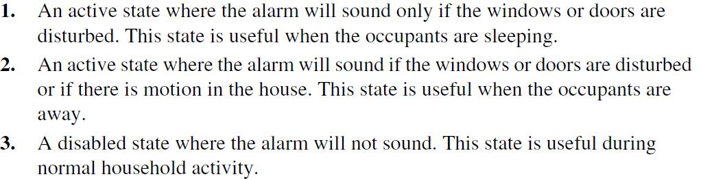
31 Example 7.5 PicBasic Pro Program for the Home Security System Example (p. 286)
32 Figure 7.19 Interface circuits for input devices (p. 329)
33 Figure 7.20 Interface circuits for output devices (p. 330)
34 Figure 4.2 Amplitude linearity and nonlinearity (p. 125)
35 Section 4.3 FOURIER SERIES REPRESENTATION OF SIGNALS (pg. 126)
36 Figure 4.4 Harmonic decomposition of a square wave (p. 128) Figure 4.5 Spectrum of a square wave (p. 129)
37 Figure 4.6 Frequency response and bandwidth (p. 130)
38 Figure 4.7 Effect of measurement system bandwidth on signal spectrum (p. 132)
39 Example 4.1 Bandwidth of an Electrical Network (p. 133)
40 Figure 4.8 Relationship between phase and time displacement (p. 135)
41 Figure 4.11 Displacement potentiometer (p. 138)
42 Figure 4.12 First-order response (p. 141)
43 Figure 4.15 Strip chart recorder as an example of a second-order system (p. 144)
44 Figure 4.17 Second-order step responses (p. 148)
45
46
47 Figure 4.19 Second-order system amplitude response (p. 151)
48 Figure 4.20 Second-order system phase response (p. 152)
49 Figure 4.21 Example of system analogies (p. 158)
50 Figure 4.22 Mechanical system analogy example (p. 159)
51 Figure 5.2 Op amp terminology and schematic representation (p. 171)
52 Figure 5.4 Op amp equivalent circuit (p. 172)
53 Figure op amp pin-out (p. 173)
54 R F iout Vin + iin R C Vout Vout ideal model Figure 5.8 Equivalent circuit for an inverting amplifier (p. 175)
55
56 Figure 5.11 Equivalent circuit for a noninverting amplifier (p. 177)
57 Figure 5.19 Ideal integrator (p. 185)
58 Figure 5.20 Improved integrator (p. 186)
59 Figure 5.26 Typical op amp open- and closed-loop response (p. 191)
60 Example 5.1 Sizing Resistors in Op Amp Circuits (p. 195)
61 Figure 8.1 Analog signal and sampled equivalent (p. 377)
62 Figure 8.2 Aliasing (p. 378)

63 Example 8.1 Sampling Theorem and Aliasing (p. 379)
64 Figure 8.7 Analog-to-digital conversion (p. 384)
65 Figure 8.11 A/D flash converter (p. 390)
 Figure 2.50 Ground loop (p.")
66 Figure 2.49 Inductive coupling (p. 62) Figure 2.50 Ground loop (p. 63)
67 Figure 9.2 Switches (p. 412)
68 Figure 9.4 Potentiometer (p. 413)
69 Figure 9.6 Linear variable differential transformer (p. 415) Figure 9.8 LVDT linear range (p. 415)
70 Figure 9.9 LVDT demodulation (p. 415)
71 Figure bit gray code absolute encoder disk track patterns (p. 419)
72 Figure bit natural binary absolute encoder disk track patterns (p. 419)
73 Table bit gray and natural binary codes (p. 420)
74 Figure 9.13 Gray-code-to-binary-code conversion (p. 420)
75 Figure 9.14 Incremental encoder disk track patterns (p. 421)
76 Figure 9.15 Quadrature direction sensing and resolution enhancement (p. 422)
77 Figure X quadrature decoder circuit (p. 423)
 Figure 10.3 Voice coil (p.")
78 Figure 10.2 Solenoids (p. 468) Figure 10.3 Voice coil (p. 468)
79 Figure 10.6 Motor construction and terminology (p. 470)

80 Figure Electric motor field-field interaction (p. 474)
81 Figure 10.8 Electric motor field-current interaction (p. 472)
82 Figure Stepper motor step sequence (p. 490)
83 Figure Example of a unipolar stepper motor (p. 492)
 Table 10.2 Unipolar half-step phase sequence (p.")
84 Table 10.1 Unipolar full-step phase sequence (p. 493) Table 10.2 Unipolar half-step phase sequence (p. 493)
85 Figure Unipolar stepper motor full-step drive circuit (p. 496)

86 Figure 9.17 Metal foil strain gage construction (p. 426)
87 Figure 9.18 Rectangular conductor (p. 427)
88 Figure 9.20 Dynamic unbalanced bridge circuit (p. 431)
89 Figure 9.21 Leadwire effects in 1/4 bridge circuits (p. 433) Figure 9.23 Temperature compensation with a dummy gage in a half bridge circuit (p. 433)
90 Figure 9.26 General state of planar stress on the surface of a component (p. 436)
91 Figure 9.29 Rectangular strain gage rosette (p. 437)
92 Figure 9.44 Accelerometer displacement references and free-body diagram (p. 451)
93 Accelerometer Frequency Response Analysis
94 Figure 9.45 Ideal accelerometer amplitude response (p. 453)
95 Figure 9.48 Ideal accelerometer phase response (p. 454)

96 Figure 9.48 Piezoelectric accelerometer construction (p. 456)
97 Figure 9.51 Piezoelectric accelerometer frequency response (p. 458)
98 Figure 9.34 Thermocouple circuit (p. 443) Figure 9.35 Law of leadwire temperatures (p. 444) Figure 9.36 Law of intermediate leadwire metals (p. 444)
99 Figure 9.37 Law of intermediate junction metals (p. 445) Figure 9.38 Law of intermediate temperatures (p. 445) Figure 9.39 Law of intermediate metals (p. 446)
100 Comprehensive Case Study Truth Table D C B A h g f e d c b a
CRN: MET-487 Instrumentation and Automatic Control June 28, 2010 August 5, 2010 Professor Paul Lin
 CRN: 32030 MET-487 Instrumentation and Automatic Control June 28, 2010 August 5, 2010 Professor Paul Lin Course Description: Class 2, Lab 2, Cr. 3, Junior class standing and 216 Instrumentation for pressure,
Chapter 8. Chapter 9. Chapter 6. Chapter 10. Chapter 11. Chapter 7
 5.5 Series and Parallel Combinations of 246 Complex Impedances 5.6 Steady-State AC Node-Voltage 247 Analysis 5.7 AC Power Calculations 256 5.8 Using Power Triangles 258 5.9 Power-Factor Correction 261
Mechatronics 421/780. Department of Mechanical and Aeronautical Engineering. Page 1 of 10
 Mechatronics 421/780 Department of Mechanical and Aeronautical Engineering Page 1 of 10 OVERVIEW AND OBJECTIVES 1. Course Overview Mechatronics (MEG 421 or MEG 780) is a multidisciplinary field of engineering
Preface... iii. Chapter 1: Diodes and Circuits... 1
 Table of Contents Preface... iii Chapter 1: Diodes and Circuits... 1 1.1 Introduction... 1 1.2 Structure of an Atom... 2 1.3 Classification of Solid Materials on the Basis of Conductivity... 2 1.4 Atomic
ELECTRONICS WITH DISCRETE COMPONENTS
 ELECTRONICS WITH DISCRETE COMPONENTS Enrique J. Galvez Department of Physics and Astronomy Colgate University WILEY John Wiley & Sons, Inc. ^ CONTENTS Preface vii 1 The Basics 1 1.1 Foreword: Welcome to
R & D Electronics DIGITAL IC TRAINER. Model : DE-150. Feature: Object: Specification:
 DIGITAL IC TRAINER Model : DE-150 Object: To Study the Operation of Digital Logic ICs TTL and CMOS. To Study the All Gates, Flip-Flops, Counters etc. To Study the both the basic and advance digital electronics
ELECTRONICS ADVANCED SUPPLEMENTARY LEVEL
 ELECTRONICS ADVANCED SUPPLEMENTARY LEVEL AIMS The general aims of the subject are : 1. to foster an interest in and an enjoyment of electronics as a practical and intellectual discipline; 2. to develop
PESIT BANGALORE SOUTH CAMPUS BASIC ELECTRONICS
 PESIT BANGALORE SOUTH CAMPUS QUESTION BANK BASIC ELECTRONICS Sub Code: 17ELN15 / 17ELN25 IA Marks: 20 Hrs/ Week: 04 Exam Marks: 80 Total Hours: 50 Exam Hours: 03 Name of Faculty: Mr. Udoshi Basavaraj Module
Contents. Acknowledgments. About the Author
 Contents Figures Tables Preface xi vii xiii Acknowledgments About the Author xv xvii Chapter 1. Basic Mathematics 1 Addition 1 Subtraction 2 Multiplication 2 Division 3 Exponents 3 Equations 5 Subscripts
Introductory Electronics for Scientists and Engineers
 Introductory Electronics for Scientists and Engineers Second Edition ROBERT E. SIMPSON University of New Hampshire Allyn and Bacon, Inc. Boston London Sydney Toronto Contents Preface xiü 1 Direct Current
Basic Operational Amplifier Circuits
 Basic Operational Amplifier Circuits Comparators A comparator is a specialized nonlinear op-amp circuit that compares two input voltages and produces an output state that indicates which one is greater.
M.D. Singh J.G. Joshi MECHATRONICS
 M.D. Singh J.G. Joshi MECHATRONICS MECHATRONICS MECHATRONICS M.D. SINGH Formerly Principal Sagar Institute of Technology and Research Bhopal J.G. JOSHI Lecturer Department of Electronics and Telecommunication
DC/AC CIRCUITS: CONVENTIONAL FLOW TEXTBOOKS
 4 PEARSON CUSTOM ELECTRONICS TECHNOLOGY DC/AC CIRCUITS: CONVENTIONAL FLOW TEXTBOOKS AVAILABLE MARCH 2009 Boylestad Introductory Circuit Analysis, 11/e, 0-13-173044-4 Introduction 32 LC4501 Voltage and
Analytical Chemistry II
 Analytical Chemistry II L3: Signal processing (selected slides) Semiconductor devices Apart from resistors and capacitors, electronic circuits often contain nonlinear devices: transistors and diodes. The
Calhoon MEBA Engineering School. Study Guide for Proficiency Testing Industrial Electronics
 Calhoon MEBA Engineering School Study Guide for Proficiency Testing Industrial Electronics January 0. Which factors affect the end-to-end resistance of a metallic conductor?. A waveform shows three complete
Microelectronic Circuits
 SECOND EDITION ISHBWHBI \ ' -' Microelectronic Circuits Adel S. Sedra University of Toronto Kenneth С Smith University of Toronto HOLT, RINEHART AND WINSTON HOLT, RINEHART AND WINSTON, INC. New York Chicago
multivibrator; Introduction to silicon-controlled rectifiers (SCRs).
.") Appendix The experiments of which details are given in this book are based largely on a set of 'modules' specially designed by Dr. K.J. Close. These 'modules' are now made and marketed by Irwin-Desman
Appendix The experiments of which details are given in this book are based largely on a set of 'modules' specially designed by Dr. K.J. Close. These 'modules' are now made and marketed by Irwin-Desman
GCSE Electronics. Scheme of Work
 GCSE Electronics Scheme of Work Week Topic Detail Notes 1 Practical skills assemble a circuit using a diagram recognize a component from its physical appearance (This is a confidence building/motivating
Electronic Circuits EE359A
 Electronic Circuits EE359A Bruce McNair B206 bmcnair@stevens.edu 201-216-5549 1 Memory and Advanced Digital Circuits - 2 Chapter 11 2 Figure 11.1 (a) Basic latch. (b) The latch with the feedback loop opened.
V-LAB COMPUTER INTERFACED TRAINING SET
 is an important tool for Vocational Education with it s built-in measurement units and signal generators that are interfaced with computer for control and measurement. is a device for real-time measurement
EE : ELECTRICAL ENGINEERING Module 8 : Analog and Digital Electronics INDEX
 Pearl Centre, S.B. Marg, Dadar (W), Mumbai 400 028. Tel. 4232 4232 EE : ELECTRICAL ENGINEERING Module 8 : Analog and Digital Electronics Contents INDEX Sub Topics 1. Characteristics of Diodes, BJT & FET
WINTER 14 EXAMINATION
 Subject Code:173 WINTER 14 EXAMINATION Model Answer Important Instructions to examiners: 1) The answers should be examined by key words and not as word-to-word as given in the model answer scheme. 2) The
PRODUCT CATALOG TRAINER KITS FOR ENGINEERING DEGREE COURSES MICROTECH INDUSTRIES
 PRODUCT CATALOG TRAINER KITS FOR ENGINEERING DEGREE COURSES µ MICROTECH INDUSTRIES 14A/ 1G, ULTADANGA ROAD GOPAL BHAVAN KOLKATA 700 004 Phone : (033) 3296 9273, Cell : 98312 63293 E- mail : hkg@cal3.vsnl.net.in
IT.MLD900 SENSORS AND TRANSDUCERS TRAINER. Signal Conditioning
 SENSORS AND TRANSDUCERS TRAINER IT.MLD900 The s and Instrumentation Trainer introduces students to input sensors, output actuators, signal conditioning circuits, and display devices through a wide range
Basic Electronics SYLLABUS BASIC ELECTRONICS. Subject Code : 15ELN15/25 IA Marks : 20. Hrs/Week : 04 Exam Hrs. : 03. Total Hrs. : 50 Exam Marks : 80
 SYLLABUS BASIC ELECTRONICS Subject Code : /25 IA Marks : 20 Hrs/Week : 04 Exam Hrs. : 03 Total Hrs. : 50 Exam Marks : 80 Course objectives: The course objective is to make students of all the branches
1. An engineer measures the (step response) rise time of an amplifier as. Estimate the 3-dB bandwidth of the amplifier. (2 points)
 rise time of an amplifier as. Estimate the 3-dB bandwidth of the amplifier. (2 points)") Exam 1 Name: Score /60 Question 1 Short Takes 1 point each unless noted otherwise. 1. An engineer measures the (step response) rise time of an amplifier as. Estimate the 3-dB bandwidth of the amplifier.
Exam 1 Name: Score /60 Question 1 Short Takes 1 point each unless noted otherwise. 1. An engineer measures the (step response) rise time of an amplifier as. Estimate the 3-dB bandwidth of the amplifier.
C H A P T E R 02. Operational Amplifiers
 C H A P T E R 02 Operational Amplifiers The Op-amp Figure 2.1 Circuit symbol for the op amp. Figure 2.2 The op amp shown connected to dc power supplies. The Ideal Op-amp 1. Infinite input impedance 2.
ENGINEERING. Unit 4 Principles of electrical and electronic engineering Suite. Cambridge TECHNICALS LEVEL 3
 2016 Suite Cambridge TECHNICALS LEVEL 3 ENGINEERING Unit 4 Principles of electrical and electronic engineering D/506/7269 Guided learning hours: 60 Version 3 October 2017 - black lines mark updates ocr.org.uk/engineering
DARSHAN INSTITUTE OF ENGINEERING & TECHNOLOGY
 BASIC ELECTRONICS (2006) Assignment:-: Circuit Concept. Explain in brief about Lumped circuit elements called resistor and capacitor. 2. How does a voltmeter differ from an ammeter? 3. State kirchhoff's
UNIT-1: CIRCUIT CONCEPT. capacitor. the market to purchase a resistor, apart from resistance what else will you quote so that the safety is ensured?
 UNIT-1: CIRCUIT CONCEPT * 1) Explain in brief about Lumped circuit elements called resistor and capacitor. ** 2) Write a short note on Ammeter and Voltmeter. ** 3) How does a voltmeter differ from an ammeter?
Entry Level Assessment Blueprint Electronics Technology
 Blueprint Test Code: 4135 / Version: 01 Specific Competencies and Skills Tested in this Assessment: Safety Practices Demonstrate safe working procedures Explain the purpose of OSHA and how it promotes
Electronic Components And Circuit Analysis
 Theory /Practical Theory Semester /Annual Semester Semester No. I II Swami Ramanand Teerth Marathwada University, Nanded Syllabus B. Sc. First Year ELECTRONICS Semester System (MCQ Pattern) (To Be Implemented
ELECTRONIC CIRCUITS. Time: Three Hours Maximum Marks: 100
 EC 40 MODEL TEST PAPER - 1 ELECTRONIC CIRCUITS Time: Three Hours Maximum Marks: 100 Answer five questions, taking ANY TWO from Group A, any two from Group B and all from Group C. All parts of a question
Additional Programs for the Electronics Module Part No
 Additional Programs for the Electronics Module Part No. 5263 Contents:. Additional programs for the Electronics Module....2 Wiring of the inputs and outputs... 2.3 Additional programs for digital technology...
hij Teacher Resource Bank GCE Electronics Exemplar Examination Questions ELEC2 Further Electronics
 hij Teacher Resource Bank GCE Electronics Exemplar Examination Questions ELEC2 Further Electronics The Assessment and Qualifications Alliance (AQA) is a company limited by guarantee registered in England
Digital Electronics Course Objectives
 Digital Electronics Course Objectives In this course, we learning is reported using Standards Referenced Reporting (SRR). SRR seeks to provide students with grades that are consistent, are accurate, and
Veer Narmad South Gujarat University, Surat
 Unit I: Passive circuit elements (With effect from June 2017) Syllabus for: F Y B Sc (Electronics) Semester- 1 PAPER I: Basic Electrical Circuits Resistors, resistor types, power ratings, resistor colour
Department of Electronics & Communication Engineering LAB MANUAL SUBJECT: DIGITAL COMMUNICATION LABORATORY [ECE324] (Branch: ECE)
![Department of Electronics & Communication Engineering LAB MANUAL SUBJECT: DIGITAL COMMUNICATION LABORATORY [ECE324] (Branch: ECE)](/thumbs/96/127341232.jpg "Department of Electronics & Communication Engineering LAB MANUAL SUBJECT: DIGITAL COMMUNICATION LABORATORY [ECE324] (Branch: ECE)") Department of Electronics & Communication Engineering LAB MANUAL SUBJECT: DIGITAL COMMUNICATION LABORATORY [ECE324] B.Tech Year 3 rd, Semester - 5 th (Branch: ECE) Version: 01 st August 2018 The LNM Institute
Department of Electronics & Communication Engineering LAB MANUAL SUBJECT: DIGITAL COMMUNICATION LABORATORY [ECE324] B.Tech Year 3 rd, Semester - 5 th (Branch: ECE) Version: 01 st August 2018 The LNM Institute
GOVERNMENT OF KARNATAKA KARNATAKA STATE PRE-UNIVERSITY EDUCATION EXAMINATION BOARD II YEAR PUC EXAMINATION MARCH-2013 SCHEME OF VALUATION
 GOVERNMENT OF KARNATAKA KARNATAKA STATE PRE-UNIVERSITY EDUCATION EXAMINATION BOARD II YEAR PUC EXAMINATION MARCH-03 SCHEME OF VALUATION Subject Code: 0 Subject: PART - A 0. What does the arrow mark indicate
R.B.V.R.R. WOMEN S COLLEGE (AUTONOMOUS) Narayanaguda, Hyderabad. ELECTRONIC PRINCIPLES AND APPLICATIONS
 Narayanaguda, Hyderabad. ELECTRONIC PRINCIPLES AND APPLICATIONS") R.B.V.R.R. WOMEN S COLLEGE (AUTONOMOUS) Narayanaguda, Hyderabad. DEPARTMENT OF PHYSICS QUESTION BANK FOR SEMESTER V PHYSICS PAPER VI (A) ELECTRONIC PRINCIPLES AND APPLICATIONS UNIT I: SEMICONDUCTOR DEVICES
R.B.V.R.R. WOMEN S COLLEGE (AUTONOMOUS) Narayanaguda, Hyderabad. DEPARTMENT OF PHYSICS QUESTION BANK FOR SEMESTER V PHYSICS PAPER VI (A) ELECTRONIC PRINCIPLES AND APPLICATIONS UNIT I: SEMICONDUCTOR DEVICES
Paper No. Name of the Paper Theory marks Practical marks Periods per week Semester-I I Semiconductor
 Swami Ramanand Teerth Marathwada University, Nanded B. Sc. First Year Electronics Syllabus Semester system (To be implemented from Academic Year 2009-10) Name of the Theory marks Practical marks Periods
1 Signals and systems, A. V. Oppenhaim, A. S. Willsky, Prentice Hall, 2 nd edition, FUNDAMENTALS. Electrical Engineering. 2.
 1 Signals and systems, A. V. Oppenhaim, A. S. Willsky, Prentice Hall, 2 nd edition, 1996. FUNDAMENTALS Electrical Engineering 2.Processing - Analog data An analog signal is a signal that varies continuously.
Operational Amplifier (Op-Amp)
") Operational Amplifier (Op-Amp) 1 Contents Op-Amp Characteristics Op-Amp Circuits - Noninverting Amplifier - Inverting Amplifier - Comparator - Differential - Summing - Integrator - Differentiator 2 Introduction
Operational Amplifier (Op-Amp) 1 Contents Op-Amp Characteristics Op-Amp Circuits - Noninverting Amplifier - Inverting Amplifier - Comparator - Differential - Summing - Integrator - Differentiator 2 Introduction
PHYS225 Lecture 18. Electronic Circuits
 PHYS225 Lecture 18 Electronic Circuits Oscillators and Timers Oscillators & Timers Produce timing signals to initiate measurement Periodic or single pulse Periodic output at known (controlled) frequency
4.2.2 Metal Oxide Semiconductor Field Effect Transistor (MOSFET)
") 4.2.2 Metal Oxide Semiconductor Field Effect Transistor (MOSFET) The Metal Oxide Semitonductor Field Effect Transistor (MOSFET) has two modes of operation, the depletion mode, and the enhancement mode.
4.2.2 Metal Oxide Semiconductor Field Effect Transistor (MOSFET) The Metal Oxide Semitonductor Field Effect Transistor (MOSFET) has two modes of operation, the depletion mode, and the enhancement mode.
Associate In Applied Science In Electronics Engineering Technology Expiration Date:
 PROGRESS RECORD Study your lessons in the order listed below. Associate In Applied Science In Electronics Engineering Technology Expiration Date: 1 2330A Current and Voltage 2 2330B Controlling Current
using dc inputs. You will verify circuit operation with a multimeter.
 Op Amp Fundamentals using dc inputs. You will verify circuit operation with a multimeter. FACET by Lab-Volt 77 Op Amp Fundamentals O circuit common. a. inverts the input voltage polarity. b. does not invert
Number of Lessons:155 #14B (P) Electronics Technology with Digital and Microprocessor Laboratory Completion Time: 42 months
 Electronics Technology with Digital and Microprocessor Laboratory Completion Time: 42 months") PROGRESS RECORD Study your lessons in the order listed below. Number of Lessons:155 #14B (P) Electronics Technology with Digital and Microprocessor Laboratory Completion Time: 42 months 1 2330A Current
PROGRESS RECORD Study your lessons in the order listed below. Number of Lessons:155 #14B (P) Electronics Technology with Digital and Microprocessor Laboratory Completion Time: 42 months 1 2330A Current
Electrical, Electronic and Communications Engineering Technology/Technician CIP Task Grid
 Secondary Task List 100 SAFETY 101 Describe OSHA safety regulations. 102 Identify, select, and demonstrate proper hand tool use for electronics work. 103 Recognize the types and usages of fire extinguishers.
Index. n A. n B. n C. Base biasing transistor driver circuit, BCD-to-Decode IC, 44 46
 Index n A Android Droid X smartphone, 165 Arduino-based LCD controller with an improved event trigger, 182 with auto-adjust contrast control, 181 block diagram, 189, 190 circuit diagram, 187, 189 delay()
DIGITAL ELECTRONICS. Methods & diagrams : 1 Graph plotting : - Tables & analysis : - Questions & discussion : 6 Performance : 3
 DIGITAL ELECTRONICS Marking scheme : Methods & diagrams : 1 Graph plotting : - Tables & analysis : - Questions & discussion : 6 Performance : 3 Aim: This experiment will investigate the function of the
Differential Amplifier : input. resistance. Differential amplifiers are widely used in engineering instrumentation
 Differential Amplifier : input resistance Differential amplifiers are widely used in engineering instrumentation Differential Amplifier : input resistance v 2 v 1 ir 1 ir 1 2iR 1 R in v 2 i v 1 2R 1 Differential
B.E. SEMESTER III (ELECTRICAL) SUBJECT CODE: X30902 Subject Name: Analog & Digital Electronics
 SUBJECT CODE: X30902 Subject Name: Analog & Digital Electronics") B.E. SEMESTER III (ELECTRICAL) SUBJECT CODE: X30902 Subject Name: Analog & Digital Electronics Sr. No. Date TITLE To From Marks Sign 1 To verify the application of op-amp as an Inverting Amplifier 2 To
B.E. SEMESTER III (ELECTRICAL) SUBJECT CODE: X30902 Subject Name: Analog & Digital Electronics Sr. No. Date TITLE To From Marks Sign 1 To verify the application of op-amp as an Inverting Amplifier 2 To
GOVERNMENT OF KARNATAKA KARNATAKA STATE PRE-UNIVERSITY EDUCATION EXAMINATION BOARD II YEAR PUC EXAMINATION JULY-2012 SCHEME OF VALUATION
 GOVERNMENT OF KARNATAKA KARNATAKA STATE PRE-UNIVERSITY EDUCATION EXAMINATION BOARD II YEAR PUC EXAMINATION JULY-0 SCHEME OF VALUATION Subject Code: 40 Subject: PART - A 0. Which region of the transistor
UPSC Electrical Engineering Syllabus
 UPSC Electrical Engineering Syllabus UPSC Electrical Engineering Syllabus PAPER I 1. Circuit Theory: Circuit components; network graphs; KCL, KVL; circuit analysis methods: nodal analysis, mesh analysis;
Revised April Unit/Standard Number. Proficiency Level Achieved: (X) Indicates Competency Achieved to Industry Proficiency Level
 Indicates Competency Achieved to Industry Proficiency Level") Unit/Standard Number Electrical, Electronic and Communications Engineering Technology/Technician CIP 15.0303 Task Grid Secondary Competency Task List 100 SAFETY 101 Demonstrate an understanding of state,
Unit/Standard Number Electrical, Electronic and Communications Engineering Technology/Technician CIP 15.0303 Task Grid Secondary Competency Task List 100 SAFETY 101 Demonstrate an understanding of state,
EE283 Electrical Measurement Laboratory Laboratory Exercise #7: Digital Counter
 EE283 Electrical Measurement Laboratory Laboratory Exercise #7: al Counter Objectives: 1. To familiarize students with sequential digital circuits. 2. To show how digital devices can be used for measurement
USER MANUAL FOR THE LM2901 QUAD VOLTAGE COMPARATOR FUNCTIONAL MODULE
 USER MANUAL FOR THE LM2901 QUAD VOLTAGE COMPARATOR FUNCTIONAL MODULE LM2901 Quad Voltage Comparator 1 5/18/04 TABLE OF CONTENTS 1. Index of Figures....3 2. Index of Tables. 3 3. Introduction.. 4-5 4. Theory
BINARY AMPLITUDE SHIFT KEYING
 BINARY AMPLITUDE SHIFT KEYING AIM: To set up a circuit to generate Binary Amplitude Shift keying and to plot the output waveforms. COMPONENTS AND EQUIPMENTS REQUIRED: IC CD4016, IC 7474, Resistors, Zener
IFB270 Advanced Electronic Circuits
 IFB270 Advanced Electronic Circuits Chapter 13: Basic op-amp circuits Prof. Manar Mohaisen Department of EEC Engineering Introduction Review of the Precedent Lecture Op-amp operation modes and parameters
ni.com Sensor Measurement Fundamentals Series
 Sensor Measurement Fundamentals Series Introduction to Data Acquisition Basics and Terminology Litkei Márton District Sales Manager National Instruments What Is Data Acquisition (DAQ)? 3 Why Measure? Engineers
BASIC ELECTRICITY/ APPLIED ELECTRICITY
 BASIC ELECTRICITY/ APPLIED ELECTRICITY PREAMBLE This examination syllabus has been evolved from the Senior Secondary School Electricity curriculum. It is designed to test candidates knowledge and understanding
BASIC ELECTRICITY/ APPLIED ELECTRICITY
 BASIC ELECTRICITY/ APPLIED ELECTRICITY PREAMBLE This examination syllabus has been evolved from the Senior Secondary School Electricity curriculum. It is designed to test candidates knowledge and understanding
6.111 Lecture # 15. Operational Amplifiers. Uses of Op Amps
 6.111 Lecture # 15 Operational Amplifiers Parameter Ideal '741 '357 Int Gain A Infinity 200,000/f(Hz) 20x10^6/f(Hz) Uses of Op Amps Analog uses employ negative feedback to drive + input to (nearly) the
Analog Electronic Circuits Code: EE-305-F
 Analog Electronic Circuits Code: EE-305-F 1 INTRODUCTION Usually Called Op Amps Section -C Operational Amplifier An amplifier is a device that accepts a varying input signal and produces a similar output
DEPARTMENT OF PHYSICS PHYS*2040 W'09. Fundamental Electronics and Sensors. Lecturer: Dr. Ralf Gellert MacN 450 Ext
 DEPARTMENT OF PHYSICS PHYS*2040 W'09 Fundamental Electronics and Sensors Lecturer: Dr. Ralf Gellert MacN 450 Ext. 53992 ralf@physics.uoguelph.ca Lab Instructor: Andrew Tersigni MacN 023 Ext. 58342 andrew@physics.uoguelph.ca
Revised April Unit/Standard Number. High School Graduation Years 2016, 2017 and 2018
 Unit/Standard Number High School Graduation Years 2016, 2017 and 2018 Electrical, Electronic and Communications Engineering Technology/Technician CIP 15.0303 Task Grid Secondary Competency Task List 100
ASTABLE MULTIVIBRATOR
 555 TIMER ASTABLE MULTIIBRATOR MONOSTABLE MULTIIBRATOR 555 TIMER PHYSICS (LAB MANUAL) PHYSICS (LAB MANUAL) 555 TIMER Introduction The 555 timer is an integrated circuit (chip) implementing a variety of
Electronic Systems - B1 23/04/ /04/ SisElnB DDC. Chapter 2
 Politecnico di Torino - ICT school Goup B - goals ELECTRONIC SYSTEMS B INFORMATION PROCESSING B.1 Systems, sensors, and actuators» System block diagram» Analog and digital signals» Examples of sensors»
ELECTRONIC SYSTEMS. Introduction. B1 - Sensors and actuators. Introduction
 Politecnico di Torino - ICT school Goup B - goals ELECTRONIC SYSTEMS B INFORMATION PROCESSING B.1 Systems, sensors, and actuators» System block diagram» Analog and digital signals» Examples of sensors»
i Intelligent Digitize Emulated Achievement Lab
 Electronics Circuits Equipment Intelligent Digitize Emulated Achievement Lab intelligent digitize emulated achievement lab is a digitized-based training system, which utilizes integrated Hardware Platform,
GATE: Electronics MCQs (Practice Test 1 of 13)
") GATE: Electronics MCQs (Practice Test 1 of 13) 1. Removing bypass capacitor across the emitter leg resistor in a CE amplifier causes a. increase in current gain b. decrease in current gain c. increase
GATE: Electronics MCQs (Practice Test 1 of 13) 1. Removing bypass capacitor across the emitter leg resistor in a CE amplifier causes a. increase in current gain b. decrease in current gain c. increase
Design and build a prototype digital motor controller with the following features:
 Nov 3, 26 Project Digital Motor Controller Tom Kovacsi Andrew Rossbach Arnold Stadlin Start: Nov 7, 26 Project Scope Design and build a prototype digital motor controller with the following features:.
Analog circuit design ( )
") Silver Oak College of Engineering & Technology Department of Electronics and Communication 4 th Sem Mid semester-1(summer 2019) Syllabus Microprocessor & Interfacing (2141001) 1 Introduction To 8-bit Microprocessor
Silver Oak College of Engineering & Technology Department of Electronics and Communication 4 th Sem Mid semester-1(summer 2019) Syllabus Microprocessor & Interfacing (2141001) 1 Introduction To 8-bit Microprocessor
6.111 Lecture # 19. Controlling Position. Some General Features of Servos: Servomechanisms are of this form:
 6.111 Lecture # 19 Controlling Position Servomechanisms are of this form: Some General Features of Servos: They are feedback circuits Natural frequencies are 'zeros' of 1+G(s)H(s) System is unstable if
Advantages of Analog Representation. Varies continuously, like the property being measured. Represents continuous values. See Figure 12.
 Analog Signals Signals that vary continuously throughout a defined range. Representative of many physical quantities, such as temperature and velocity. Usually a voltage or current level. Digital Signals
PAiA 4780 Twelve Stage Analog Sequencer Design Analysis Originally published 1974
 PAiA 4780 Twelve Stage Analog Sequencer Design Analysis Originally published 1974 DESIGN ANALYSIS: CLOCK As is shown in the block diagram of the sequencer (fig. 1) and the schematic (fig. 2), the clock
Industrial Electronics
 Job Ready Assessment Blueprint Industrial Electronics Test Code: 2051 / Version: 01 Measuring What Matters Specific Competencies and Skills Tested in this Assessment: DC Electricity Demonstrate the ability
Operational Amplifiers
 Operational Amplifiers From: http://ume.gatech.edu/mechatroni cs_course/opamp_f11.ppt What is an Op-Amp? The Surface An Operational Amplifier (Op-Amp) is an integrated circuit that uses external voltage
Careers in Electronics Using a Calculator Safety Precautions Dc Circuits p. 1 Fundamentals of Electricity p. 3 Matter, Elements, and Compounds p.
 Preface p. vii Careers in Electronics p. xii Using a Calculator p. xvi Safety Precautions p. xix Dc Circuits p. 1 Fundamentals of Electricity p. 3 Matter, Elements, and Compounds p. 4 A Closer Look at
Analogue Electronic Systems
 Unit 47: Unit code Analogue Electronic Systems F/615/1515 Unit level 5 Credit value 15 Introduction Analogue electronic systems are still widely used for a variety of very important applications and this
Total No. of Questions : 40 ] [ Total No. of Printed Pages : 7. March, Time : 3 Hours 15 Minutes ] [ Max. Marks : 90
![Total No. of Questions : 40 ] [ Total No. of Printed Pages : 7. March, Time : 3 Hours 15 Minutes ] [ Max. Marks : 90](/thumbs/93/111664408.jpg "Total No. of Questions : 40 ] [ Total No. of Printed Pages : 7. March, Time : 3 Hours 15 Minutes ] [ Max. Marks : 90") Code No. 40 Total No. of Questions : 40 ] [ Total No. of Printed Pages : 7 March, 2009 ELECTRONICS Time : 3 Hours 15 Minutes ] [ Max. Marks : 90 Note : i) The question paper has four Parts A, B, C & D.
Code No. 40 Total No. of Questions : 40 ] [ Total No. of Printed Pages : 7 March, 2009 ELECTRONICS Time : 3 Hours 15 Minutes ] [ Max. Marks : 90 Note : i) The question paper has four Parts A, B, C & D.
Frequently Asked Questions GE6252 BEEE UNIT I ELECTRICAL CIRCUITS AND MEASUREMENTS
 Frequently Asked Questions GE6252 BEEE UNIT I ELECTRICAL CIRCUITS AND MEASUREMENTS 1. What is charge? 2. Define current. 3. Under what condition AC circuit said to be resonant? 4. What do you meant by
Precision Rectifier Circuits
 Precision Rectifier Circuits Rectifier circuits are used in the design of power supply circuits. In such applications, the voltage being rectified are usually much greater than the diode voltage drop,
UMAINE ECE Morse Code ROM and Transmitter at ISM Band Frequency
 UMAINE ECE Morse Code ROM and Transmitter at ISM Band Frequency Jamie E. Reinhold December 15, 2011 Abstract The design, simulation and layout of a UMAINE ECE Morse code Read Only Memory and transmitter
Electronic Concepts and Troubleshooting 101. Experiment 1
 Electronic Concepts and Troubleshooting 101 Experiment 1 o Concept: What is the capacity of a typical alkaline 1.5V D-Cell? o TS: Assume that a battery is connected to a 20Ω load and the voltage across
OBJECTIVE TYPE QUESTIONS
 OBJECTIVE TYPE QUESTIONS Q.1 The breakdown mechanism in a lightly doped p-n junction under reverse biased condition is called (A) avalanche breakdown. (B) zener breakdown. (C) breakdown by tunnelling.
PROPOSED SCHEME OF COURSE WORK
 PROPOSED SCHEME OF COURSE WORK Course Details: Course Title : LINEAR AND DIGITAL IC APPLICATIONS Course Code : 13EC1146 L T P C : 4 0 0 3 Program: : B.Tech. Specialization: : Electrical and Electronics
Syllabus for: Electronics for F Y B Sc (Electronics) Semester- 1 (With effect from June 2014) PAPER I: Basic Electrical Circuits
 Semester- 1 (With effect from June 2014) PAPER I: Basic Electrical Circuits") Unit I: Passive Devices Syllabus for: Electronics for F Y B Sc (Electronics) Semester- 1 (With effect from June 2014) PAPER I: Basic Electrical Circuits Resistors, Fixed resistors & variable resistors,
Unit I: Passive Devices Syllabus for: Electronics for F Y B Sc (Electronics) Semester- 1 (With effect from June 2014) PAPER I: Basic Electrical Circuits Resistors, Fixed resistors & variable resistors,
Lab 8: SWITCHED CAPACITOR CIRCUITS
 ANALOG & TELECOMMUNICATION ELECTRONICS LABORATORY EXERCISE 8 Lab 8: SWITCHED CAPACITOR CIRCUITS Goal The goals of this experiment are: - Verify the operation of basic switched capacitor cells, - Measure
GCE AS. WJEC Eduqas GCE AS in ELECTRONICS ACCREDITED BY OFQUAL DESIGNATED BY QUALIFICATIONS WALES SAMPLE ASSESSMENT MATERIALS
 GCE AS WJEC Eduqas GCE AS in ELECTRONICS ACCREDITED BY OFQUAL DESIGNATED BY QUALIFICATIONS WALES SAMPLE ASSESSMENT MATERIALS Teaching from 207 For award from 208 AS ELECTRONICS Sample Assessment Materials
Hashemite University Mechatronics Engineering Department Logic and Electronics Laboratory Manual
 Hashemite University Mechatronics Engineering Department Logic and Electronics Laboratory Manual The Hashemite University Faculty of Engineering Department of Mechatronics Engineering Logic and Electronics
CS302 - Digital Logic Design Glossary By
 CS302 - Digital Logic Design Glossary By ABEL : Advanced Boolean Expression Language; a software compiler language for SPLD programming; a type of hardware description language (HDL) Adder : A digital
Chapter 2 Signal Conditioning, Propagation, and Conversion
 09/0 PHY 4330 Instrumentation I Chapter Signal Conditioning, Propagation, and Conversion. Amplification (Review of Op-amps) Reference: D. A. Bell, Operational Amplifiers Applications, Troubleshooting,
AERO2705 Space Engineering 1 Week 7 The University of Sydney
 AERO2705 Space Engineering 1 Week 7 The University of Sydney Presenter Mr. Warwick Holmes Executive Director Space Engineering School of Aerospace, Mechanical and Mechatronic Engineering The University
Technological Studies. - Applied Electronics (H) TECHNOLOGICAL STUDIES HIGHER APPLIED ELECTRONICS OP-AMPS. Craigmount High School 1
 TECHNOLOGICAL STUDIES HIGHER APPLIED ELECTRONICS OP-AMPS. Craigmount High School 1") TECHNOLOGICAL STUDIES HIGHER APPLIED ELECTRONICS OP-AMPS Craigmount High School 1 APPLIED ELECTRONICS Outcome 2 - Design and construct electronic systems, based on operational amplifiers, to meet given
TECHNOLOGICAL STUDIES HIGHER APPLIED ELECTRONICS OP-AMPS Craigmount High School 1 APPLIED ELECTRONICS Outcome 2 - Design and construct electronic systems, based on operational amplifiers, to meet given
CENG4480 Lecture 04: Analog/Digital Conversions
 CENG4480 Lecture 04: Analog/Digital Conversions Bei Yu byu@cse.cuhk.edu.hk (Latest update: October 3, 2018) Fall 2018 1 / 31 Overview Preliminaries Comparator Digital to Analog Conversion (DAC) Analog
AN457 APPLICATION NOTE
 AN457 APPLICATION NOTE TWIN-LOOP CONTROL CHIP CUTS COST OF DC MOTOR POSITIONING by H. Sax, A. Salina The Using a novel control IC that works with a simple photoelectric sensor, DC motors can now compare
Analog Electronic Circuits Lab-manual
 2014 Analog Electronic Circuits Lab-manual Prof. Dr Tahir Izhar University of Engineering & Technology LAHORE 1/09/2014 Contents Experiment-1:...4 Learning to use the multimeter for checking and indentifying
NEW HORIZON PRE UNIVERSITY COLLEGE LESSON PLAN FOR THE ACADEMIC YEAR Department of ELECTRONICS
 NEW HORIZON PRE UNIVERSITY COLLEGE LESSON PLAN FOR THE ACADEMIC YEAR 2017 2018 Department of ELECTRONICS I PUC Month: JUNE I 1. INTRODUCTION TO ELECTRONICS Electronics and its scope: Development of vacuum