Introduction. These two operations are performed by data converters : Analogue-to-digital converter (ADC) Digital-to-analogue converter (DAC)
|
|
|
- Madeleine Riley
- 5 years ago
- Views:
Transcription
1 Lezione 7 Conversione analogico digitale Introduzione Campionamento di segnali analogici e Aliasing Porte di campionamento e di mantenimento Quantizzazione segnali analogici Ricostruzione del segnale analogico Specifiche del convertitore di dati Circuiti di conversione analogico digitale
2 Introduction Digital techniques have several advantages with respect the analogue methods: They are less affected by noise Processing, transmission and storage is often easier However, analogue signals often are produced and used so there is the need to translate analogue signals into digital signals or the contrary. These two operations are performed by data converters : Analogue-to-digital converter (ADC) Digital-to-analogue converter (DAC) DACs and ADCs are important electronic subsystems which interface sensors (e.g. temperature, pressure, light, sound, cruising speed of a car) to digital systems such as microcontrollers or PCs.

3 Introduction Figure shows a data acquisition and control system in which the ADC and DAC are used to interface a computer to the analog world so that the computer can monitor and control a physical variable. Phys. Var. Sound Pressure, mass, force Temperature Distance Acceleration Light Biopotentials Transducer Microphone Strain gauge, force sensitive resistor Thermistor, thermocouple, Doppler ultrasound, lasers, infrared light Accelerometer Camera Electrode
4 Example Introduction


5 Introduction In communication applications two DAC are used to generate I and Q baseband signals for wireless transmitter. Motor Control System
6 Analog Signal Sampling To obtain the whole description of the analog signal it is necessary to take regular measures of the signal. This process is called sampling To get a useful sampling, to rebuild the analog signal, the Nyquist theorem has to be satisfied. Nyquist sampling theorem: the sampling rate must be greater than twice the highest frequency present in the signal being sampled (Nyquist rate) The sampling rate is determined by the highest frequency present in the signal, not the highest frequency of interest. If a signal contains unwanted high frequency components these can be removed, before sampling, using a low-pass filter (anti-aliasing filter). It is common to sample at about 20% above the Nyquist rate for imperfect filtering.
7 Sample and hold gates It is often useful to be able to sample a signal and then hold its value constant this is useful when performing analogue-to-digital conversion so that the signal does not change during conversion it is also useful when doing digital-to-analogue conversion to maintain the output voltage constant between conversions This task is performed by a sample and hold gate Typical devices require a few microseconds to sample the incoming waveform, which then decays (or droops) at a rate of a few millivolts per millisecond High speed devices, such as those used for video applications, can sample an input in a few nanoseconds, but may experience a droop of a few millivolts per microsecond
8 Analog Signal Quantization Supposing that an analog signal (from 0 to 9V) has to be converted into a 4-bit digital signal. A 4-bit binary number can represent 16 different values from 0 to 15. The resolution of the conversion is 9V/15 = 0.6V. If the analog value is equal to n 0.6V (n=0 15) the conversion is direct. When the voltage value is between two successive incremental levels. The nearest level is assumed and the related code is selected. For instance, 6.2V an analog level between 6V and 6.6V, it is closer to 6 V so the code 1010 corresponding to 6 V is assumed. This process is called quantization and errors are introduced in this process; such errors arecalled quantization errors. Using more bits to represent an analog signal reduces quantization errors but requires more complex circuitry Digital code Analog input (V)
 to remove these unwanted")
9 Signal reconstruction In many cases it is necessary to reconstruct an analogue signal from a series of sample (after they have been processed, transmitted or stored). This requires the removal of the step transitions in the sampled waveform Reconstruction is achieved using a low-pass filter (reconstruction filter) to remove these unwanted frequencies.
10 Data converter specifications Resolution of data converters A lot of converters is available, each providing conversion to a particular resolution. The resolution determines the number of used quantization levels. An n-bit converter uses 2 n discrete levels e.g. an 8-bit conv. uses 2 8 or 256 levels and gives a resolution of about 0.4% where greater accuracy is required converters with up to 20-bit resolution or more are available Speed of conversion The conversion into analog or digital signal takes a finite time. This time is referred to as the conversion time or settling time of the converter. Conversion time depends on the converter. DACs are usually faster than ADCs.

11 Digital-to-analogue converters (DACs) Available with a wide range of resolutions and, in general, conversion time increases with resolution. A typical general-purpose 8-bit DAC has a settling time between 100 ns and 1 s. A typical 16-bit converter has a settling time of a few milliseconds. For high-speed converters the settling times are few nanoseconds. A video DAC has resolution of 8 bits and maximum sampling rate of 100 MHz.
12 Binary-weighted resistor DAC This form of DAC is a development of the current-to-voltage converter. Each input controls a switch that connects a resistor to a constant reference voltage, V ref. These switches are closed when the corresponding bit is set to 1. V R b b b b V.. R F n 1 n o Ref 0 1 n 2 n 1 This DAC is implemented using electronic switches (transistors). This method uses a small number of resistors, but requires a broad spread of values. Resistors with different values tend to have unequal temperature coefficients, consequently the ratios between them changes with temperature. This limits the temperature stability of this technique.
13 R-2R resistor chain DAC The R 2R method also makes use of the current-to-voltage converter arrangement, but does not require a broad spread of resistor values. The circuit is arranged so that the currents flowing through each of the resistors, connected to the switches, see a resistance of 2R looking in either direction along the resistor chain. Therefore, half current will go in each direction. Similarly, currents flowing up the chain see equal resistances in either direction at each node and will again be split. Each switch provides a contribute of current equal to half of the above switch, consequently, at each node the contributes of current are halved. Therefore, the currents generated by the switches are binary weighted, as in the previous method, but without the use of a wide range of resistor values.

14 Analogue-to-digital converters (ADCs) Available in a range of resolutions and speeds A typical 8-bit converter might have a settling time between 1 and 10 s a typical 12-bit converter might have a settling time from 10 to 100 s high speed converters can exceed 150 million samples per second
15 Each voltage increment is connected to a separate comparator that compares it with the input voltage. Combinational logic is then used to determine the value of the input voltage from this pattern. The great advantage of this method is its high speed of conversion, all the comparisons are performed simultaneously. This allows a conversion times of only a few nanoseconds. However, an n-bit converter requires 2n comparators, so the hardware is significantly more complicated than other techniques. Parallel or flash ADC The parallel or flash converter is the fastest of the various forms of ADC. It operates by comparing the input voltage with every discernible voltage step within the converter s range. The various voltage steps are produced using a precision resistor chain from a reference voltage source. Analog input Digital output
16 Counter or servo ADC The heart of the converter is a DAC connected to the parallel outputs of an up counter. The output of the DAC is compared with the analogue input signal using a comparator. The output of the comparator is used to generate a stop control for the counter. Initially, the counter is zeroed and the counter starts to count up. As it does so, the output from the DAC increases. When the DAC voltage becomes equal to the analogue input signal, the output from the comparator will change state, stopping the counter. DAC output This signal is also used to generate a conversion complete control signal. At this stage, the digital equivalent of the analogue input signal can be found by reading the parallel output from the counter.
17 Counter or servo ADC When external equipment has read this value, the counter is set to zero and the process begins again. The counter ADC is one of the simplest forms of converter, but is relatively slow in operation. For each conversion, the counter must increment from zero, allowing sufficient time after each count for the DAC and the comparator to settle. Settling times of the order of a few milliseconds are typical.
18 Successive approximation ADC The successive approximation ADC is similar in many respects to the counter ADC, except that the simple counter is replaced by logic circuitry. The DAC is driven by a digital word produced by the successive approximation logic (SAL). The DAC is driven by a digital word produced by the SAL. Initially, all the bits of this word are set to 0 and then the first bit is set to 1. This input word is converted by the DAC into an analogue signal corresponding to half of the full range of the DAC. The value is compared with the analogue input signal using a comparator and the result is fed back to the control logic If the comparison shows that the DAC output is less than the analogue input, the first bit will be left at 1; if not, it will be reset to 0.
19 Successive approximation ADC Successively, the second bit is set to 1 and, again, the output of the DAC is compared to the input signal. If the comparison shows that the DAC output is less than the analogue input, the second bit will be left at 1; if not, it will be reset to 0. In this way, each bit of the DAC input is checked and its correct state determined. The conversion is completed when all the bits of the DAC input have been set correctly. Typical successive approximation converters might have settling times of 1 10 μs for an 8-bit conversion, increasing to perhaps μs for a 12-bit device.
PHYS225 Lecture 22. Electronic Circuits
 PHYS225 Lecture 22 Electronic Circuits Last lecture Digital to Analog Conversion DAC Converts digital signal to an analog signal Computer control of everything! Various types/techniques for conversion
Analog to Digital Converters
 Analog to Digital Converters By: Byron Johns, Danny Carpenter Stephanie Pohl, Harry Bo Marr http://ume.gatech.edu/mechatronics_course/fadc_f05.ppt (unless otherwise marked) Presentation Outline Introduction:
UNIT III Data Acquisition & Microcontroller System. Mr. Manoj Rajale
 UNIT III Data Acquisition & Microcontroller System Mr. Manoj Rajale Syllabus Interfacing of Sensors / Actuators to DAQ system, Bit width, Sampling theorem, Sampling Frequency, Aliasing, Sample and hold
Analog to Digital Conversion
 Analog to Digital Conversion Why It s Needed Embedded systems often need to measure values of physical parameters These parameters are usually continuous (analog) and not in a digital form which computers
MECE 3320 Measurements & Instrumentation. Data Acquisition
 MECE 3320 Measurements & Instrumentation Data Acquisition Dr. Isaac Choutapalli Department of Mechanical Engineering University of Texas Pan American Sampling Concepts 1 f s t Sampling Rate f s 2 f m or
Data Acquisition: A/D & D/A Conversion
 Data Acquisition: A/D & D/A Conversion Mark Colton ME 363 Spring 2011 Sampling: A Review In order to store and process measured variables in a computer, the computer must sample the variables 10 Continuous
Data Converters. Dr.Trushit Upadhyaya EC Department, CSPIT, CHARUSAT
 Data Converters Dr.Trushit Upadhyaya EC Department, CSPIT, CHARUSAT Purpose To convert digital values to analog voltages V OUT Digital Value Reference Voltage Digital Value DAC Analog Voltage Analog Quantity:
Chapter 2 Signal Conditioning, Propagation, and Conversion
 09/0 PHY 4330 Instrumentation I Chapter Signal Conditioning, Propagation, and Conversion. Amplification (Review of Op-amps) Reference: D. A. Bell, Operational Amplifiers Applications, Troubleshooting,
Chapter 5: Signal conversion
 Chapter 5: Signal conversion Learning Objectives: At the end of this topic you will be able to: explain the need for signal conversion between analogue and digital form in communications and microprocessors
Linear Integrated Circuits
 Linear Integrated Circuits Single Slope ADC Comparator checks input voltage with integrated reference voltage, V REF At the same time the number of clock cycles is being counted. When the integrator output
Cyber-Physical Systems ADC / DAC
 Cyber-Physical Systems ADC / DAC ICEN 553/453 Fall 2018 Prof. Dola Saha 1 Analog-to-Digital Converter (ADC) Ø ADC is important almost to all application fields Ø Converts a continuous-time voltage signal
Data acquisition and instrumentation. Data acquisition
 Data acquisition and instrumentation START Lecture Sam Sadeghi Data acquisition 1 Humanistic Intelligence Body as a transducer,, data acquisition and signal processing machine Analysis of physiological
Chapter 2 Analog-to-Digital Conversion...
 Chapter... 5 This chapter examines general considerations for analog-to-digital converter (ADC) measurements. Discussed are the four basic ADC types, providing a general description of each while comparing
A-D and D-A Converters
 Chapter 5 A-D and D-A Converters (No mathematical derivations) 04 Hours 08 Marks When digital devices are to be interfaced with analog devices (or vice a versa), Digital to Analog converter and Analog
Analogue Interfacing. What is a signal? Continuous vs. Discrete Time. Continuous time signals
 Analogue Interfacing What is a signal? Signal: Function of one or more independent variable(s) such as space or time Examples include images and speech Continuous vs. Discrete Time Continuous time signals
Electronics A/D and D/A converters
 Electronics A/D and D/A converters Prof. Márta Rencz, Gábor Takács, Dr. György Bognár, Dr. Péter G. Szabó BME DED December 1, 2014 1 / 26 Introduction The world is analog, signal processing nowadays is
ELG3336 Design of Mechatronics System
 ELG3336 Design of Mechatronics System Elements of a Data Acquisition System 2 Analog Signal Data Acquisition Hardware Your Signal Data Acquisition DAQ Device System Computer Cable Terminal Block Data Acquisition
Analogue to Digital Conversion
 Analogue to Digital Conversion Turns electrical input (voltage/current) into numeric value Parameters and requirements Resolution the granularity of the digital values Integral NonLinearity proportionality
EEE312: Electrical measurement & instrumentation
 University of Turkish Aeronautical Association Faculty of Engineering EEE department EEE312: Electrical measurement & instrumentation Digital Electronic meters BY Ankara March 2017 1 Introduction The digital
Time Matters How Power Meters Measure Fast Signals
 Time Matters How Power Meters Measure Fast Signals By Wolfgang Damm, Product Management Director, Wireless Telecom Group Power Measurements Modern wireless and cable transmission technologies, as well
Outline. Analog/Digital Conversion
 Analog/Digital Conversion The real world is analog. Interfacing a microprocessor-based system to real-world devices often requires conversion between the microprocessor s digital representation of values
EECS 373 Design of Microprocessor-Based Systems
 EECS 373 Design of Microprocessor-Based Systems Prabal Dutta University of Michigan Lecture 11: Sampling, ADCs, and DACs Oct 7, 2014 Some slides adapted from Mark Brehob, Jonathan Hui & Steve Reinhardt
Analog to Digital Conversion
 Analog to Digital Conversion 02534567998 6 4 2 3 4 5 6 ANALOG to DIGITAL CONVERSION Analog variation (Continuous, smooth variation) Digitized Variation (Discrete set of points) N2 N1 Digitization applied
Digital to Analog Conversion. Data Acquisition
 Digital to Analog Conversion (DAC) Digital to Analog Conversion Data Acquisition DACs or D/A converters are used to convert digital signals representing binary numbers into proportional analog voltages.
Advantages of Analog Representation. Varies continuously, like the property being measured. Represents continuous values. See Figure 12.
 Analog Signals Signals that vary continuously throughout a defined range. Representative of many physical quantities, such as temperature and velocity. Usually a voltage or current level. Digital Signals
ANALOG TO DIGITAL (ADC) and DIGITAL TO ANALOG CONVERTERS (DAC)
 and DIGITAL TO ANALOG CONVERTERS (DAC)") COURSE / CODE DIGITAL SYSTEM FUNDAMENTALS (ECE421) DIGITAL ELECTRONICS FUNDAMENTAL (ECE422) ANALOG TO DIGITAL (ADC) and DIGITAL TO ANALOG CONVERTERS (DAC) Connecting digital circuitry to sensor devices
COURSE / CODE DIGITAL SYSTEM FUNDAMENTALS (ECE421) DIGITAL ELECTRONICS FUNDAMENTAL (ECE422) ANALOG TO DIGITAL (ADC) and DIGITAL TO ANALOG CONVERTERS (DAC) Connecting digital circuitry to sensor devices
Analogue Signals. M J Brockway. February 5, 2018
 Analogue Signals M J Brockway February 5, 2018 Digital vs Analogue Digital (electrical) inputs to a CPU register as logical values - true or false, 1 or 0, on or off. typically arise from switch contacts
ELG3336: Converters Analog to Digital Converters (ADCs) Digital to Analog Converters (DACs)
 Digital to Analog Converters (DACs)") ELG3336: Converters Analog to Digital Converters (ADCs) Digital to Analog Converters (DACs) Digital Output Dout 111 110 101 100 011 010 001 000 ΔV, V LSB V ref 8 V FSR 4 V 8 ref 7 V 8 ref Analog Input
ELG3336: Converters Analog to Digital Converters (ADCs) Digital to Analog Converters (DACs) Digital Output Dout 111 110 101 100 011 010 001 000 ΔV, V LSB V ref 8 V FSR 4 V 8 ref 7 V 8 ref Analog Input
P a g e 1. Introduction
 P a g e 1 Introduction 1. Signals in digital form are more convenient than analog form for processing and control operation. 2. Real world signals originated from temperature, pressure, flow rate, force
PC-based controller for Mechatronics System
 Course Code: MDP 454, Course Name:, Second Semester 2014 PC-based controller for Mechatronics System Mechanical System PC Controller Controller in the Mechatronics System Configuration Actuators Power
The counterpart to a DAC is the ADC, which is generally a more complicated circuit. One of the most popular ADC circuit is the successive
 1 The counterpart to a DAC is the ADC, which is generally a more complicated circuit. One of the most popular ADC circuit is the successive approximation converter. 2 3 The idea of sampling is fully covered
In this lecture, we will look at how different electronic modules communicate with each other. We will consider the following topics:
 In this lecture, we will look at how different electronic modules communicate with each other. We will consider the following topics: Links between Digital and Analogue Serial vs Parallel links Flow control
EE251: Tuesday October 10
 EE251: Tuesday October 10 Analog to Digital Conversion Text Chapter 20 through section 20.2 TM4C Data Sheet Chapter 13 Lab #5 Writeup Lab Practical #1 this week Homework #4 is due on Thursday at 4:30 p.m.
EECS 373 Design of Microprocessor-Based Systems
 EECS 373 Design of Microprocessor-Based Systems Ronald Dreslinski University of Michigan Sampling, ADCs, and DACs and more Some slides adapted from Mark Brehob, Prabal Dutta, Jonathan Hui & Steve Reinhardt
ANALOG TO DIGITAL CONVERTER ANALOG INPUT
 ANALOG INPUT Analog input involves sensing an electrical signal from some source external to the computer. This signal is generated as a result of some changing physical phenomenon such as air pressure,
Chapter 2: Digitization of Sound
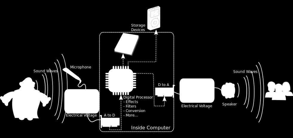
 Chapter 2: Digitization of Sound Acoustics pressure waves are converted to electrical signals by use of a microphone. The output signal from the microphone is an analog signal, i.e., a continuous-valued
ni.com Sensor Measurement Fundamentals Series
 Sensor Measurement Fundamentals Series Introduction to Data Acquisition Basics and Terminology Litkei Márton District Sales Manager National Instruments What Is Data Acquisition (DAQ)? 3 Why Measure? Engineers
Introduction to Internet of Things Prof. Sudip Misra Department of Computer Science & Engineering Indian Institute of Technology, Kharagpur
 Introduction to Internet of Things Prof. Sudip Misra Department of Computer Science & Engineering Indian Institute of Technology, Kharagpur Lecture - 03 Sensing So, we have already understood the basics
Microprocessors & Interfacing
 Lecture overview Microprocessors & Interfacing /Output output PMW Digital-to- (D/A) Conversion input -to-digital (A/D) Conversion Lecturer : Dr. Annie Guo S2, 2008 COMP9032 Week9 1 S2, 2008 COMP9032 Week9
CHAPTER ELEVEN - Interfacing With the Analog World
 CHAPTER ELEVEN - Interfacing With the Analog World 11.1 (a) Analog output = (K) x (digital input) (b) Smallest change that can occur in the analog output as a result of a change in the digital input. (c)
APPLICATION BULLETIN PRINCIPLES OF DATA ACQUISITION AND CONVERSION. Reconstructed Wave Form
 APPLICATION BULLETIN Mailing Address: PO Box 11400 Tucson, AZ 85734 Street Address: 6730 S. Tucson Blvd. Tucson, AZ 85706 Tel: (60) 746-1111 Twx: 910-95-111 Telex: 066-6491 FAX (60) 889-1510 Immediate
Electronic Systems - B1 23/04/ /04/ SisElnB DDC. Chapter 2
 Politecnico di Torino - ICT school Goup B - goals ELECTRONIC SYSTEMS B INFORMATION PROCESSING B.1 Systems, sensors, and actuators» System block diagram» Analog and digital signals» Examples of sensors»
ELECTRONIC SYSTEMS. Introduction. B1 - Sensors and actuators. Introduction
 Politecnico di Torino - ICT school Goup B - goals ELECTRONIC SYSTEMS B INFORMATION PROCESSING B.1 Systems, sensors, and actuators» System block diagram» Analog and digital signals» Examples of sensors»
Analog Input and Output. Lecturer: Sri Parameswaran Notes by: Annie Guo
 Analog Input and Output Lecturer: Sri Parameswaran Notes by: Annie Guo 1 Analog output Lecture overview PMW Digital-to-Analog (D/A) Conversion Analog input Analog-to-Digital (A/D) Conversion 2 PWM Analog
DT9838. Strain- and Bridge-Based Measurement Module. Key Features: Bridge Configurations. Analog Input Features
 Strain- and Bridge-Based Measurement Module The module is a strain gage measurement device intended for full-, half, and quarter-bridge strain gage elements and bridge-based sensor assemblies such as load
Design Implementation Description for the Digital Frequency Oscillator
 Appendix A Design Implementation Description for the Frequency Oscillator A.1 Input Front End The input data front end accepts either analog single ended or differential inputs (figure A-1). The input
Ch 5 Hardware Components for Automation
 Ch 5 Hardware Components for Automation Sections: 1. Sensors 2. Actuators 3. Analog-to-Digital Conversion 4. Digital-to-Analog Conversion 5. Input/Output Devices for Discrete Data Computer-Process Interface
GSM BASED PATIENT MONITORING SYSTEM
 GSM BASED PATIENT MONITORING SYSTEM ABSTRACT This project deals with the monitoring of the patient parameters such as humidity, temperature and heartbeat. Here we have designed a microcontroller based
FYS3240 PC-based instrumentation and microcontrollers. Signal sampling. Spring 2017 Lecture #5
 FYS3240 PC-based instrumentation and microcontrollers Signal sampling Spring 2017 Lecture #5 Bekkeng, 30.01.2017 Content Aliasing Sampling Analog to Digital Conversion (ADC) Filtering Oversampling Triggering
ELG4139: Converters Analog to Digital Converters (ADCs) Digital to Analog Converters (DACs)
 Digital to Analog Converters (DACs)") ELG4139: Converters Analog to Digital Converters (ADCs) Digital to Analog Converters (DACs) Digital Output Dout 111 110 101 100 011 010 001 000 ΔV, V LSB V ref 8 V FS 4 V 8 ref 7 V 8 ref Analog Input V
ELG4139: Converters Analog to Digital Converters (ADCs) Digital to Analog Converters (DACs) Digital Output Dout 111 110 101 100 011 010 001 000 ΔV, V LSB V ref 8 V FS 4 V 8 ref 7 V 8 ref Analog Input V
Analog I/O. ECE 153B Sensor & Peripheral Interface Design Winter 2016
 Analog I/O ECE 153B Sensor & Peripheral Interface Design Introduction Anytime we need to monitor or control analog signals with a digital system, we require analogto-digital (ADC) and digital-to-analog
WebSeminar: Sept. 24, 2003
 The New Digitally Controlled Programmable Gain Amplifier (PGA) 2003 Microchip Technology Incorporated. All Rights Reserved. MCP6S21/2/6/8 The New Digitally Controlled Amplifier (PGA) 1 The New Digitally
16.2 DIGITAL-TO-ANALOG CONVERSION
 240 16. DC MEASUREMENTS In the context of contemporary instrumentation systems, a digital meter measures a voltage or current by performing an analog-to-digital (A/D) conversion. A/D converters produce
DT9838 Strain Measurement Module
 Strain- and Bridge-Based Measurement Module Strain Measurement Module The module is a strain gage measurement device intended for full-, half, and quarter-bridge strain gage elements and bridge-based sensor
Lecture 6: Digital/Analog Techniques
 Lecture 6: Digital/Analog Techniques The electronics signals that we ve looked at so far have been analog that means the information is continuous. A voltage of 5.3V represents different information that
System on a Chip. Prof. Dr. Michael Kraft
 System on a Chip Prof. Dr. Michael Kraft Lecture 5: Data Conversion ADC Background/Theory Examples Background Physical systems are typically analogue To apply digital signal processing, the analogue signal
Learning Objectives:
 Learning Objectives: At the end of this topic you will be able to; Analyse and design a DAC based on an op-amp summing amplifier to meet a given specification. 1 Digital and Analogue Information Module
Sensing. Autonomous systems. Properties. Classification. Key requirement of autonomous systems. An AS should be connected to the outside world.
 Sensing Key requirement of autonomous systems. An AS should be connected to the outside world. Autonomous systems Convert a physical value to an electrical value. From temperature, humidity, light, to
Analogue to Digital Conversion
 Analogue to Digital Conversion Turns electrical input (voltage/current) into numeric value Parameters and requirements Resolution the granularity of the digital values Integral NonLinearity proportionality
EE482: Digital Signal Processing Applications
 Professor Brendan Morris, SEB 3216, brendan.morris@unlv.edu EE482: Digital Signal Processing Applications Spring 2014 TTh 14:30-15:45 CBC C222 Lecture 01 Introduction 14/01/21 http://www.ee.unlv.edu/~b1morris/ee482/
Sensors. Chapter 3. Storey: Electrical & Electronic Systems Pearson Education Limited 2004 OHT 3.1
 Sensors Chapter 3 Introduction Describing Sensor Performance Temperature Sensors Light Sensors Force Sensors Displacement Sensors Motion Sensors Sound Sensors Sensor Interfacing Storey: Electrical & Electronic
CENG4480 Lecture 04: Analog/Digital Conversions
 CENG4480 Lecture 04: Analog/Digital Conversions Bei Yu byu@cse.cuhk.edu.hk (Latest update: October 3, 2018) Fall 2018 1 / 31 Overview Preliminaries Comparator Digital to Analog Conversion (DAC) Analog
EE 421L Digital Electronics Laboratory. Laboratory Exercise #9 ADC and DAC
 EE 421L Digital Electronics Laboratory Laboratory Exercise #9 ADC and DAC Department of Electrical and Computer Engineering University of Nevada, at Las Vegas Objective: The purpose of this laboratory
University of Pittsburgh
 University of Pittsburgh Experiment #7 Lab Report Analog-Digital Applications Submission Date: 08/01/2018 Instructors: Dr. Ahmed Dallal Shangqian Gao Submitted By: Nick Haver & Alex Williams Station #2
DSP Project. Reminder: Project proposal is due Friday, October 19, 2012 by 5pm in my office (Small 239).
.") DSP Project eminder: Project proposal is due Friday, October 19, 2012 by 5pm in my office (Small 239). Budget: $150 for project. Free parts: Surplus parts from previous year s project are available on
DSP Project eminder: Project proposal is due Friday, October 19, 2012 by 5pm in my office (Small 239). Budget: $150 for project. Free parts: Surplus parts from previous year s project are available on
Lab 10. Speed Control of a D.C. motor
 Lab 10. Speed Control of a D.C. motor Speed Measurement: Tach Amplitude Method References: STM32L100 Data Sheet (pin definitions) STM32L100 Ref. Manual (ADC, GPIO, Clocks) Motor Speed Control Project 1.
Analog/Digital and Sampling
 Analog/Digital and Sampling Alexander Nelson October 22, 2018 University of Arkansas - Department of Computer Science and Computer Engineering Analog Signals in the real world are analog signals Process
Design IV. E232 Spring 07
 Design IV Spring 07 Class 8 Bruce McNair bmcnair@stevens.edu 8-1/38 Computerized Data Acquisition Measurement system architecture System under test sensor sensor sensor sensor signal conditioning signal
A DSP IMPLEMENTED DIGITAL FM MULTIPLEXING SYSTEM
 A DSP IMPLEMENTED DIGITAL FM MULTIPLEXING SYSTEM Item Type text; Proceedings Authors Rosenthal, Glenn K. Publisher International Foundation for Telemetering Journal International Telemetering Conference
Embedded System Hardware
 12 Embedded System Hardware Jian-Jia Chen (Slides are based on Peter Marwedel) Informatik 12 TU Dortmund Germany 2015 11 11 These slides use Microsoft clip arts. Microsoft copyright restrictions apply.
SAMPLING AND RECONSTRUCTING SIGNALS
 CHAPTER 3 SAMPLING AND RECONSTRUCTING SIGNALS Many DSP applications begin with analog signals. In order to process these analog signals, the signals must first be sampled and converted to digital signals.
Chapter 7. Introduction. Analog Signal and Discrete Time Series. Sampling, Digital Devices, and Data Acquisition
 Chapter 7 Sampling, Digital Devices, and Data Acquisition Material from Theory and Design for Mechanical Measurements; Figliola, Third Edition Introduction Integrating analog electrical transducers with
Embedded Systems Lecture 2: Interfacing with the Environment. Björn Franke University of Edinburgh
 Embedded Systems Lecture 2: Interfacing with the Environment Björn Franke University of Edinburgh Overview Interfacing with the Physical Environment Signals, Discretisation Input (Sensors) Output (Actuators)
Analog-to-Digital Converter (ADC) And Digital-to-Analog Converter (DAC)
 And Digital-to-Analog Converter (DAC)") 1 Analog-to-Digital Converter (ADC) And Digital-to-Analog Converter (DAC) 2 1. DAC In an electronic circuit, a combination of high voltage (+5V) and low voltage (0V) is usually used to represent a binary
1 Analog-to-Digital Converter (ADC) And Digital-to-Analog Converter (DAC) 2 1. DAC In an electronic circuit, a combination of high voltage (+5V) and low voltage (0V) is usually used to represent a binary
Pulse Code Modulation
 Pulse Code Modulation Modulation is the process of varying one or more parameters of a carrier signal in accordance with the instantaneous values of the message signal. The message signal is the signal
INF4420. ΔΣ data converters. Jørgen Andreas Michaelsen Spring 2012
 INF4420 ΔΣ data converters Spring 2012 Jørgen Andreas Michaelsen (jorgenam@ifi.uio.no) Outline Oversampling Noise shaping Circuit design issues Higher order noise shaping Introduction So far we have considered
EE 230 Lecture 39. Data Converters. Time and Amplitude Quantization
 EE 230 Lecture 39 Data Converters Time and Amplitude Quantization Review from Last Time: Time Quantization How often must a signal be sampled so that enough information about the original signal is available
Measurement system applications. Measurement System
 Measurement system applications Measurement System The Figure above hows a functional block diagram of a simple temperature control system in which the temperature Ta of a room is maintained at a reference
Lesson 7. Digital Signal Processors
 Lesson 7 Digital Signal Processors Instructional Objectives After going through this lesson the student would learn o Architecture of a Real time Signal Processing Platform o Different Errors introduced
Lab 2A: Introduction to Sensing and Data Acquisition
 Lab 2A: Introduction to Sensing and Data Acquisition Prof. R.G. Longoria Department of Mechanical Engineering The University of Texas at Austin June 12, 2014 1 Lab 2A 2 Sensors 3 DAQ 4 Experimentation
Analog-Digital Interface
 Analog-Digital Interface Tuesday 24 November 15 Summary Previous Class Dependability Today: Redundancy Error Correcting Codes Analog-Digital Interface Converters, Sensors / Actuators Sampling DSP Frequency
For the system to have the high accuracy needed for many measurements,
 Sampling and Digitizing Most real life signals are continuous analog voltages. These voltages might be from an electronic circuit or could be the output of a transducer and be proportional to current,
Eliminate Pipeline Headaches with New 12-Bit 3Msps SAR ADC by Dave Thomas and William C. Rempfer
 A new 12-bit 3Msps ADC brings new levels of performance and ease of use to high speed ADC applications. By raising the speed of the successive approximation (SAR) method to 3Msps, it eliminates the many
Tel: Fax:
 B Tel: 78.39.4700 Fax: 78.46.33 SPECIFICATIONS (T A = +5 C, V+ = +5 V, V = V or 5 V, all voltages measured with respect to digital common, unless otherwise noted) AD57J AD57K AD57S Model Min Typ Max Min
ANALOG-TO-DIGITAL CONVERTERS
 ANALOG-TO-DIGITAL CONVERTERS Definition An analog-to-digital converter is a device which converts continuous signals to discrete digital numbers. Basics An analog-to-digital converter (abbreviated ADC,
FYS3240 PC-based instrumentation and microcontrollers. Signal sampling. Spring 2015 Lecture #5
 FYS3240 PC-based instrumentation and microcontrollers Signal sampling Spring 2015 Lecture #5 Bekkeng, 29.1.2015 Content Aliasing Nyquist (Sampling) ADC Filtering Oversampling Triggering Analog Signal Information
Lecture 3: Sensors, signals, ADC and DAC
 Instrumentation and data acquisition Spring 2010 Lecture 3: Sensors, signals, ADC and DAC Zheng-Hua Tan Multimedia Information and Signal Processing Department of Electronic Systems Aalborg University,
Digital Sampling. This Lecture. Engr325 Instrumentation. Dr Curtis Nelson. Digital sampling Sample rate. Bit depth. Other terms. Types of conversion.
 Digital Sampling Engr325 Instrumentation Dr Curtis Nelson Digital sampling Sample rate. Bit depth. Other terms. Types of conversion. This Lecture 1 Data Acquisition and Control Computers are nearly always
The University of Texas at Arlington Lecture 10 ADC and DAC
 The University of Texas at Arlington Lecture 10 ADC and DAC CSE 3442/5442 Measuring Physical Quantities (Digital) computers use discrete values, and use these to emulate continuous values if needed. In
Module 1: Introduction to Experimental Techniques Lecture 2: Sources of error. The Lecture Contains: Sources of Error in Measurement
 The Lecture Contains: Sources of Error in Measurement Signal-To-Noise Ratio Analog-to-Digital Conversion of Measurement Data A/D Conversion Digitalization Errors due to A/D Conversion file:///g /optical_measurement/lecture2/2_1.htm[5/7/2012
CHAPTER 10: DIGITAL INSTRUMENTATION PRINCIPLES
 I. Why digital? CHAPTER 10: DIGITAL INSTRUMENTATION PRINCIPLES Almost all the transducers we have considered so far have had an analog output, that is, the output is a different form from the input but
I hope you have completed Part 2 of the Experiment and is ready for Part 3.
 I hope you have completed Part 2 of the Experiment and is ready for Part 3. In part 3, you are going to use the FPGA to interface with the external world through a DAC and a ADC on the add-on card. You
SU QuarkNet Workshop 2012 Lab Activity 5 ELECTRONICS II: ADCs & DAQ
 SU Lab Activity 5 ELECTRONICS II: ADCs & DAQ Laboratory Goals 1. Learn about data conversion (analog to digital, ADC). 2. Understand how an ADC works, measure the calibration curve, and determine the frequency
Fig 1: The symbol for a comparator
 INTRODUCTION A comparator is a device that compares two voltages or currents and switches its output to indicate which is larger. They are commonly used in devices such as They are commonly used in devices
ADC0808/ADC Bit µp Compatible A/D Converters with 8-Channel Multiplexer
 ADC0808/ADC0809 8-Bit µp Compatible A/D Converters with 8-Channel Multiplexer General Description The ADC0808, ADC0809 data acquisition component is a monolithic CMOS device with an 8-bit analog-to-digital
AERO2705 Space Engineering 1 Week 7 The University of Sydney
 AERO2705 Space Engineering 1 Week 7 The University of Sydney Presenter Mr. Warwick Holmes Executive Director Space Engineering School of Aerospace, Mechanical and Mechatronic Engineering The University
TE 302 DISCRETE SIGNALS AND SYSTEMS. Chapter 1: INTRODUCTION
 TE 302 DISCRETE SIGNALS AND SYSTEMS Study on the behavior and processing of information bearing functions as they are currently used in human communication and the systems involved. Chapter 1: INTRODUCTION
Data Conversion Circuits & Modulation Techniques. Subhasish Chandra Assistant Professor Department of Physics Institute of Forensic Science, Nagpur
 Data Conversion Circuits & Modulation Techniques Subhasish Chandra Assistant Professor Department of Physics Institute of Forensic Science, Nagpur Data Conversion Circuits 2 Digital systems are being used
Developer Techniques Sessions
 1 Developer Techniques Sessions Physical Measurements and Signal Processing Control Systems Logging and Networking 2 Abstract This session covers the technologies and configuration of a physical measurement
Section 1. Fundamentals of DDS Technology
 Section 1. Fundamentals of DDS Technology Overview Direct digital synthesis (DDS) is a technique for using digital data processing blocks as a means to generate a frequency- and phase-tunable output signal