The counterpart to a DAC is the ADC, which is generally a more complicated circuit. One of the most popular ADC circuit is the successive
|
|
|
- Donald Taylor
- 5 years ago
- Views:
Transcription
1 1
2 The counterpart to a DAC is the ADC, which is generally a more complicated circuit. One of the most popular ADC circuit is the successive approximation converter. 2
3 3
4 The idea of sampling is fully covered in the Signal and Linear Systems course. Essentially we quantize an analogue signal in time and in amplitude. Quantizing in time does not loose information as long as the sampling frequency is at least twice the maximum frequency component of the signal you are sampling. Quantising in amplitude is achieved through a ADC and information is lost. The difference between the original analogue signal and the digitized signal is the quantisation noise. 4
5 Take a signal V_IN, digitize this using a ADC to produce X[N-1:0] and then convert this back to analogue using a DAC to produce V_OUT. If you now subtract V_IN from V_OUT, you have the quantization oise. This noise signal has an amplitude of +/- ½ a LSB. If you assume that the input signal is random and therefore the amplitude of the quantisation noise is equally likely to take on a value between - ½ LSB and + ½ LSB, the RMS value of the noise is easily shown to be around 0.3 LSB. What is the Signal-to-Noise ratio of an n-bit converter? This can also be calculated easily. Consider a sine wave with an amplitude of +/- 2^(n-1). We choose this amplitude because this is centred around 0 (no dc component) and 1LSB = 1V, making this easier to express everything in LSB. The RMS value of this sine wave is easily shown to be 0.71 x 2^(n-1) or 0.35 x 2^n. Therefore for such a sine wave, the SNR is n db. In other words, for every extra bit of ADC/DAC resolution, we add an extra 6dB to the SNR. 5
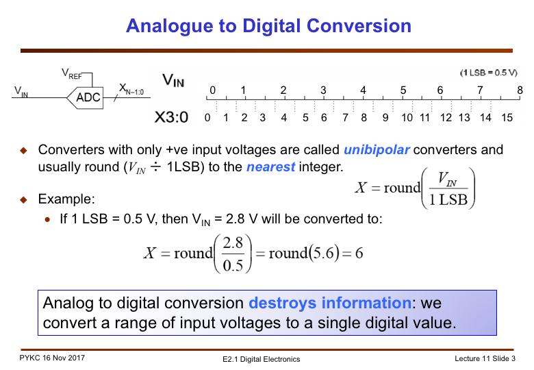
6 Every ADC contains a DAC converter, which provides many threshold voltages. The ADC compares the input voltage to be converter V_IN to these threshold voltages and determine what the converter digital value should be. Each converter value X therefore corresponds to a range of values of V_IN. This range defines the threshold voltages which is X +/- ½ LSB. 6
7 The simplest ADC is the flash ADC. We are converting from the range of 0V to 4V to a digital range of 0 to 7 in binary. A voltage divider with a string of resistors R (which is the DAC circuit) is used to provide all the threshold voltages needed i.e. 0, 0.5, analogue comparators are used to determine which voltage interval V_IN lies. For example, if V_IN = 1.75V, then G1 to G3 are logic 1 and G4 to G7 are 0. This produces the thermometer code which is decoded into a binary number X[2:0]. 7
8 The decoder that maps the thermometer code to binary code is very simple just a truth table, which can be implemented in Verilog as a case statement (similar to the 7-segment decoder example we used before). 8
9 This is a simple ADC using a DAC. The START signal is a short pulse that asynchronously reset the counter to zero. This starts the ADC conversion. If V IN is above the lowest value from DAC, the counter is enable (HIGHER=1). The counter then counts up until V IN is now lower than the DAC output, and counter is disabled, and the DONE signal goes high. X3:0 shows the value of the counter that makes the DAC just over the V_IN value. The disadvantage of this converter is that the time it takes to perform a conversion is dependent on the value of V IN. Furthermore, if this is a 16-bit converter, it could take over 65,000 clock cycles therefore the conversion time can be very long. We will next consider a different scheme using the successive approximation algorithm. 9
10 Let us assume that the input voltage is 2.85V as shown as the RED line. We first set the DAC input X3:0 to 4 b1000 (i.e. assume MSB to be 1 ), and compare V_IN to this threshold. You are effectively dividing the while voltage range into two halves: the lower BLUE range, and the upper RED range. V_IN belongs to the lower BLUE range, so we know setting MSB to 1 is too high. We therefore clear the MSB. 10
11 Next we divide the lower range from 0 to 4V into two equal halves again by setting X3:0 = 4 b0100. The threshold is now 2.0V. We are now testing the second most significant bit to see if this should be 1 or 0. Now V IN belongs to the upper half, therefore we keep the 1 bit which we tested for. 11
12 We now test the next bit by setting X3:0 = 4 b0110, testing X1. We are now dividing the range from 2.0V to 4.0V into two halves. V IN belongs to the lower half, therefore we CLEAR X1. 12
13 Finally we test for the last bit. V IN is in the upper range, hence LSB is 1. We have the final converted digital value: X3:0 = 4 b
14 The hardware architecture for a SA-DAC is shown here. We need to design a FSM to implement the algorithm. It is similar to the counter based ADC we look at earlier, but the counter is now replaced by a state machine that makes decision on whether to reset the 1 -bit which was tested, and what the next DAC value to try. 14
15 The state diagram for the FSM to implement the successive approximation algorithm is shown here. You should be able to walk through this easily. The left most bubble is the starting point, it is initiated when START goes high. We set X3:0 = 4 b1000, i.e. the MSB. If V_IN is higher than the DAC value, it belongs to the upper half, so we take the top transition on the next clock cycle. Otherwise we take the bottom transition. For the top transition, we keep X3 = 1, and set X2 to 1 for the next successive test. For the bottom transition, we reset X3 back to 0 (because X3 = 1 put DAC output in the wrong range), and set X2 to 1. In this way, we trace a path all the way to one of the states in the right most column. The state output provides the final converted result X3:0, and assert the DONE signal (high). 15
16 So far we assume that while the ADC is performing conversion, the input signal is held at a fixed voltage level. If the input signal is in fact changing, the converted digital value will not be an accurate measure of VIN at the time of sampling. To ensure that the ADC input is held at a fixed voltage, we usually include follow-andhold circuit. An analogue switch is normally turn ON, so that VIN is continuously charging the capacitor C. When the START pulse activates the ADC to take a sample, the DONE signal immediately goes low. This should open the switch and hold the VIN value at the time the conversion started. 16
17 A practical sample/hold or follow/hold circuit is shown here using two operation amplifier. This has the advantage that the leakage current from the capacitor can be made very low. During the sampling or following mode, the right most op amp provides strong charging current to charge the capcitor. 17
18 There is another class of converters known as oversampling converters. These use a sigma-delta modulator circuit which sample the input signal at a much high frequency than the Nyquist frequency demands. Normally it produces a 1-bit digital signal which is than down sampled and filtered to produce an accurate analogue output for a DAC, and a multi-bit digital value for a ADC. For example, CD players use an oversample DAC with sampling rate of 6.4MHz. This is then down sampled to produce an output sample rate of 50KHz a oversampling ratio of 128 times. 18
19 19
Electronics A/D and D/A converters
 Electronics A/D and D/A converters Prof. Márta Rencz, Gábor Takács, Dr. György Bognár, Dr. Péter G. Szabó BME DED December 1, 2014 1 / 26 Introduction The world is analog, signal processing nowadays is
Cyber-Physical Systems ADC / DAC
 Cyber-Physical Systems ADC / DAC ICEN 553/453 Fall 2018 Prof. Dola Saha 1 Analog-to-Digital Converter (ADC) Ø ADC is important almost to all application fields Ø Converts a continuous-time voltage signal
Fundamentals of Data Converters. DAVID KRESS Director of Technical Marketing
 Fundamentals of Data Converters DAVID KRESS Director of Technical Marketing 9/14/2016 Analog to Electronic Signal Processing Sensor (INPUT) Amp Converter Digital Processor Actuator (OUTPUT) Amp Converter
ELG3336: Converters Analog to Digital Converters (ADCs) Digital to Analog Converters (DACs)
 Digital to Analog Converters (DACs)") ELG3336: Converters Analog to Digital Converters (ADCs) Digital to Analog Converters (DACs) Digital Output Dout 111 110 101 100 011 010 001 000 ΔV, V LSB V ref 8 V FSR 4 V 8 ref 7 V 8 ref Analog Input
ELG3336: Converters Analog to Digital Converters (ADCs) Digital to Analog Converters (DACs) Digital Output Dout 111 110 101 100 011 010 001 000 ΔV, V LSB V ref 8 V FSR 4 V 8 ref 7 V 8 ref Analog Input
A-D and D-A Converters
 Chapter 5 A-D and D-A Converters (No mathematical derivations) 04 Hours 08 Marks When digital devices are to be interfaced with analog devices (or vice a versa), Digital to Analog converter and Analog
Data Converters. Dr.Trushit Upadhyaya EC Department, CSPIT, CHARUSAT
 Data Converters Dr.Trushit Upadhyaya EC Department, CSPIT, CHARUSAT Purpose To convert digital values to analog voltages V OUT Digital Value Reference Voltage Digital Value DAC Analog Voltage Analog Quantity:
System on a Chip. Prof. Dr. Michael Kraft
 System on a Chip Prof. Dr. Michael Kraft Lecture 5: Data Conversion ADC Background/Theory Examples Background Physical systems are typically analogue To apply digital signal processing, the analogue signal
Analog to Digital Conversion
 Analog to Digital Conversion 02534567998 6 4 2 3 4 5 6 ANALOG to DIGITAL CONVERSION Analog variation (Continuous, smooth variation) Digitized Variation (Discrete set of points) N2 N1 Digitization applied
ELG4139: Converters Analog to Digital Converters (ADCs) Digital to Analog Converters (DACs)
 Digital to Analog Converters (DACs)") ELG4139: Converters Analog to Digital Converters (ADCs) Digital to Analog Converters (DACs) Digital Output Dout 111 110 101 100 011 010 001 000 ΔV, V LSB V ref 8 V FS 4 V 8 ref 7 V 8 ref Analog Input V
ELG4139: Converters Analog to Digital Converters (ADCs) Digital to Analog Converters (DACs) Digital Output Dout 111 110 101 100 011 010 001 000 ΔV, V LSB V ref 8 V FS 4 V 8 ref 7 V 8 ref Analog Input V
Advantages of Analog Representation. Varies continuously, like the property being measured. Represents continuous values. See Figure 12.
 Analog Signals Signals that vary continuously throughout a defined range. Representative of many physical quantities, such as temperature and velocity. Usually a voltage or current level. Digital Signals
Tuesday, March 1st, 9:15 11:00. Snorre Aunet Nanoelectronics group Department of Informatics University of Oslo.
 Nyquist Analog to Digital it Converters Tuesday, March 1st, 9:15 11:00 Snorre Aunet (sa@ifi.uio.no) Nanoelectronics group Department of Informatics University of Oslo 3.1 Introduction 3.1.1 DAC applications
Chapter 5: Signal conversion
 Chapter 5: Signal conversion Learning Objectives: At the end of this topic you will be able to: explain the need for signal conversion between analogue and digital form in communications and microprocessors
Analog to Digital Converters
 Analog to Digital Converters By: Byron Johns, Danny Carpenter Stephanie Pohl, Harry Bo Marr http://ume.gatech.edu/mechatronics_course/fadc_f05.ppt (unless otherwise marked) Presentation Outline Introduction:
Mixed-Signal-Electronics
 1 Mixed-Signal-Electronics PD Dr.-Ing. Stephan Henzler 2 Chapter 6 Nyquist Rate Analog-to-Digital Converters 3 Analog-to-Digital Converter Families Architecture Variant Speed Precision Counting Operation
The simplest DAC can be constructed using a number of resistors with binary weighted values. X[3:0] is the 4-bit digital value to be converter to an
![The simplest DAC can be constructed using a number of resistors with binary weighted values. X[3:0] is the 4-bit digital value to be converter to an](/thumbs/73/68151962.jpg "The simplest DAC can be constructed using a number of resistors with binary weighted values. X[3:0] is the 4-bit digital value to be converter to an") 1 Although digital technology dominates modern electronic systems, the physical world remains mostly analogue in nature. The most important components that link the analogue world to digital systems are
1 Although digital technology dominates modern electronic systems, the physical world remains mostly analogue in nature. The most important components that link the analogue world to digital systems are
High-Speed Analog to Digital Converters. ELCT 1003:High Speed ADCs
 High-Speed Analog to Digital Converters Ann Kotkat Barbara Georgy Mahmoud Tantawi Ayman Sakr Heidi El-Feky Nourane Gamal 1 Outline Introduction. Process of ADC. ADC Specifications. Flash ADC. Pipelined
Lecture 9, ANIK. Data converters 1
 Lecture 9, ANIK Data converters 1 What did we do last time? Noise and distortion Understanding the simplest circuit noise Understanding some of the sources of distortion 502 of 530 What will we do today?
Digital to Analog Conversion. Data Acquisition
 Digital to Analog Conversion (DAC) Digital to Analog Conversion Data Acquisition DACs or D/A converters are used to convert digital signals representing binary numbers into proportional analog voltages.
I hope you have completed Part 2 of the Experiment and is ready for Part 3.
 I hope you have completed Part 2 of the Experiment and is ready for Part 3. In part 3, you are going to use the FPGA to interface with the external world through a DAC and a ADC on the add-on card. You
Analog to Digital Conversion
 Analog to Digital Conversion Florian Erdinger Lehrstuhl für Schaltungstechnik und Simulation Technische Informatik der Uni Heidelberg VLSI Design - Mixed Mode Simulation F. Erdinger, ZITI, Uni Heidelberg
Analog/Digital and Sampling
 Analog/Digital and Sampling Alexander Nelson October 22, 2018 University of Arkansas - Department of Computer Science and Computer Engineering Analog Signals in the real world are analog signals Process
CMOS High Speed A/D Converter Architectures
 CHAPTER 3 CMOS High Speed A/D Converter Architectures 3.1 Introduction In the previous chapter, basic key functions are examined with special emphasis on the power dissipation associated with its implementation.
PHYS225 Lecture 22. Electronic Circuits
 PHYS225 Lecture 22 Electronic Circuits Last lecture Digital to Analog Conversion DAC Converts digital signal to an analog signal Computer control of everything! Various types/techniques for conversion
EE 421L Digital Electronics Laboratory. Laboratory Exercise #9 ADC and DAC
 EE 421L Digital Electronics Laboratory Laboratory Exercise #9 ADC and DAC Department of Electrical and Computer Engineering University of Nevada, at Las Vegas Objective: The purpose of this laboratory
Data Converters. Springer FRANCO MALOBERTI. Pavia University, Italy
 Data Converters by FRANCO MALOBERTI Pavia University, Italy Springer Contents Dedicat ion Preface 1. BACKGROUND ELEMENTS 1.1 1.2 1.3 1.4 1.5 1.6 1.7 1.8 The Ideal Data Converter Sampling 1.2.1 Undersampling
10. Chapter: A/D and D/A converter principles
 Punčochář, Mohylová: TELO, Chapter 10: A/D and D/A converter principles 1 10. Chapter: A/D and D/A converter principles Time of study: 6 hours Goals: the student should be able to define basic principles
Eliminate Pipeline Headaches with New 12-Bit 3Msps SAR ADC by Dave Thomas and William C. Rempfer
 A new 12-bit 3Msps ADC brings new levels of performance and ease of use to high speed ADC applications. By raising the speed of the successive approximation (SAR) method to 3Msps, it eliminates the many
P a g e 1. Introduction
 P a g e 1 Introduction 1. Signals in digital form are more convenient than analog form for processing and control operation. 2. Real world signals originated from temperature, pressure, flow rate, force
2. ADC Architectures and CMOS Circuits
 /58 2. Architectures and CMOS Circuits Francesc Serra Graells francesc.serra.graells@uab.cat Departament de Microelectrònica i Sistemes Electrònics Universitat Autònoma de Barcelona paco.serra@imb-cnm.csic.es
Data Conversion Techniques (DAT115)
") Data Conversion Techniques (DAT115) Hand in Report Second Order Sigma Delta Modulator with Interleaving Scheme Group 14N Remzi Yagiz Mungan, Christoffer Holmström [ 1 20 ] Contents 1. Task Description...
Data Conversion Techniques (DAT115) Hand in Report Second Order Sigma Delta Modulator with Interleaving Scheme Group 14N Remzi Yagiz Mungan, Christoffer Holmström [ 1 20 ] Contents 1. Task Description...
Assoc. Prof. Dr. Burak Kelleci
 DEPARTMENT OF ELECTRICAL &ELECTRONICS ENGINEERING ANALOG-TO-DIGITAL AND DIGITAL- TO-ANALOG CONVERTERS Assoc. Prof. Dr. Burak Kelleci Fall 2018 OUTLINE Nyquist-Rate DAC Thermometer-Code Converter Hybrid
DSP Project. Reminder: Project proposal is due Friday, October 19, 2012 by 5pm in my office (Small 239).
.") DSP Project eminder: Project proposal is due Friday, October 19, 2012 by 5pm in my office (Small 239). Budget: $150 for project. Free parts: Surplus parts from previous year s project are available on
DSP Project eminder: Project proposal is due Friday, October 19, 2012 by 5pm in my office (Small 239). Budget: $150 for project. Free parts: Surplus parts from previous year s project are available on
UNIVERSITY OF NORTH CAROLINA AT CHARLOTTE Department of Electrical and Computer Engineering
 UNIVERSITY OF NORTH CAROLINA AT CHARLOTTE Department of Electrical and Computer Engineering EXPERIMENT 10 ANALOG-TO-DIGITAL AND DIGITAL-TO-ANALOG CONVERSION OBJECTIVES The purpose of this experiment is
ANALOG TO DIGITAL (ADC) and DIGITAL TO ANALOG CONVERTERS (DAC)
 and DIGITAL TO ANALOG CONVERTERS (DAC)") COURSE / CODE DIGITAL SYSTEM FUNDAMENTALS (ECE421) DIGITAL ELECTRONICS FUNDAMENTAL (ECE422) ANALOG TO DIGITAL (ADC) and DIGITAL TO ANALOG CONVERTERS (DAC) Connecting digital circuitry to sensor devices
COURSE / CODE DIGITAL SYSTEM FUNDAMENTALS (ECE421) DIGITAL ELECTRONICS FUNDAMENTAL (ECE422) ANALOG TO DIGITAL (ADC) and DIGITAL TO ANALOG CONVERTERS (DAC) Connecting digital circuitry to sensor devices
Lecture #6: Analog-to-Digital Converter
 Lecture #6: Analog-to-Digital Converter All electrical signals in the real world are analog, and their waveforms are continuous in time. Since most signal processing is done digitally in discrete time,
Outline. Analog/Digital Conversion
 Analog/Digital Conversion The real world is analog. Interfacing a microprocessor-based system to real-world devices often requires conversion between the microprocessor s digital representation of values
MSP430 Teaching Materials
 MSP430 Teaching Materials Chapter 9 Data Acquisition A/D Conversion Introduction Texas Instruments t Incorporated University of Beira Interior (PT) Pedro Dinis Gaspar, António Espírito Santo, Bruno Ribeiro,
ECE 6770 FINAL PROJECT
 ECE 6770 FINAL PROJECT POINT TO POINT COMMUNICATION SYSTEM Submitted By: Omkar Iyer (Omkar_iyer82@yahoo.com) Vamsi K. Mudarapu (m_vamsi_krishna@yahoo.com) MOTIVATION Often in the real world we have situations
10 bit Delta Sigma D/A Converter with Increased S/N ratio Using Compact Adder Circuits
 International Journal of Scientific & Engineering Research, Volume 4, Issue 8, August 2013 10 bit Delta Sigma D/A Converter with Increased S/N ratio Using Compact Adder Circuits Jyothish Chandran G, Shajimon
Lab 7: DELTA AND SIGMA-DELTA A/D CONVERTERS
 ANALOG & TELECOMMUNICATION ELECTRONICS LABORATORY EXERCISE 6 Lab 7: DELTA AND SIGMA-DELTA A/D CONVERTERS Goal The goals of this experiment are: - Verify the operation of a differential ADC; - Find the
CHAPTER. delta-sigma modulators 1.0
 CHAPTER 1 CHAPTER Conventional delta-sigma modulators 1.0 This Chapter presents the traditional first- and second-order DSM. The main sources for non-ideal operation are described together with some commonly
Learning Objectives:
 Learning Objectives: At the end of this topic you will be able to; Analyse and design a DAC based on an op-amp summing amplifier to meet a given specification. 1 Digital and Analogue Information Module
Analog-to-Digital i Converters
 CSE 577 Spring 2011 Analog-to-Digital i Converters Jaehyun Lim, Kyusun Choi Department t of Computer Science and Engineering i The Pennsylvania State University ADC Glossary DNL (differential nonlinearity)
The need for Data Converters
 The need for Data Converters ANALOG SIGNAL (Speech, Images, Sensors, Radar, etc.) PRE-PROCESSING (Filtering and analog to digital conversion) DIGITAL PROCESSOR (Microprocessor) POST-PROCESSING (Digital
CHAPTER ELEVEN - Interfacing With the Analog World
 CHAPTER ELEVEN - Interfacing With the Analog World 11.1 (a) Analog output = (K) x (digital input) (b) Smallest change that can occur in the analog output as a result of a change in the digital input. (c)
Analog to digital and digital to analog converters
 Analog to digital and digital to analog converters A/D converter D/A converter ADC DAC ad da Number bases Decimal, base, numbers - 9 Binary, base, numbers and Oktal, base 8, numbers - 7 Hexadecimal, base
Lab.3. Tutorial : (draft) Introduction to CODECs
 Introduction to CODECs") Lab.3. Tutorial : (draft) Introduction to CODECs Fig. Basic digital signal processing system Definition A codec is a device or computer program capable of encoding or decoding a digital data stream or
Lab.3. Tutorial : (draft) Introduction to CODECs Fig. Basic digital signal processing system Definition A codec is a device or computer program capable of encoding or decoding a digital data stream or
Fill in the following worksheet-style pages. A colored pen or pencil works best. The procedure is:
 14: ALIASING I. PRELAB FOR ALIASING LAB You might expect that to record a frequency of 4000 Hz you would have to sample at a rate of at least 4000 Hz. It turns out, however, that you actually have to sample
EE 308 Spring Using the HCS12 PWM
 Using the HCS12 PWM 1. Choose 8-bit mode (PWMCTL = x) 2. Choose high polarity (PWMPOL = xff) 3. Choose left-aligned (PWMCAE = x) 4. Select clock mode in PWMCLK: PCLKn = for 2 N, PCLKn = 1 for 2 (N+1) M,
Linear Integrated Circuits
 Linear Integrated Circuits Single Slope ADC Comparator checks input voltage with integrated reference voltage, V REF At the same time the number of clock cycles is being counted. When the integrator output
PART TOP VIEW V EE 1 V CC 1 CONTROL LOGIC
 19-1331; Rev 1; 6/98 EVALUATION KIT AVAILABLE Upstream CATV Driver Amplifier General Description The MAX3532 is a programmable power amplifier for use in upstream cable applications. The device outputs
FYS3240 PC-based instrumentation and microcontrollers. Signal sampling. Spring 2017 Lecture #5
 FYS3240 PC-based instrumentation and microcontrollers Signal sampling Spring 2017 Lecture #5 Bekkeng, 30.01.2017 Content Aliasing Sampling Analog to Digital Conversion (ADC) Filtering Oversampling Triggering
Analogue to Digital Conversion
 Analogue to Digital Conversion Turns electrical input (voltage/current) into numeric value Parameters and requirements Resolution the granularity of the digital values Integral NonLinearity proportionality
IJSRD - International Journal for Scientific Research & Development Vol. 4, Issue 04, 2016 ISSN (online):
:") IJSRD - International Journal for Scientific Research & Development Vol. 4, Issue 04, 2016 ISSN (online): 2321-0613 Designing and FFT Analysis of Sigma Delta Converter using Spice Ritika Bathri 1 Prachi
IJSRD - International Journal for Scientific Research & Development Vol. 4, Issue 04, 2016 ISSN (online): 2321-0613 Designing and FFT Analysis of Sigma Delta Converter using Spice Ritika Bathri 1 Prachi
EEE312: Electrical measurement & instrumentation
 University of Turkish Aeronautical Association Faculty of Engineering EEE department EEE312: Electrical measurement & instrumentation Digital Electronic meters BY Ankara March 2017 1 Introduction The digital
CONTINUOUS DIGITAL CALIBRATION OF PIPELINED A/D CONVERTERS
 CONTINUOUS DIGITAL CALIBRATION OF PIPELINED A/D CONVERTERS By Alma Delić-Ibukić B.S. University of Maine, 2002 A THESIS Submitted in Partial Fulfillment of the Requirements for the Degree of Master of
ISSN:
 1391 DESIGN OF 9 BIT SAR ADC USING HIGH SPEED AND HIGH RESOLUTION OPEN LOOP CMOS COMPARATOR IN 180NM TECHNOLOGY WITH R-2R DAC TOPOLOGY AKHIL A 1, SUNIL JACOB 2 1 M.Tech Student, 2 Associate Professor,
EE247 Lecture 22. Figures of merit (FOM) and trends for ADCs How to use/not use FOM. EECS 247 Lecture 22: Data Converters 2004 H. K.
 and trends for ADCs How to use/not use FOM. EECS 247 Lecture 22: Data Converters 2004 H. K.") EE247 Lecture 22 Pipelined ADCs Combining the bits Stage implementation Circuits Noise budgeting Figures of merit (FOM) and trends for ADCs How to use/not use FOM Oversampled ADCs EECS 247 Lecture 22:
EE247 Lecture 22 Pipelined ADCs Combining the bits Stage implementation Circuits Noise budgeting Figures of merit (FOM) and trends for ADCs How to use/not use FOM Oversampled ADCs EECS 247 Lecture 22:
Data Acquisition & Computer Control
 Chapter 4 Data Acquisition & Computer Control Now that we have some tools to look at random data we need to understand the fundamental methods employed to acquire data and control experiments. The personal
10 Speech and Audio Signals
 0 Speech and Audio Signals Introduction Speech and audio signals are normally converted into PCM, which can be stored or transmitted as a PCM code, or compressed to reduce the number of bits used to code
EECS 373 Design of Microprocessor-Based Systems
 EECS 373 Design of Microprocessor-Based Systems Prabal Dutta University of Michigan Lecture 11: Sampling, ADCs, and DACs Oct 7, 2014 Some slides adapted from Mark Brehob, Jonathan Hui & Steve Reinhardt
Design of an 8-bit Successive Approximation Pipelined Analog to Digital Converter (SAP- ADC) in 90 nm CMOS
 in 90 nm CMOS") Design of an 8-bit Successive Approximation Pipelined Analog to Digital Converter (SAP- ADC) in 90 nm CMOS A thesis submitted in partial fulfillment of the requirements for the degree of Master of Science
Design of an 8-bit Successive Approximation Pipelined Analog to Digital Converter (SAP- ADC) in 90 nm CMOS A thesis submitted in partial fulfillment of the requirements for the degree of Master of Science
Sigma-Delta ADC Tutorial and Latest Development in 90 nm CMOS for SoC
 Sigma-Delta ADC Tutorial and Latest Development in 90 nm CMOS for SoC Jinseok Koh Wireless Analog Technology Center Texas Instruments Inc. Dallas, TX Outline Fundamentals for ADCs Over-sampling and Noise
3. DAC Architectures and CMOS Circuits
 1/30 3. DAC Architectures and CMOS Circuits Francesc Serra Graells francesc.serra.graells@uab.cat Departament de Microelectrònica i Sistemes Electrònics Universitat Autònoma de Barcelona paco.serra@imb-cnm.csic.es
Lecture 6: Digital/Analog Techniques
 Lecture 6: Digital/Analog Techniques The electronics signals that we ve looked at so far have been analog that means the information is continuous. A voltage of 5.3V represents different information that
Software Programmable Gain Amplifier AD526
 a FEATURES Digitally Programmable Binary Gains from to 6 Two-Chip Cascade Mode Achieves Binary Gain from to 256 Gain Error: 0.0% Max, Gain =, 2, 4 (C Grade) 0.02% Max, Gain = 8, 6 (C Grade) 0.5 ppm/ C
Chapter 2 Signal Conditioning, Propagation, and Conversion
 09/0 PHY 4330 Instrumentation I Chapter Signal Conditioning, Propagation, and Conversion. Amplification (Review of Op-amps) Reference: D. A. Bell, Operational Amplifiers Applications, Troubleshooting,
Analogue to Digital Conversion
 Analogue to Digital Conversion Turns electrical input (voltage/current) into numeric value Parameters and requirements Resolution the granularity of the digital values Integral NonLinearity proportionality
EE 435. Lecture 41. ADC Design
 EE 435 Lecture 4 ADC Design Nyqyist ate Usage Structures. eview from last lecture. 0 esolution 6 SA Pipeline 8 4 Flash K 0K 00K M 0M 00M G 0G Speed . eview from last lecture. SA ADC C LK IN EF DAC n DAC
Electronic circuits II Example set of questions Łódź 2013
 (V) (V) (V) (V) Electronic circuits II Example set of questions Łódź 213 1) Explain difference between the noise and the distortion. 2) Explain difference between the noise and the interference. 3) Explain
CENG4480 Lecture 04: Analog/Digital Conversions
 CENG4480 Lecture 04: Analog/Digital Conversions Bei Yu byu@cse.cuhk.edu.hk (Latest update: October 3, 2018) Fall 2018 1 / 31 Overview Preliminaries Comparator Digital to Analog Conversion (DAC) Analog
Care and Feeding of the One Bit Digital to Analog Converter
 1 Care and Feeding of the One Bit Digital to Analog Converter Jim Thompson, University of Washington, 8 June 1995 Introduction The one bit digital to analog converter (DAC) is a magical circuit that accomplishes
FYS3240 PC-based instrumentation and microcontrollers. Signal sampling. Spring 2015 Lecture #5
 FYS3240 PC-based instrumentation and microcontrollers Signal sampling Spring 2015 Lecture #5 Bekkeng, 29.1.2015 Content Aliasing Nyquist (Sampling) ADC Filtering Oversampling Triggering Analog Signal Information
EE251: Tuesday October 10
 EE251: Tuesday October 10 Analog to Digital Conversion Text Chapter 20 through section 20.2 TM4C Data Sheet Chapter 13 Lab #5 Writeup Lab Practical #1 this week Homework #4 is due on Thursday at 4:30 p.m.
Analog I/O. ECE 153B Sensor & Peripheral Interface Design Winter 2016
 Analog I/O ECE 153B Sensor & Peripheral Interface Design Introduction Anytime we need to monitor or control analog signals with a digital system, we require analogto-digital (ADC) and digital-to-analog
How do ADCs work? Martin Rowe, Senior Technical Editor -- 7/1/2002 Test & Measurement World

Winter 14 EXAMINATION Subject Code: Model Answer P a g e 1/28
 Subject Code: 17333 Model Answer P a g e 1/28 Important Instructions to examiners: 1) The answers should be examined by key words and not as word-to-word as given in the model answer scheme. 2) The model
A Successive Approximation ADC based on a new Segmented DAC
 A Successive Approximation ADC based on a new Segmented DAC segmented current-mode DAC successive approximation ADC bi-direction segmented current-mode DAC DAC INL 0.47 LSB DNL 0.154 LSB DAC 3V 8 2MS/s
EE 435. Lecture 32. DAC Design. Parasitic Capacitances. The String DAC
 EE 435 Lecture 32 DAC Design The String DAC Parasitic Capacitances . eview from last lecture. DFT Simulation from Matlab . eview from last lecture. Summary of time and amplitude quantization assessment
Care and Feeding of the One Bit Digital to Analog Converter
 Care and Feeding of the One Bit Digital to Analog Converter Jim Thompson, University of Washington, 8 June 1995 Introduction The one bit digital to analog converter (DAC) is a magical circuit that accomplishes
An Overview of the Decimation process and its VLSI implementation
 MPRA Munich Personal RePEc Archive An Overview of the Decimation process and its VLSI implementation Rozita Teymourzadeh and Masuri Othman UKM University 1. February 2006 Online at http://mpra.ub.uni-muenchen.de/41945/
CMOS ADC & DAC Principles
 CMOS ADC & DAC Principles Willy Sansen KULeuven, ESAT-MICAS Leuven, Belgium willy.sansen@esat.kuleuven.be Willy Sansen 10-05 201 Table of contents Definitions Digital-to-analog converters Resistive Capacitive
Data Converters. Lecture Fall2013 Page 1
 Data Converters Lecture Fall2013 Page 1 Lecture Fall2013 Page 2 Representing Real Numbers Limited # of Bits Many physically-based values are best represented with realnumbers as opposed to a discrete number
NPTEL. VLSI Data Conversion Circuits - Video course. Electronics & Communication Engineering.
 NPTEL Syllabus VLSI Data Conversion Circuits - Video course COURSE OUTLINE This course covers the analysis and design of CMOS Analog-to-Digital and Digital-to-Analog Converters,with about 7 design assigments.
UNIT III Data Acquisition & Microcontroller System. Mr. Manoj Rajale
 UNIT III Data Acquisition & Microcontroller System Mr. Manoj Rajale Syllabus Interfacing of Sensors / Actuators to DAQ system, Bit width, Sampling theorem, Sampling Frequency, Aliasing, Sample and hold
A REVIEW ON 4 BIT FLASH ANALOG TO DIGITAL CONVERTOR
 RESEARCH ARTICLE OPEN ACCESS A REVIEW ON 4 BIT FLASH ANALOG TO DIGITAL CONVERTOR Vijay V. Chakole 1, Prof. S. R. Vaidya 2, Prof. M. N. Thakre 3 1 MTech Scholar, S. D. College of Engineering, Selukate,
Choosing the Best ADC Architecture for Your Application Part 3:
 Choosing the Best ADC Architecture for Your Application Part 3: Hello, my name is Luis Chioye, I am an Applications Engineer with the Texas Instruments Precision Data Converters team. And I am Ryan Callaway,
L9: Analog Building Blocks (OpAmps,, A/D, D/A)
") L9: Analog Building Blocks (OpAmps,, A/D, D/A) Acknowledgement: Dave Wentzloff Introduction to Operational Amplifiers DC Model Typically very high input resistance ~ 300KΩ v id in a v id out High DC gain
L9: Analog Building Blocks (OpAmps,, A/D, D/A) Acknowledgement: Dave Wentzloff Introduction to Operational Amplifiers DC Model Typically very high input resistance ~ 300KΩ v id in a v id out High DC gain
Implementation of High Precision Time to Digital Converters in FPGA Devices
 Implementation of High Precision Time to Digital Converters in FPGA Devices Tobias Harion () Implementation of HPTDCs in FPGAs January 22, 2010 1 / 27 Contents: 1 Methods for time interval measurements
Electronics II Physics 3620 / 6620
 Electronics II Physics 3620 / 6620 Feb 09, 2009 Part 1 Analog-to-Digital Converters (ADC) 2/8/2009 1 Why ADC? Digital Signal Processing is more popular Easy to implement, modify, Low cost Data from real
UNIVERSITY OF CALIFORNIA College of Engineering Department of Electrical Engineering and Computer Sciences
 UNIVERSITY OF CALIFORNIA College of Engineering Department of Electrical Engineering and Computer Sciences Final Exam EECS 247 H. Khorramabadi Tues., Dec. 14, 2010 FALL 2010 Name: SID: Total number of
Chapter 4 Digital Transmission 4.1
 Chapter 4 Digital Transmission 4.1 Copyright The McGraw-Hill Companies, Inc. Permission required for reproduction or display. 4-2 ANALOG-TO-DIGITAL CONVERSION We have seen in Chapter 3 that a digital signal
Data Conversion and Lab Lab 4 Fall Digital to Analog Conversions
 Digital to Analog Conversions Objective o o o o o To construct and operate a binary-weighted DAC To construct and operate a Digital to Analog Converters Testing the ADC and DAC With DC Input Testing the
Enhancing Analog Signal Generation by Digital Channel Using Pulse-Width Modulation
 Enhancing Analog Signal Generation by Digital Channel Using Pulse-Width Modulation Angelo Zucchetti Advantest angelo.zucchetti@advantest.com Introduction Presented in this article is a technique for generating
MEDIUM SPEED ANALOG-DIGITAL CONVERTERS
 CMOS Analog IC Design Page 10.7-1 10.7 - MEDIUM SPEED ANALOG-DIGITAL CONVERTERS INTRODUCTION Successive Approximation Algorithm: 1.) Start with the MSB bit and work toward the LSB bit. 2.) Guess the MSB
L9: Analog Building Blocks (OpAmps, A/D, D/A)
") L9: Analog Building Blocks (OpAmps, A/D, D/A) Courtesy of Dave Wentzloff. Used with permission. 1 Introduction to Operational Amplifiers v id in DC Model a v id LM741 Pinout out 10 to 15V Typically very
L9: Analog Building Blocks (OpAmps, A/D, D/A) Courtesy of Dave Wentzloff. Used with permission. 1 Introduction to Operational Amplifiers v id in DC Model a v id LM741 Pinout out 10 to 15V Typically very
Low Power Design of Successive Approximation Registers
 Low Power Design of Successive Approximation Registers Rabeeh Majidi ECE Department, Worcester Polytechnic Institute, Worcester MA USA rabeehm@ece.wpi.edu Abstract: This paper presents low power design
Lab Exercise 6: Digital/Analog conversion
 Lab Exercise 6: Digital/Analog conversion Introduction In this lab exercise, you will study circuits for analog-to-digital and digital-to-analog conversion Preparation Before arriving at the lab, you should
8-Bit, high-speed, µp-compatible A/D converter with track/hold function ADC0820
 8-Bit, high-speed, µp-compatible A/D converter with DESCRIPTION By using a half-flash conversion technique, the 8-bit CMOS A/D offers a 1.5µs conversion time while dissipating a maximum 75mW of power.
ANALYSIS, DESIGN AND IMPLEMENTATION OF NOISE SHAPING DATA CONVERTERS FOR POWER SYSTEMS
 ANALYSIS, DESIGN AND IMPLEMENTATION OF NOISE SHAPING DATA CONVERTERS FOR POWER SYSTEMS Maraim Asif 1, Prof Pallavi Bondriya 2 1 Department of Electrical and Electronics Engineering, Technocrats institute