Module 13: Interfacing ADC. Introduction ADC Programming DAC Programming Sensor Interfacing
|
|
|
- Adrian Rose
- 6 years ago
- Views:
Transcription

1 Module 13: Interfacing ADC Introduction ADC Programming DAC Programming Sensor Interfacing
2 Introduction
3 ADC Devices o Analog-to-digital converters (ADC) are among the most widely used devices for data acquisition. o Digital computer use binary (discrete), but physical world everything is analog (continuous). o Thus a device called transducer (sensor) is needed to convert physical quantities (i.e. temperature, pressure, etc) to electrical (voltage/current) signal. o ADC is used to translate the analog signals to digital signal.

4 ADC Characteristics o In ATmega32, an n-bit ADC is used to translate the analog signals to digital signal so that micro-p can read and process them. o Some of the major characteristics of ADC that we need to know. 1. Resolution ADC has n-bit resolution (8, 10, 12, 16..) Higher-resolution ADCs provide smaller step size- smallest change can be discerned by an ADC. Although ADC resolution is fixed, but the step size can be controlled by Vref.
5 2. Conversion time ADC Characteristics Conversion time is time ADC takes to convert the analog input to digital number. 3. Vref Vref is input voltage used for reference voltage. The voltage connected to this pin, along with ADC resolution, will dictate the step size. 4. Digital data output In an 8-bit ADC, we have an 8-bit digital data output of D0-D7. Thus, Dout:

6 ADC Characteristics 5. Parallel vs Serial ADC Parallel ADC 8 or more pins dedicated to bring out the binary data. Serial ADC Only one pin for data out.
7 ADC Characteristics 6. Analog input channel Many data acquisition application need more than one ADC. Thus, ADC chips comes with 2, 4, 8 or even 16 channels on a single chip. 7. Successive approximate ADC Widely used to convert analog input to digital input. Hass thee main components: successive approximation register (SAR); comparator; control unit.
8 ADC Programming
9 ATmega32 ADC Features o ADC peripheral of ATmega32 has the following characteristics: bit ADC. 2. Has 8 analog input channels, 7 differential input channels and 2 differential input channel with optional gain of 10x and 200x. 3. The converted output binary data is held by two special function registers: ADCL (A/D Result Low) & ADCH (A/D Result High). 4. Since ADCH:ADCL gives us 16-bit and ADC data out only 10-bit, thus remaining 6-bit is unused. 5. Three option for Vref. Vref connected to AVCC (analog Vcc); internal 2.6V reference;, external AREF pin. 6. Conversion time dictated by crystal frequency connected to XTAL and ADPS0:2 bits.

10
11 ADC Connection & Programming o Used inductor and capacitor in order to get a stable voltage source to the AVCC pin. o In ATmega32, five major registers are associated with ADC: 1. ADCH (high data) 2. ADCL (low data) Store result after conversion 3. ADCSRA (ADC Control and Status Register) 4. ADMUX (ADC multiplexer selection register) 5. SPIOR (Special Function I/O Register)


12 o There are three option for Vref selection: 1. AREF pin 2. AVCC pin 3. Internal 2.56V o The REFS1:0 bit 7:6 in ADMUX will determine the Vref. ADMUX Register

13 ADMUX Register o The MUX4:0 bit 4:0 in ADMUX will determine the analog channel and gain selection to be used. o Either single-ended or differential input can be selected to be converted to digital data. o If single-ended is selected, you can chooses input channel among ADC0 to ADC7 single pin is used as analog line, and GND as common ground.
14 ADMUX Register o If differential input is selected, you can chooses input channel as well as the op-amp gain: 1x, 10x, 200x.
15 ADMUX Register o The ADLAR bit 5 in ADMUX will determine either the left bits or the right bits of ADCH:ADCL registers used to store the result. o AVRs have a 10-bit ADC, but since two 8-bit registers dedicated to ADC result (ADCH:ADCL), thus 6 bits are unused and need to select position which bits are used and not. o Set One 1 : left justified. o Set Zero 0 : right justified.
16 ADCH:ADCL Registers o ADCH:ADCL registers are used to store the results after the A/D conversion is complete. o Since the ADC is 10-bit while ADCH:ADCL are 16-bit, we need to set the ADLAR bit of the ADMUX for making it right-justified or left-justified.
17 ADCSRA Register o The ADCSRA register is the status and control register of ADC.
18 ADCSRA Register o The ADPS2:0 Bit 2:0 : ADC Prescaler/Conversion time o These bits will determine the division factor between XTAL frequency and the input clock of ADC. o To select conversion time, we can select any of Fosc/2, Fosc/4, Fosc/8, Fosc/16, Fosc/32, Fosc/64 or Fosc/128 for ADC clock. o Fosc is the speed of the crystal frequency connected to AVR. o For the AVR, ADC requires an input clock frequency less than 200 KHz for the maximum accuracy.

19 ADCSRA Register
20 Steps Programming the ADC using Polling 1. Make the pin for selected ADC channel as an input pin. 2. Turn ON ADC module, since its disable upon power-on-reset to save power. 3. Select conversion speed ADPS2:0 4. Select voltage reference (REFS1:0) and ADC input channel (MUX4:0) in ADMUX register. 5. Activate start conversion bit write 1 to ADSC of ADCSRA register. 6. Wait for the conversion to be completed by polling the ADIF bit of ADCSRA register. 7. After ADIF = HIGH 1, read ADCH:ADCL to get digital data output. * read ADCL before ADCH. 8. If want to read the selected channel again, go back to step If want to select another Vref source or input channel, go back to step 4.
21 Steps Programming the ADC using Polling: Example
22 Steps Programming the ADC using Polling: Example
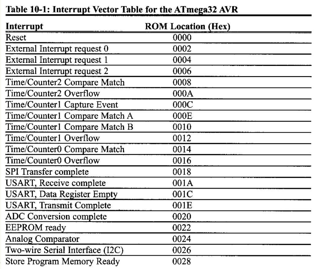
23 Steps Programming the ADC using Interrupt 1. Initialize interrupt vector table. 2. Make the pin for selected ADC channel as an input pin. 3. Turn ON ADC module, since its disable upon power-on-reset to save power. 4. Select conversion speed ADPS2:0 5. Select voltage reference (REFS1:0) and ADC input channel (MUX4:0) in ADMUX register. 6. Activate start conversion bit write 1 to ADSC of ADCSRA register. 7. Set ADIE = HIGH (A/D interrupt enable). Upon completion of conversion, ADIF changes to HIGH. 8. If ADIF = HIGH 1, it force CPU to jump to ADC interrupt handler to read ADCH:ADCL to get digital data output. * read ADCL before ADCH. 9. If want to read the selected channel again, go back to step If want to select another Vref source or input channel, go back to step 4.
24
25 Steps Programming the ADC using Interrupt
26 Steps Programming the ADC using Interrupt
27 DAC Programming
28 Digital-to-Analog Converter (DAC) o DAC widely used to convert digital pulses to analog signals. o There are two methods of creating DAC: 1. Binary weighted 2. R/2R ladder to achieve higher degree of precision. (DAC0808).

29 DAC0808 o In DAC0808, the digital inputs are converted to current (Iout), and by connecting resistor to the Iout, we convert the result to voltage. o Iref is the input current that must be applied to pin 14.
30 Sensor Interfacing
Microcontroller Systems. ELET 3232 Topic 21: ADC Basics
 Microcontroller Systems ELET 3232 Topic 21: ADC Basics Objectives To understand the modes and features of the Analog-to-Digital Converter on the ATmega 128 To understand how to perform an Analog-to-Digital
EE 308: Microcontrollers
 EE 308: Microcontrollers Timers Aly El-Osery Electrical Engineering Department New Mexico Institute of Mining and Technology Socorro, New Mexico, USA April 2, 2018 Aly El-Osery (NMT) EE 308: Microcontrollers
Analogue to Digital Conversion on an ATmega168
 1800 335 330 Shopping Cart: Empty Login or Create Account About Blog Tutorials Library Contact Search... Go Home» Blog» Tutorials» Analogue to Digital Conversion on an ATmega168 Categories Boards Connectors
Embedded Systems and Software. Analog to Digital Conversion
 Embedded Systems and Software Analog to Digital Conversion Slide 1 Analog to Digital Conversion Analog or continuous signal Discrete-time or digital signal Other terms ADC, A/D Many different techniques
Lecture #4 Outline. Announcements Project Proposal. AVR Processor Resources
 October 11, 2002 Stanford University - EE281 Lecture #4 #1 Announcements Project Proposal Lecture #4 Outline AVR Processor Resources A/D Converter (Analog to Digital) Analog Comparator Real-Time clock
EEE3410 Microcontroller Applications Department of Electrical Engineering. Lecture 10. Analogue Interfacing. Vocational Training Council, Hong Kong.
 Department of Electrical Engineering Lecture 10 Analogue Interfacing 1 In this Lecture. Interface 8051 with the following Input/Output Devices Transducer/Sensors Analogue-to-Digital Conversion (ADC) Digital-to-Analogue
The University of Texas at Arlington Lecture 10 ADC and DAC
 The University of Texas at Arlington Lecture 10 ADC and DAC CSE 3442/5442 Measuring Physical Quantities (Digital) computers use discrete values, and use these to emulate continuous values if needed. In
DASL 120 Introduction to Microcontrollers
 DASL 120 Introduction to Microcontrollers Lecture 2 Introduction to 8-bit Microcontrollers Introduction to 8-bit Microcontrollers Introduction to 8-bit Microcontrollers Introduction to Atmel Atmega328
P a g e 1. Introduction
 P a g e 1 Introduction 1. Signals in digital form are more convenient than analog form for processing and control operation. 2. Real world signals originated from temperature, pressure, flow rate, force
Embedded Hardware Design Lab4
 Embedded Hardware Design Lab4 Objective: Controlling the speed of dc motor using light sensor (LDR). In this lab, we would want to control the speed of a DC motor with the help of light sensor. This would
Hardware and software resources on the AVR family for the microcontroller project
 Hardware and software resources on the AVR family for the microcontroller project 1 1. Code Vision The C Compiler you use: CodeVisionAVR (CVAVR) Where can you find it? a (limited) version is available
Design with Microprocessors
 Design with Microprocessors Lecture 9 Year 3 CS Academic year 2017/2018 1 st Semester Lecturer: Radu Dănescu Analog Comparator AIN+ AIN- Compares the analog values from AIN+ (positive) & AIN- (negative)
Roland Kammerer. 13. October 2010
 Peripherals Roland Institute of Computer Engineering Vienna University of Technology 13. October 2010 Overview 1. Analog/Digital Converter (ADC) 2. Pulse Width Modulation (PWM) 3. Serial Peripheral Interface
8-bit Microcontroller with 1K Bytes Flash. ATtiny15. Advance Information. Features. Description. Pin Configurations
 Features High-performance, Low-power AVR 8-bit Microcontroller RISC Architecture 90 Powerful Instructions - Most Single Clock Cycle Execution 32 x 8 General Purpose Working Registers Fully Static Operation
MICROPROCESSORS A (17.383) Fall Lecture Outline
 Fall Lecture Outline") MICROPROCESSORS A (17.383) Fall 2010 Lecture Outline Class # 07 October 26, 2010 Dohn Bowden 1 Today s Lecture Syllabus review Microcontroller Hardware and/or Interface Finish Analog to Digital Conversion
MICROPROCESSORS A (17.383) Fall 2010 Lecture Outline Class # 07 October 26, 2010 Dohn Bowden 1 Today s Lecture Syllabus review Microcontroller Hardware and/or Interface Finish Analog to Digital Conversion
ELG3336: Converters Analog to Digital Converters (ADCs) Digital to Analog Converters (DACs)
 Digital to Analog Converters (DACs)") ELG3336: Converters Analog to Digital Converters (ADCs) Digital to Analog Converters (DACs) Digital Output Dout 111 110 101 100 011 010 001 000 ΔV, V LSB V ref 8 V FSR 4 V 8 ref 7 V 8 ref Analog Input
ELG3336: Converters Analog to Digital Converters (ADCs) Digital to Analog Converters (DACs) Digital Output Dout 111 110 101 100 011 010 001 000 ΔV, V LSB V ref 8 V FSR 4 V 8 ref 7 V 8 ref Analog Input
Analog I/O. ECE 153B Sensor & Peripheral Interface Design Winter 2016
 Analog I/O ECE 153B Sensor & Peripheral Interface Design Introduction Anytime we need to monitor or control analog signals with a digital system, we require analogto-digital (ADC) and digital-to-analog
Advantages of Analog Representation. Varies continuously, like the property being measured. Represents continuous values. See Figure 12.
 Analog Signals Signals that vary continuously throughout a defined range. Representative of many physical quantities, such as temperature and velocity. Usually a voltage or current level. Digital Signals
Real Time Embedded Systems. Lecture 1 January 17, 2012
 Analog Real Time Embedded Systems www.atomicrhubarb.com/embedded Lecture 1 January 17, 2012 Topic Section Topic Where in the books Catsoulis chapter/page Simon chapter/page Zilog UM197 (ZNEO Z16F Series
A Beginners Guide to AVR
 See discussions, stats, and author profiles for this publication at: http://www.researchgate.net/publication/263084656 A Beginners Guide to AVR TECHNICAL REPORT JUNE 2014 DOWNLOADS 154 VIEWS 50 1 AUTHOR:
Lecture 7: Analog Signals and Conversion
 ECE342 Introduction to Embedded Systems Lecture 7: Analog Signals and Conversion Ying Tang Electrical and Computer Engineering Rowan University 1 Analog Signals Everywhere Everything is an analogy in the
DEVELOPMENT OF REAL TIME DIGITAL CONTROLLER FOR A LIQUID LEVEL SYSTEM USING ATMEGA32 MICROCONTROLLER
 DEVELOPMENT OF REAL TIME DIGITAL CONTROLLER FOR A LIQUID LEVEL SYSTEM USING ATMEGA32 MICROCONTROLLER A REPORT SUBMITTED IN PARTIAL FULFILLMENT OF THE REQUIREMENTS FOR THE DEGREE OF BACHELOR OF TECHNOLOGY
UNIT III Data Acquisition & Microcontroller System. Mr. Manoj Rajale
 UNIT III Data Acquisition & Microcontroller System Mr. Manoj Rajale Syllabus Interfacing of Sensors / Actuators to DAQ system, Bit width, Sampling theorem, Sampling Frequency, Aliasing, Sample and hold
Inductor saturation tester
 Before building this project, I always tested my inductors with quick and dirty method. a LF generators a lab power supply a MOSFET a shunt resistor The setup changed every time I decided to check an inductor,
Outline. Analog/Digital Conversion
 Analog/Digital Conversion The real world is analog. Interfacing a microprocessor-based system to real-world devices often requires conversion between the microprocessor s digital representation of values
Embedded Control. Week 3 (7/13/11)
") Embedded Control Week 3 (7/13/11) Week 3 15:00 Lecture Overview of analog signals Digital-to-analog conversion Analog-to-digital conversion 16:00 Lab NXT analog IO Overview of Analog Signals Continuous
Embedded Control Week 3 (7/13/11) Week 3 15:00 Lecture Overview of analog signals Digital-to-analog conversion Analog-to-digital conversion 16:00 Lab NXT analog IO Overview of Analog Signals Continuous
AUR3840. Serial-interface, Touch screen controller. Features. Description. Applications. Package Information. Order Information
 Serial-interface, Touch screen controller Features Multiplexed Analog Digitization with 12-bit Resolution Low Power operation for 2.2V TO 5.25V Built-In BandGap with Internal Buffer for 2.5V Voltage Reference
Inductor saturation tester
 Before building this project, I always tested my inductors with quick and dirty method. a LF generators a lab power supply a MOSFET a shunt resistor The setup changed every time I decided to check an inductor,
EECS 373 Design of Microprocessor-Based Systems
 EECS 373 Design of Microprocessor-Based Systems Prabal Dutta University of Michigan Lecture 11: Sampling, ADCs, and DACs Oct 7, 2014 Some slides adapted from Mark Brehob, Jonathan Hui & Steve Reinhardt
Lab 10. Speed Control of a D.C. motor
 Lab 10. Speed Control of a D.C. motor Speed Measurement: Tach Amplitude Method References: STM32L100 Data Sheet (pin definitions) STM32L100 Ref. Manual (ADC, GPIO, Clocks) Motor Speed Control Project 1.
Notes on using the A/D Converter on the. FFMC8L/LC Microcontrollers. Fujitsu Mikroelektronik GmbH Vers. 1.0 by E. Bendels
 Application Note Notes on using the A/D Converter on the FFMC8L/LC Microcontrollers Fujitsu Mikroelektronik GmbH Vers. 1.0 by E. Bendels The following Application note is intended to give some hints on
Digital to Analog Conversion. Data Acquisition
 Digital to Analog Conversion (DAC) Digital to Analog Conversion Data Acquisition DACs or D/A converters are used to convert digital signals representing binary numbers into proportional analog voltages.
uc Crash Course Whats is covered in this lecture Joshua Childs Joshua Hartman A. A. Arroyo 9/7/10
 uc Crash Course Joshua Childs Joshua Hartman A. A. Arroyo Whats is covered in this lecture ESD Choosing A Processor GPIO USARTS o RS232 o SPI Timers o Prescalers o OCR o ICR o PWM ADC Interupts 1 ESD KILLS!
Analog to Digital Conversion
 Analog to Digital Conversion 02534567998 6 4 2 3 4 5 6 ANALOG to DIGITAL CONVERSION Analog variation (Continuous, smooth variation) Digitized Variation (Discrete set of points) N2 N1 Digitization applied
Hardware Platforms and Sensors
 Hardware Platforms and Sensors Tom Spink Including material adapted from Bjoern Franke and Michael O Boyle Hardware Platform A hardware platform describes the physical components that go to make up a particular
SD2085 Low Power HART TM Modem
 Low Power HART TM Modem Feature Single chip, half duplex 1200 bps FSK modem Meets HART physical layer requirements Bell 202 shift frequencies of 1200Hz and 2200Hz Buffered HART output for drive capability
ADC0808/ADC Bit µp Compatible A/D Converters with 8-Channel Multiplexer
 ADC0808/ADC0809 8-Bit µp Compatible A/D Converters with 8-Channel Multiplexer General Description The ADC0808, ADC0809 data acquisition component is a monolithic CMOS device with an 8-bit analog-to-digital
ANALOG TO DIGITAL (ADC) and DIGITAL TO ANALOG CONVERTERS (DAC)
 and DIGITAL TO ANALOG CONVERTERS (DAC)") COURSE / CODE DIGITAL SYSTEM FUNDAMENTALS (ECE421) DIGITAL ELECTRONICS FUNDAMENTAL (ECE422) ANALOG TO DIGITAL (ADC) and DIGITAL TO ANALOG CONVERTERS (DAC) Connecting digital circuitry to sensor devices
COURSE / CODE DIGITAL SYSTEM FUNDAMENTALS (ECE421) DIGITAL ELECTRONICS FUNDAMENTAL (ECE422) ANALOG TO DIGITAL (ADC) and DIGITAL TO ANALOG CONVERTERS (DAC) Connecting digital circuitry to sensor devices
ELG4139: Converters Analog to Digital Converters (ADCs) Digital to Analog Converters (DACs)
 Digital to Analog Converters (DACs)") ELG4139: Converters Analog to Digital Converters (ADCs) Digital to Analog Converters (DACs) Digital Output Dout 111 110 101 100 011 010 001 000 ΔV, V LSB V ref 8 V FS 4 V 8 ref 7 V 8 ref Analog Input V
ELG4139: Converters Analog to Digital Converters (ADCs) Digital to Analog Converters (DACs) Digital Output Dout 111 110 101 100 011 010 001 000 ΔV, V LSB V ref 8 V FS 4 V 8 ref 7 V 8 ref Analog Input V
Lecture 6: Digital/Analog Techniques
 Lecture 6: Digital/Analog Techniques The electronics signals that we ve looked at so far have been analog that means the information is continuous. A voltage of 5.3V represents different information that
CONTENTS Sl. No. Experiment Page No
 CONTENTS Sl. No. Experiment Page No 1a Given a 4-variable logic expression, simplify it using Entered Variable Map and realize the simplified logic expression using 8:1 multiplexer IC. 2a 3a 4a 5a 6a 1b
4 x 10 bit Free Run A/D 4 x Hi Comparator 4 x Low Comparator IRQ on Compare MX839. C-BUS Interface & Control Logic
 DATA BULLETIN MX839 Digitally Controlled Analog I/O Processor PRELIMINARY INFORMATION Features x 4 input intelligent 10 bit A/D monitoring subsystem 4 High and 4 Low Comparators External IRQ Generator
Module 3. Embedded Systems I/O. Version 2 EE IIT, Kharagpur 1
 Module 3 Embedded Systems I/O Version 2 EE IIT, Kharagpur 1 esson 19 Analog Interfacing Version 2 EE IIT, Kharagpur 2 Instructional Objectives After going through this lesson the student would be able
AVR1300: Using the Atmel AVR XMEGA ADC. 8-bit Microcontrollers. Application Note. Preliminary. Features. 1 Introduction
 AVR1300: Using the Atmel AVR XMEGA ADC Features Up to 12 bit resolution Up to 2M samples per second Signed and unsigned mode Selectable gain Pipelined architecture Up to 4 virtual channels Result comparator
University of Nairobi. Project Title A F OUR CHANNEL-D MICROCONTROLLER BASED DATA ACQUISITION SYSTEM WITH A SERIAL INTERFACE TO THE PC
 University of Nairobi Project Title A F OUR CHANNEL-D MICROCONTROLLER BASED DATA ACQUISITION SYSTEM WITH A SERIAL INTERFACE TO THE PC Project Index (Number): PRJ061 By Candidate Name LENNOX ABONG O OGOLA
Data Converters. Dr.Trushit Upadhyaya EC Department, CSPIT, CHARUSAT
 Data Converters Dr.Trushit Upadhyaya EC Department, CSPIT, CHARUSAT Purpose To convert digital values to analog voltages V OUT Digital Value Reference Voltage Digital Value DAC Analog Voltage Analog Quantity:
A-D and D-A Converters
 Chapter 5 A-D and D-A Converters (No mathematical derivations) 04 Hours 08 Marks When digital devices are to be interfaced with analog devices (or vice a versa), Digital to Analog converter and Analog
Electronics II Physics 3620 / 6620
 Electronics II Physics 3620 / 6620 Feb 09, 2009 Part 1 Analog-to-Digital Converters (ADC) 2/8/2009 1 Why ADC? Digital Signal Processing is more popular Easy to implement, modify, Low cost Data from real
Next Generation SAR ADC Simplifies Precision Measurement
 Next Generation SAR ADC Simplifies Precision Measurement MAITHIL PACHCHIGAR 2016 Analog Devices, Inc. All rights reserved. 1 Agenda Introduction AD400X Ease of Use System-Level Benefits Ease of Drive Internal
AVR126: ADC of megaavr in Single-Ended Mode
 AVR126: ADC of megaavr in Single-Ended Mode Introduction Microchip megaavr devices have a successive approximation Analog-to-Digital Converter (ADC) capable of conversion rates up to 15 ksps with a resolution
Microcomputers. Digital Signal Processing
 Microcomputers Analog-to-Digital and Digital-to-Analog Conversion Lecture 7-1 Digital Signal Processing Analog-to-Digital Converter (ADC) converts an input analog value to an output digital representation.
Serial communication inverter. Lab bench scenario. Inverter Board, A/D, D/A, PWM, Filters, Encoders. Inverter board. and Dimmer introduction
 Inverter Board, A/D, D/A, PWM, Filters, Encoders and Dimmer introduction 20181004 Gunnar Lindstedt Serial communication inverter Lund University, Sweden Lab bench scenario Inverter board PC 9pole Dsub
SD2017 Low Power HART TM Modem
 NC OCBIAS TEST10 VSSA A NC NC TEST4 TEST3 TEST2 TEST1 TEST12 OCD ORXD Low Power HART TM Modem Feature Meets HART physical layer requirements Single chip, half duplex 1200 bps FSK modem Bell 202 shift frequencies
Using the ADC0808 ADC Bit mp Compatible A D Converters with 8-Channel Analog Multiplexer
 Using the ADC0808 ADC0809 8-Bit mp Compatible AD Converters with 8-Channel Analog Multiplexer INTRODUCTION The ADC0808ADC0809 Data Acquisition Devices (DAD) implement on a single chip most the elements
EEE312: Electrical measurement & instrumentation
 University of Turkish Aeronautical Association Faculty of Engineering EEE department EEE312: Electrical measurement & instrumentation Digital Electronic meters BY Ankara March 2017 1 Introduction The digital
Getting Precise with MSP430 Sigma-Delta ADC Peripherals Vincent Chan MSP430 Business Development Manager TI Asia
 Getting Precise with MSP43 Sigma-Delta ADC Peripherals Vincent Chan MSP43 Business Development Manager TI Asia vince-chan@ti.com 25 Texas Instruments Inc, Slide 1 Agenda Sigma-Delta basics & benefits Understanding
MEASUREMENT OF RELATIVE HUMIDITY USING A SIMPLE ARRANGEMENT & BY ANALOG TO DIGITAL DATA CONVERSION METHOD
 Proceedings of the International Conference on Mechanical Engineering 2011 (ICME2011) 18-20 December 2011, Dhaka, Bangladesh MEASUREMENT OF RELATIVE HUMIDITY USING A SIMPLE ARRANGEMENT & BY ANALOG TO DIGITAL
Data Converters. Lecture Fall2013 Page 1
 Data Converters Lecture Fall2013 Page 1 Lecture Fall2013 Page 2 Representing Real Numbers Limited # of Bits Many physically-based values are best represented with realnumbers as opposed to a discrete number
Lab Exercise 6: Digital/Analog conversion
 Lab Exercise 6: Digital/Analog conversion Introduction In this lab exercise, you will study circuits for analog-to-digital and digital-to-analog conversion Preparation Before arriving at the lab, you should
EECS 373 Design of Microprocessor-Based Systems
 EECS 373 Design of Microprocessor-Based Systems Ronald Dreslinski University of Michigan Sampling, ADCs, and DACs and more Some slides adapted from Mark Brehob, Prabal Dutta, Jonathan Hui & Steve Reinhardt
Analog Interface 8.1 OVERVIEW 8 1
 . OVERVIEW The ADSP-2msp5 and ADSP-2msp59 processors include an analog signal interface consisting of a 6-bit sigma-delta A/D converter, a 6- bit sigma-delta D/A converter, and a set of memory-mapped control
Computerized Data Acquisition Systems. Chapter 4
 Computerized Data Acquisition Systems Chapter 4 Data Acquisition - Objectives State and discuss in terms a bright high school student would understand the following definitions related to data acquisition
Linear Integrated Circuits
 Linear Integrated Circuits Single Slope ADC Comparator checks input voltage with integrated reference voltage, V REF At the same time the number of clock cycles is being counted. When the integrator output
EE 109 Midterm Review
 EE 109 Midterm Review 1 2 Number Systems Computer use base 2 (binary) 0 and 1 Humans use base 10 (decimal) 0 to 9 Humans using computers: Base 16 (hexadecimal) 0 to 15 (0 to 9,A,B,C,D,E,F) Base 8 (octal)
ME 461 Laboratory #3 Analog-to-Digital Conversion
 ME 461 Laboratory #3 Analog-to-Digital Conversion Goals: 1. Learn how to configure and use the MSP430 s 10-bit SAR ADC. 2. Measure the output voltage of your home-made DAC and compare it to the expected
EECS 140/240A Final Project spec, version 1 Spring 17. FINAL DESIGN due Monday, 5/1/2017 9am
 EECS 140/240A Final Project spec, version 1 Spring 17 FINAL DESIGN due Monday, 5/1/2017 9am 1 1.2 no layout? XC? Golden Bear Circuits is working on its next exciting circuit product. This is a mixedsignal
Working with ADCs, OAs and the MSP430
 Working with ADCs, OAs and the MSP430 Bonnie Baker HPA Senior Applications Engineer Texas Instruments 2006 Texas Instruments Inc, Slide 1 Agenda An Overview of the MSP430 Data Acquisition System SAR Converters
HART Modem DS8500. Features
 Rev 1; 2/09 EVALUATION KIT AVAILABLE General Description The is a single-chip modem with Highway Addressable Remote Transducer (HART) capabilities and satisfies the HART physical layer requirements. The
FIRSTRANKER. 1. (a) What are the advantages of the adjustable voltage regulators over the fixed
 What are the advantages of the adjustable voltage regulators over the fixed") Code No: 07A51102 R07 Set No. 2 1. (a) What are the advantages of the adjustable voltage regulators over the fixed voltage regulators. (b) Differentiate betweenan integrator and a differentiator. [8+8]
Code No: 07A51102 R07 Set No. 2 1. (a) What are the advantages of the adjustable voltage regulators over the fixed voltage regulators. (b) Differentiate betweenan integrator and a differentiator. [8+8]
ADC Bit High-Speed µp-compatible A/D Converter with Track/Hold Function
 10-Bit High-Speed µp-compatible A/D Converter with Track/Hold Function General Description Using a modified half-flash conversion technique, the 10-bit ADC1061 CMOS analog-to-digital converter offers very
ATmega 16. Dariusz Chaberski
 ATmega 16 Dariusz Chaberski Obudowy 2 Schemat blokowy 3 4 5 Pamięć EEPROM The EEPROM Address Register The EEPROM Data Register 6 The EEPROM Control Register EERIE: EEPROM Ready Interrupt Enable EEMWE:
Multiplexer Options, Voltage Reference, and Track/Hold Function
 ADC08031/ADC08032/ADC08034/ADC08038 8-Bit High-Speed Serial I/O A/D Converters with Multiplexer Options, Voltage Reference, and Track/Hold Function General Description The ADC08031/ADC08032/ADC08034/ADC08038
Fig 1: The symbol for a comparator
 INTRODUCTION A comparator is a device that compares two voltages or currents and switches its output to indicate which is larger. They are commonly used in devices such as They are commonly used in devices
PIC ADC to PWM and Mosfet Low-Side Driver
 Name Lab Section PIC ADC to PWM and Mosfet Low-Side Driver Lab 6 Introduction: In this lab you will convert an analog voltage into a pulse width modulation (PWM) duty cycle. The source of the analog voltage
8-Bit, high-speed, µp-compatible A/D converter with track/hold function ADC0820
 8-Bit, high-speed, µp-compatible A/D converter with DESCRIPTION By using a half-flash conversion technique, the 8-bit CMOS A/D offers a 1.5µs conversion time while dissipating a maximum 75mW of power.
ADC0808/ADC Bit µp Compatible A/D Converters with 8-Channel Multiplexer
 ADC0808/ADC0809 8-Bit µp Compatible A/D Converters with 8-Channel Multiplexer General Description The ADC0808, ADC0809 data acquisition component is a monolithic CMOS device with an 8-bit analog-to-digital
Dedan Kimathi University of technology. Department of Electrical and Electronic Engineering. EEE2406: Instrumentation. Lab 2
 Dedan Kimathi University of technology Department of Electrical and Electronic Engineering EEE2406: Instrumentation Lab 2 Title: Analogue to Digital Conversion October 2, 2015 1 Analogue to Digital Conversion
Section 22. Basic 8-bit A/D Converter
 M Section 22. A/D Converter HIGHLIGHTS This section of the manual contains the following major topics: 22.1 Introduction...22-2 22.2 Control Registers...22-3 22.3 A/D Acquisition Requirements...22-6 22.4
PreLab 6 PWM Design for H-bridge Driver (due Oct 23)
") GOAL PreLab 6 PWM Design for H-bridge Driver (due Oct 23) The overall goal of Lab6 is to demonstrate a DC motor controller that can adjust speed and direction. You will design the PWM waveform and digital
GOAL PreLab 6 PWM Design for H-bridge Driver (due Oct 23) The overall goal of Lab6 is to demonstrate a DC motor controller that can adjust speed and direction. You will design the PWM waveform and digital
AZ309. John Suchyta 8-Bit MCD Applications Engineer. June, 2007 Design Tips & Tricks for Analog Functions on 8-bit MCUs
 June, 2007 Design Tips & Tricks for Analog Functions on 8-bit MCUs AZ309 John Suchyta 8-Bit MCD Applications Engineer Agenda Analog to Digital Converter Analog Comparator Crystal and PLL Current Injection
8-bit Microcontroller with 2K Bytes In-System Programmable Flash. ATtiny261A. Appendix A. Appendix A ATtiny261A Specification at 105 C
 Appendix A ATtiny261A Specification at 15 C This document contains information specific to devices operating at temperatures up to 15 C. Only deviations are covered in this appendix, all other information
MARMARA UNIVERSITY CSE315 DIGITAL DESIGN LABORATORY MANUAL. EXPERIMENT 7: Analog-to-Digital Conversion. Research Assistant Müzeyyen KARAMANOĞLU
 MARMARA UNIVERSITY CSE315 DIGITAL DESIGN LABORATORY MANUAL EXPERIMENT 7: Analog-to-Digital Conversion Research Assistant Müzeyyen KARAMANOĞLU Electrical&Electronics Engineering Department Marmara University
Analytical Chemistry II
 Analytical Chemistry II L3: Signal processing (selected slides) Semiconductor devices Apart from resistors and capacitors, electronic circuits often contain nonlinear devices: transistors and diodes. The
SD2057 Low Power HART TM Modem
 Low Power HART TM Modem Features Meets HART physical layer requirements Bell 202 shift frequencies of 1200Hz and 2200Hz Integrated receive filter, minimal external components required Buffered HART output
EE445L Spring 2017 Final Page 1 of 7
 EE445L Spring 2017 Final Page 1 of 7 Jonathan W. Valvano First: Last: EID: This is the closed book section. Calculator is allowed (no laptops, phones, devices with wireless communication). You must put
ADC0808/ADC Bit µp Compatible A/D Converters with 8-Channel Multiplexer
 ADC0808/ADC0809 8-Bit µp Compatible A/D Converters with 8-Channel Multiplexer General Description The ADC0808, ADC0809 data acquisition component is a monolithic CMOS device with an 8-bit analog-to-digital
Interfacing to Analog World Sensor Interfacing
 Interfacing to Analog World Sensor Interfacing Introduction to Analog to digital Conversion Why Analog to Digital? Basics of A/D Conversion. A/D converter inside PIC16F887 Related Problems Prepared By-
Breadboard Arduino Compatible Assembly Guide
 (BBAC) breadboard arduino compatible Breadboard Arduino Compatible Assembly Guide (BBAC) A Few Words ABOUT THIS KIT The overall goal of this kit is fun. Beyond this, the aim is to get you comfortable using
Chapter 7: From Digital-to-Analog and Back Again
 Chapter 7: From Digital-to-Analog and Back Again Overview Often the information you want to capture in an experiment originates in the laboratory as an analog voltage or a current. Sometimes you want to
INTEGRATED CIRCUITS. AN109 Microprocessor-compatible DACs Dec
 INTEGRATED CIRCUITS 1988 Dec DAC products are designed to convert a digital code to an analog signal. Since a common source of digital signals is the data bus of a microprocessor, DAC circuits that are
Analog/Digital and Sampling
 Analog/Digital and Sampling Alexander Nelson October 22, 2018 University of Arkansas - Department of Computer Science and Computer Engineering Analog Signals in the real world are analog signals Process
THE PERFORMANCE TEST OF THE AD CONVERTERS EMBEDDED ON SOME MICROCONTROLLERS
 THE PERFORMANCE TEST OF THE AD CONVERTERS EMBEDDED ON SOME MICROCONTROLLERS R. Holcer Department of Electronics and Telecommunications, Technical University of Košice, Park Komenského 13, SK-04120 Košice,
Hello, and welcome to this presentation of the STM32G0 digital-to-analog converter. This block is used to convert digital signals to analog voltages
 Hello, and welcome to this presentation of the STM32G0 digital-to-analog converter. This block is used to convert digital signals to analog voltages which can interface with the external world. 1 The STM32G0
AK4180. Touch Screen Controller
 AK4180 Features: Sampling Frequency: 125kHz(max) Pen Pressure Measurement On-Chip Thermo Sensor Two Auxiliary Analog Inputs Direct Battery Measurement 4-wire I/F On-Chip Voltage Reference(2.5V) 12 bit
Ch 8. Analog Interface
 EE414 Embedded Systems Ch 8. Analog Interface Part 1/2 Byung Kook Kim School of Electrical Engineering Korea Advanced Institute of Science and Technology Overview 8.1 Introduction 8.2 A/D Conversion 8.3
EE251: Tuesday October 10
 EE251: Tuesday October 10 Analog to Digital Conversion Text Chapter 20 through section 20.2 TM4C Data Sheet Chapter 13 Lab #5 Writeup Lab Practical #1 this week Homework #4 is due on Thursday at 4:30 p.m.
CHAPTER ELEVEN - Interfacing With the Analog World
 CHAPTER ELEVEN - Interfacing With the Analog World 11.1 (a) Analog output = (K) x (digital input) (b) Smallest change that can occur in the analog output as a result of a change in the digital input. (c)
ADC Bit µp Compatible A/D Converter
 ADC1001 10-Bit µp Compatible A/D Converter General Description The ADC1001 is a CMOS, 10-bit successive approximation A/D converter. The 20-pin ADC1001 is pin compatible with the ADC0801 8-bit A/D family.
ADC0816/ADC Bit μp Compatible A/D Converters with 16-Channel Multiplexer
 8-Bit μp Compatible A/D Converters with 16-Channel Multiplexer General Description The ADC0816, ADC0817 data acquisition component is a monolithic CMOS device with an 8-bit analog-to-digital converter,
All-Analog Digital Multimeter (DMM)
") 6.101 Final Project 1 1 Department of Electrical Engineering and Computer Science Massachusetts Institute of Technology April 19, 2018 Design goals What is an all-analog DMM? Goal: Create an all-analog
6.101 Final Project 1 1 Department of Electrical Engineering and Computer Science Massachusetts Institute of Technology April 19, 2018 Design goals What is an all-analog DMM? Goal: Create an all-analog