University of Cyprus. Phase, DIC, Fluorescence
|
|
|
- Darrell Parks
- 6 years ago
- Views:
Transcription
1 University of Cyprus Biomedical Imaging and Applied Optics Microscopy B i htfi ld D kfi ld P l i d Brightfield, Darkfield, Polarized, Phase, DIC, Fluorescence
2 Introduction How do we see small things? How small are things? Why optical microscopic imaging? Potential for very high resolution (current limit: 80 nm) Potential for no or minimal effects on sample Can be performed using entirely endogenous sources of contrast or non-toxic exogenous chromophores Can be adapted to sample/problem specifications Applications: Basic molecular and cell biology studies Understanding disease processes Drug development screening and efficacy Human disease diagnostics (cancer, diabetes, atherosclerosis) Human therapeutics (Dosimetry, Response monitoring) 2
3 Microscopes Microscope: Micro = Gk. small + skopien = Gk. to look at 3
4 Microscopes "Microscope" was first coined by members of the first "Academia dei Lincei" a scientific society which included Galileo 4

 Designed a system that used a concave lens next to a convex lens which could realign all the colors the first achromatic lens.")
5 History: The First Description of Microorganisms Robert Hooke Observed fruiting structures of molds in 1665 and was the first to describe microorganisms Compound microscopes were mostly of poor quality and could only magnify up to times. Chromatic aberrations Chester More Hall, a barrister, 1730s Observed that t flint glass (newly made glass) dispersed colors much more than crown glass (older glass) Designed a system that used a concave lens next to a convex lens which could realign all the colors the first achromatic lens. Hooke claimed they were too difficult to use - his eyesight was poor. 5


6 History: The First Description of Microorganisms Antoni van Leeuwenhoek He is incorrectly called "the inventor of the microscope" Created a simple microscope with one ground lens that could magnify to about 275x Published drawings of microorganisms in 1676 The field of microbiology was unable to develop until Leeuwenhoek constructed microscopes that allowed scientists to see organisms too small to be seen with the naked eye. 6
7 Simplest Microscope Magnifying g Glass Single lens magnifier makes the image appear larger. Our brain processes the light as though coming in a straight line so the image appears larger Example: M = 250mm f Lens 5x f=50mm 7
8 Compound Microscope The compound microscope uses at least two lens systems The condenser Provide illumination Increase the resolution The objective Forms an intermediate real image of the sample at the objective tube length Modern Objective lens Multi-element lens The number of lenses in a modern microscope can easily exceed 20. The eyepiece Forms a virtual image of that intermediate image to the retina of the eye For a photodetector, use a projection lens to form a real image from the intermediate t image 8
9 Compound Microscope Current microscope objectives tend to be infinity corrected Parallel rays out of the objective Infinite tube length Require an additional lens in the tube to form the intermediate image Advantages Objectives are simpler Optical path is parallel through the microscope body Elements inserted in the path do not affect the image Benefits of infinity correction. (A) Insertion of reflector or filter causes lateral and axial shift. (B) Two telan lenses generate infinity space to eliminate the shift (C) Objective directly provides infinity space 9
10 Compound Microscope Optical image formation: Basic concepts s i x o s o 1 f = s o s i F=focal length S o =distance of object from principal plane of lens S i =distance of image from principal plane of lens M = s 0 s s f = f i o y y = i o = f x 0 s i f f M=magnification X 0 =distance of object from focal back focal plane of lens - sign because of inverted image 10
11 Compound Microscope Eyepiece Tube lens Objective (Zeiss: f=164.5mm) 250mm f Tube M = Objective 250mm f 250mm f Eyepiece f M = 250mm f Tube f Objective f Eyepiece M = M Compound Microscope Objective M Eyepiece 11
12 Compound Microscope 12


13 Compound Microscope Upright microscope. Inverted microscope Stereo microscope 13
14 Compound Microscope Comparison ( CSI ) microscope Split-image image comparison of firing pin imprints in coaxial incident light 14
15 Optical Resolution Numerical aperture (NA) of a lens A measure of its ability to gather light and resolve fine specimen detail at a fixed object distance NA=n*sina n=refractive index of medium a=half angle of light collection cone For fixed diameter as magnification increases, the working distance, i.e. the distance from the edge of the objective to the sample, decreases 15


16 Optical Resolution Resolution of an optical microscope The shortest distance between two points on a specimen that can still be distinguished by the observer or the camera as separate entities Resolution of an ideal optical system Theoretically d = λ/2 Limited by the process of diffraction formation of an Airy disk pattern when a beam of light is focused onto a spot


17 Optical Resolution Point Spread Function Diffracted rays interfere Point source Either in a constructive or In a destructive way interference rings. The mathematical representation of this phenomenon is called the Point Spread Function (PSF) The diffraction pattern of a point source of light. Intensity profile of a diffraction spot Central spot and surrounding rings The separation distance between The center of the spot and the first minimum depends on the angular aperture of the lens. Diffracted rays Objective lens Converging rays Image formation by an objective lens 17
18 Optical Resolution Airy disk in 2D and 3D Axial resolution is inversely proportional to the squared NA Lateral resolution d lat Axial resolution λn d λ ax = 4 = 1.22 ( NA) 2 NA 18
19 Optical Resolution Resolution The shorter the wavelength and the higher the NA the better the resolution For standard light microscopy, diffraction limited resolution is on the order of 200 nm How to improve? Larger NA (lenses, immersion fluid) Shorter λ Add a condensor D = 1.22 λ / (NAobj. + NAcond.) So, for a 1.3 NA lens and condensor, Dd drops to ~250 nm Examples 10 x, 0.3 NA 60 x, 1.3 N.A. d lat λ λn = 1.22 dax = 4 NA + NA ( NA + NA ) 2 obj cond 10 x, 0.3 NA objective at 530 nm light, 10x Eyepiece M = M M = 10x10 = 100 d d lat ax obj eyep 530 nm = 1.22 = 1.08μm nm = 4 = 5.89μm ( ) 2 60 x, 1.3 N.A. objective at 530 nm light, 10x Eyepiece M = M M = 60x10 = 600 d d lat ax obj eyep 530nm = 1.22 = 248.7nm nm = 4 = 313.6nm ( ) 2 obj 19 cond
20 Objective Specifications 20
21 Objective Specifications Oil immersion Required for large NA Images reproduced from: Please go to this site and do the tutorials 21
22 Objective Specifications Aberrations Spherical aberration Most severe Immersion fluid Field curvature Chromatic aberration Astigmatism, coma u/primer/lightandcolor/opti /li l / ti calaberrations.html Achromats Fluorites or Semi Plan Apochromats Plan Apochromats Most common Lowest price Poorly corrected, bad for demanding applications. Mid-grade lenses, better correction, flat field. Best grade, most expensive (>$3,000 for some), very well corrected. 22
23 Major Light Paths Illumination Major goal: provide uniform sample illumination Imaging Major goal: reproduce magnified sample image with minimal distortion, high h light collection efficiency, and high resolution 23

24 Major Light Paths Köhler illumination Creates an evenly illuminated field of view while illuminating the specimen with a very wide cone of light Two conjugate image planes are formed One contains an image of the specimen The other the filament from the light 24
25 Major Light Paths Transillumination Condenser aperture: will affect the numerical aperture of the condenser Field diaphragm: will affect size of field that is illuminated at the focal plane 25
26 Major Light Paths Epi-illumination Aperture diaphragm: will affect the numerical aperture of the objective for illumination Field diaphragm: will affect size of field that is illuminated at the focal plane 26
27 0 Units 50 Units 100 Units C ONTRAST C = Brightness of Specimen-Brightness of Background max(brightness of Specimen,Brightness of Background) / 100 =


28 Contrast Ability to tell the difference between objects and background Specimen properties that produce changes in brightness color differences Arise from Light absorption, reflection, scattering, diffraction Spatial variation in refractive index Birefringence Fluorescence and similar optical phenomena. Can be improved using stains The sample has to be sacrificed, fixed, sectioned, and stained Variety of stains stain different cells/cellular components with different colors Immunohistochemistry antibody based staining 28


29 Contrast Contrast can be enhanced by different illumination/imaging techniques Brightfield Darkfield Phase Contrast Polarized Light DIC (Differential Interference Contrast) Fluorescence (and related techniques) 29

30 Brightfield Microscopy Simplest type of microscopy Light floods the objective, making the field bright Objects absorb or deflect light out of the field, making the objects dark against the bright background. Contrast provided mainly by absorption Biological specimens are not highly absorbing b naturally a Use stains, which typically require fixation, i.e. cells no longer alive Used routinely in histopathology and hematology and basic science studies for which looking at live specimen is not crucial Blood cells Tissue histology 30

31 Darkfield Microscopy In Darkfield Illumination Light from outside the Field, does not normally enter the objective, making the field dark. Light striking objects is displaced into the objective. Objects appear bright against dark background easier to see Useful for examining Live organisms Microorganisms which cannot be stained by standard methods Treponema pallidum, the causative agent of syphilis 31
32 Polarized Light Microscopy Specimen is placed between 2 crossed polarizers. When Polarizers are crossed, only items that rotate the plane of polarization reach the detector. Only light produced by birefringent particles (e.g. crystals) or coming from the edges of particles ( edge birefringence ) is visible. Looks sometimes like Darkfield Wave plate adds color Orientation-specific (linear Polarization) Polarizer 2 (Analyzer) Polarizer 1 32


.")
33 Polarized Light Microscopy Background Birefringent Material B rightfield Color of sample and background modified by wave plate ht rized Ligh Polar Po ol + Red I Photomicrografy under polarized microscopy. Parallel collagen fibers between the implant surface (white arrows). Oblique fibers in direction to bone crest (yellow arrows). Bar - 500µm 33


34 Phase Contrast Microscopy First microscopic method which allowed visualization of live cells in action Nobel prize in physics was awarded to Frits Zernike in 1953 for its discovery It enhances contrast in transparent and colorless objects by influencing the optical path of light It uses the fact that light passing through the specimen travels slower than the undisturbed light beam, i.e. its phase is shifted 34
35 Phase Contrast Microscopy Illumination from Condenser Phase Ring ( 0 Order) meets phase ring of objective (1) Objective Phase Ring (2) a) attenuates the non-diffracted 0th Order (red) b) shifts it ¼ wave forward Affected rays from specimen (blue) Expressed by the higher diffraction orders Do not pass through phase ring of objective >¼ wave retarded Non-diffracted and diffracted light are focused via tube lens into intermediate t image (3) Interfere with each other ¼+¼= ½ wave shift Causes destructive interference i.e. specimen detail appears dark Phase Ring Annular Ring (3) (2) (1) 35
36 Phase Contrast Microscopy S (red) be light passing through medium surrounding sample D (blue) light interacting with specimen. S and D typically interfere to yield P (green) What we can usually detect. P will be phase shifted compared to S Our eyes cannot detect phase shifts. Phase contrast t microscopy effectively converts this phase shift into an intensity difference we can detect Phase plate 36
 Changes phase")


37 Differential Interference Contrast (DIC) Changes phase GRADIENTS across different parts of a specimen into brightness differences 3-D Image appearance Color DIC by adding a wave plate Orientation-specific > orient fine detail perpendicular to DIC prism Live, unstained speciments High Contrast and high resolution Doesn t suffer from some artifacts seen in phase contrast Uses full NA of objective 37
38 Differential Interference Contrast (DIC) Nomarski-modified Wollaston prism Polarized beam, under 45 to prism, gets split into ordinary and extraordinary beam Polarizer 2 (Analyzer) Wollaston Prism Wollaston Prism Polarizer 1 38
39 Differential Interference Contrast (DIC) Light Path 1. Unpolarised light polarised at First prism separated into two rays polarised at 90 to each other 3. Condenser focuse with a separation of around 0.2 μm apart (similar to the resolution of the microscope) 4. Through adjacent areas of the sample different optical path lengths where the areas differ in refractive index or thickness change in relative phase Many ypairs of rays an image of the sample carried by both the 0 and 90 polarised light Like bright field images of the sample, slightly offset from each other 5. Second prism rays recombined into one polarised at 135 interference brightening or darkening the image at that point according to the optical path difference. Can adjust so that 0 phase difference cancels Wave plate adds color Polarizer 2 (Analyzer) Wollaston Prism Wollaston Prism Polarizer 1 39 (5) (4) (3) (2) (1)
40 Differential Interference Contrast (DIC) Polarizer 2 (Analyzer) Wollaston Prism Wollaston Prism Polarizer 1 40
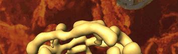
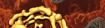
41 Differential Interference Contrast (DIC) The 3T3 cell line is an important fibroblast culture, widely utilized in laboratory research, which was established from disaggregated tissue of an albino Swiss mouse. The fact that 3T3 cells could apparently grow indefinitely, while being unable to instigate tumor growth, helped scientists delineate for the first time the differences between cell mortality and a cell's ability to undergo oncogenic transformation. 41
42 Phase-Contrast and DIC Comparison Phase-Contrast Uses wave nature of light One set of light rays are direct and one set are reflected Makes detailed images of internal structure of living microorganisms possible Image in greyscale DIC Uses differences in refractive indices Uses 2 beams of light Resolution higher Brightly colored image Image appears nearly threedimensional 42
43 Fluorescence Microscopy Advantages of fluorescence Highly sensitive e method Simple implementation Highly sophisticated fluorescent probes (fluorophores) Fluorophores Fluorescent dyes that accumulate in different cellular compartments or are sensitive to ph, ion gradients Fluorescently tagged antibodies to specific cell features Endogenously expressed fluorescent proteins Really endogenous Methods NADH/FAD: enzymes involved in ATP production structural proteins: collagen/elastin amino-acids: tryptophan/tyrosine After gene modification Green fluorescent protein and variants All fluorescence methods can be done (FLIM, FRAP, FRET, TIRF, etc) 43


44 Fluorescence Microscopy Light Path Light source through condenser passes through an excitation filter narrow excitation band Dichroic mirror directs Light excitation to the sample Reflection and fluorescence from the sample pe Dichroic mirror only passes fluorescence Emission Filter emission band Excitation Filter Condenser Lens Eye Ocular Lens Emission Filter Dichroic Mirror Objective Lens Specimen 44
45 Fluorescence Microscopy Dichroic filter: reflects excitation and transmits fluorescence 45
46 Fluorescence Microscopy Common non-laser light sources Arc lamps (Mercury and Xenon) Aligning the light source The epi fluorescence microscope is a reflected light microscope The arc of the lamp imaged at the back focal plane of the objective Ideally just filling the back aperature (Koehler illumination) 46
47 Fluorescence Microscopy Dichroic Mirror Reflects Excitation Band Passes Emission Band Sharp cut-off required Filter selection Broadband filters more excitation, less contrast [more autofluorescence may be excited] Narrowband filters less signal, more contrast Note: eye responds to contrast while detectors respond to signal 47
48 Fluorescence Microscopy Multi-band Imaging g Image (simultaneously or sequentially) the same sample at different excitation emission wavelengths Look at different cell components Example Cell nucleus stained with blue Hoechst dye Mitochondria stained with Mitotracker red Actin cytoskeleton stained with phalloidin derivative conjugated to Alexa 488 (green) 48
49 Limitations of Fluorescence Microscopy Photobleaching Often limits it the number of exposures or the exposure time Photobleaching is the irreversible photochemical destruction of the fluorescent chromophores 49
50 Limitations of Fluorescence Microscopy Autofluorescence Autofluorescence can be present in the images Image at narrow band or use NIR excitation to minimize this effect (NIR exogenous fluorophores) Endogenous Fluorophores amino acids structural proteins enzymes and co-enzymes vitamins lipids porphyrins 50
51 Limitations of Fluorescence Microscopy Resolution is limited in thick specimens Detection of out-of-focus fluorescence The excitation beam illuminates uniformly a wide field of the sample. If the sample is thick, fluorescence will be excited within the focal plane, but also within planes above and below the focus. Some of this fluorescence will be imaged onto the detector and will result in a defocused-looking image Excitation Emission Tissue Human medulla Rabbit Muscle Fibers Pollen Grain 51
52 Limitations of Fluorescence Microscopy Reject out-of-focus light Optical sectioning (next lecture) Create 3d images Confocal Microscopy, Two Photon Microscopy, SIM 52

")
 2")

53 Limitations of Fluorescence Microscopy Resolution is limited by Abbe s law Resolution limit (~ 200 nm) Can you break it? dax = 4 NA 500 nm λn 4 ( ) 2 obj + NA cond α d lat = 1.22 NA 200 nm obj λ + NA cond λ Wavelength Lens 53

 4Pi E r z E1 r z E2 r z S.W. Hell, et al. (1992), Opt. Commun.")
54 4Pi- Microscopy Basic Principles Image from two directions approaching 4pi solid angle Coherent illumination and/or fluorescence detection Interference results in smaller spot size nm (,, ϕ ) = (,, ϕ ) + (,, ϕ ) 4Pi E r z E1 r z E2 r z S.W. Hell, et al. (1992), Opt. Commun. 93,


55 4Pi- Microscopy Z Microtubules, mouse fibroblast Immunofluor, Oregon Green 2 µm 2 µm X Confocal 4Pi 55


56 4Pi- Microscopy Commercial 4Pi-microscope Z- resol < 90 nm (Live cells /aqueous cond.) H. Gugel, et al. (2004), Biophys J 87,
 Measure fluorescence from the remaining excited volume S1 Absorption S0 τ 1 n s Fluorescence Stimulated Emission fl τ vib 1ps S.W. Hell & J.")
57 STED Microscopy 1 st physical concept to break the diffraction barrier in farfield fluorescence microscopy Basic Principles Stimulate the fluorescent dye Cause stimulated emission to de-excite part of the excitation focal volume (doughnut shape) Measure fluorescence from the remaining excited volume S1 Absorption S0 τ 1 n s Fluorescence Stimulated Emission fl τ vib 1ps S.W. Hell & J. Wichmann (1994), Opt. Lett. 19,
58 STED Microscopy y x z x 200 nm Detector y ps 50 ps Depletion (STED) Excitation The stronger the STED beam the narrower the fluorescent spot! S1 Absorption S0 Fluorescence τ 1ns fl Stimulated Emission 1ps S.W. Hell & J. Wichmann (1994), Opt. Lett. 19, 780. τ vib Fluoresc cence I STED [GW/cm 2 ] 58
59 STED Microscopy λ STED = 770 nm STED Focal spot... probed with 1 molecule 48 nm 200nm Confocal 254 nm x [nm] V. Westphal & S.W. Hell (2005), Phys. Rev. Lett. 94,
60 STED Microscopy Imaging 40 nm fluorescence beads: Confocal STED 10 counts/0,3ms counts/0,3ms 89 1µm X Y 60


61 STED Microscopy Confocal STED Heavy subunit of neurofilaments in neuroblastoma G. Donnert, et al. (2006), PNAS 103,
62 STED Microscopy Resolution is not limited by 1.0 the wavelength of light! Resolution just depends on the level of fluorescence depletion. Resolution at the molecular scale is possible with visible light and regular lenses! Resolution follows a new law; a modification of Abbe s law Δx I sat I>>I sat λ 2n sin α 1+ I I sat S.W. Hell (2003), Nature Biotech. 21,


63 The combination: STED-4Pi-Microscopy 8 Monolayer Monolayer confocal STED-4Pi 53 nm M. Dyba, S. W. Hell Fluorescently tagged microtubuli with an axial resolution of nm M. Dyba, S. Jakobs, S.W. Hell (2003), Nature Biotechnol. 21,
 microscopy is the generalized principle of STED microscopy")


64 RESOLFT Microscopy Reversible Saturable (Switchable) Linear Fluorescence Transition (RESOLFT) microscopy is the generalized principle of STED microscopy Same concept as STED but dyes are made to dark state by other mechanisms: switch to triplet state switch to ground state use reversibly photoswitchable dyes Advantages: less powerful lasers need to be used (100 W/cm 2 ) this leads to many more dyes and even fluorescent proteins being used S.W. Hell (2003), Nature Biotechnol. 21,
Imaging Introduction. September 24, 2010
 Imaging Introduction September 24, 2010 What is a microscope? Merriam-Webster: an optical instrument consisting of a lens or combination of lenses for making enlarged images of minute objects; especially:
Microscopy Training & Overview
 Microscopy Training & Overview Product Marketing October 2011 Stephan Briggs - PLE OVERVIEW AND PRESENTATION FLOW Glossary and Important Terms Introduction Timeline Innovation and Advancement Primary Components
Observing Microorganisms through a Microscope LIGHT MICROSCOPY: This type of microscope uses visible light to observe specimens. Compound Light Micros
 PHARMACEUTICAL MICROBIOLOGY JIGAR SHAH INSTITUTE OF PHARMACY NIRMA UNIVERSITY Observing Microorganisms through a Microscope LIGHT MICROSCOPY: This type of microscope uses visible light to observe specimens.
Introduction to Light Microscopy. (Image: T. Wittman, Scripps)
") Introduction to Light Microscopy (Image: T. Wittman, Scripps) The Light Microscope Four centuries of history Vibrant current development One of the most widely used research tools A. Khodjakov et al. Major
Introduction to Light Microscopy (Image: T. Wittman, Scripps) The Light Microscope Four centuries of history Vibrant current development One of the most widely used research tools A. Khodjakov et al. Major
BASICS IN BIOIMAGING AND OPTICS PLATFORM EPFL SV PTBIOP LIGHT MICROSCOPY
 BASICS IN LIGHT MICROSCOPY OVERVIEW 1. Motivation 2. Basic in optics 3. How microscope works 4. Illumination and resolution 5. Microscope optics 6. Contrasting methods -2- MOTIVATION Why do we need microscopy?
microscopy A great online resource Molecular Expressions, a Microscope Primer Partha Roy
 Fundamentals of optical microscopy A great online resource Molecular Expressions, a Microscope Primer http://micro.magnet.fsu.edu/primer/index.html Partha Roy 1 Why microscopy Topics Functions of a microscope
Microscope anatomy, image formation and resolution
 Microscope anatomy, image formation and resolution Ian Dobbie Buy this book for your lab: D.B. Murphy, "Fundamentals of light microscopy and electronic imaging", ISBN 0-471-25391-X Visit these websites:
Reflection! Reflection and Virtual Image!
 1/30/14 Reflection - wave hits non-absorptive surface surface of a smooth water pool - incident vs. reflected wave law of reflection - concept for all electromagnetic waves - wave theory: reflected back
Microscopy Techniques that make it easy to see things this small.
 Microscopy Techniques that make it easy to see things this small. What is a Microscope? An instrument for viewing objects that are too small to be seen easily by the naked eye. Dutch spectacle-makers Hans
VISUAL PHYSICS ONLINE DEPTH STUDY: ELECTRON MICROSCOPES
 VISUAL PHYSICS ONLINE DEPTH STUDY: ELECTRON MICROSCOPES Shortly after the experimental confirmation of the wave properties of the electron, it was suggested that the electron could be used to examine objects
Bio 407. Applied microscopy. Introduction into light microscopy. José María Mateos. Center for Microscopy and Image Analysis
 Center for Microscopy and Image Analysis Bio 407 Applied Introduction into light José María Mateos Fundamentals of light Compound microscope Microscope composed of an objective and an additional lens (eyepiece,
Light Microscopy. Upon completion of this lecture, the student should be able to:
 Light Light microscopy is based on the interaction of light and tissue components and can be used to study tissue features. Upon completion of this lecture, the student should be able to: 1- Explain the
Microscopy: Fundamental Principles and Practical Approaches
 Microscopy: Fundamental Principles and Practical Approaches Simon Atkinson Online Resource: http://micro.magnet.fsu.edu/primer/index.html Book: Murphy, D.B. Fundamentals of Light Microscopy and Electronic
The Compound Microscope. Brightfield: Köhler Illumination
 Outline History of Microscopy The Magnifying Glass The Compound Microscope Brightfield: Köhler Illumination Microscopy µικροσ (mikros): small σκοπειν (skopein): to observe History of Microscopy Well :
Lecture 23 MNS 102: Techniques for Materials and Nano Sciences
 Lecture 23 MNS 102: Techniques for Materials and Nano Sciences Reference: #1 C. R. Brundle, C. A. Evans, S. Wilson, "Encyclopedia of Materials Characterization", Butterworth-Heinemann, Toronto (1992),
INTRODUCTION TO OPTICAL MICROSCOPY
 Experimental Biophysics TEK265, FYST23, TNF060, FAF010F Lab Exercise Supervisor: Karl Adolfsson Written by Peter Jönsson and Jason Beech Updated by Henrik Persson, Karl Adolfsson and Zhen Li karl.adolfsson@ftf.lth.se
Light microscopy BMB 173, Lecture 14, Feb. 21, 2018
 Light microscopy The Structural Biology Continuum Next two lectures: Light microscopy Many slides taken from Scott Fraser, Murphy s Fundamentals of light microscopy, Alberts Molecular Biology of the Cell,
Observing Microorganisms through a Microscope
 2016/2/19 PowerPoint Lecture Presentations prepared by Bradley W. Christian, McLennan Community College CHAPTER 3 Observing Microorganisms through a Microscope 1 Figure 3.2 Microscopes and Magnification.
Compound Light Microscopy. Microscopy. Things to remember... 1/22/2017. This is what we use in the laboratory
 Compound Light Microscopy This is what we use in the laboratory Microscopy Chapter 3 BIO 440 A series of finely ground lenses is used to form a magnified image Specimen is illuminated with visible light
The Nature of Light. Light and Energy
 The Nature of Light Light and Energy - dependent on energy from the sun, directly and indirectly - solar energy intimately associated with existence of life -light absorption: dissipate as heat emitted
Resolution. Diffraction from apertures limits resolution. Rayleigh criterion θ Rayleigh = 1.22 λ/d 1 peak at 2 nd minimum. θ f D
 Microscopy Outline 1. Resolution and Simple Optical Microscope 2. Contrast enhancement: Dark field, Fluorescence (Chelsea & Peter), Phase Contrast, DIC 3. Newer Methods: Scanning Tunneling microscopy (STM),
Very short introduction to light microscopy and digital imaging
 Very short introduction to light microscopy and digital imaging Hernan G. Garcia August 1, 2005 1 Light Microscopy Basics In this section we will briefly describe the basic principles of operation and
Rates of excitation, emission, ISC
 Bi177 Lecture 4 Fluorescence Microscopy Phenomenon of Fluorescence Energy Diagram Rates of excitation, emission, ISC Practical Issues Lighting, Filters More on diffraction Point Spread Functions Thus Far,
Point Spread Function. Confocal Laser Scanning Microscopy. Confocal Aperture. Optical aberrations. Alternative Scanning Microscopy
 Bi177 Lecture 5 Adding the Third Dimension Wide-field Imaging Point Spread Function Deconvolution Confocal Laser Scanning Microscopy Confocal Aperture Optical aberrations Alternative Scanning Microscopy
Education in Microscopy and Digital Imaging
 Contact Us Carl Zeiss Education in Microscopy and Digital Imaging ZEISS Home Products Solutions Support Online Shop ZEISS International ZEISS Campus Home Interactive Tutorials Basic Microscopy Spectral
Final Exam, 150 points PMB 185: Techniques in Light Microscopy
 Final Exam, 150 points Name PMB 185: Techniques in Light Microscopy Point value is in parentheses at the end of each question. Note: GFP = green fluorescent protein ; CFP = cyan fluorescent protein ; YFP
ANSWER KEY Lab 2 (IGB): Bright Field and Fluorescence Optical Microscopy and Sectioning
: Bright Field and Fluorescence Optical Microscopy and Sectioning") Phys598BP Spring 2016 University of Illinois at Urbana-Champaign ANSWER KEY Lab 2 (IGB): Bright Field and Fluorescence Optical Microscopy and Sectioning Location: IGB Core Microscopy Facility Microscope:
Phys598BP Spring 2016 University of Illinois at Urbana-Champaign ANSWER KEY Lab 2 (IGB): Bright Field and Fluorescence Optical Microscopy and Sectioning Location: IGB Core Microscopy Facility Microscope:
CCAM Microscope Objectives
 CCAM Microscope Objectives Things to consider when selecting an objective Magnification Numerical Aperture (NA) resolving power and light intensity of the objective Working Distance distance between the
Biology 29 Cell Structure and Function Spring, 2009 Springer LABORATORY 1: THE LIGHT MICROSCOPE
 Biology 29 Cell Structure and Function Spring, 2009 Springer LABORATORY 1: THE LIGHT MICROSCOPE Prior to lab: 1) Read these instructions (p 1-6) 2) Go through the online tutorial, the microscopy pre-lab
Applications of Optics
 Nicholas J. Giordano www.cengage.com/physics/giordano Chapter 26 Applications of Optics Marilyn Akins, PhD Broome Community College Applications of Optics Many devices are based on the principles of optics
Microscopy. Matti Hotokka Department of Physical Chemistry Åbo Akademi University
 Microscopy Matti Hotokka Department of Physical Chemistry Åbo Akademi University What s coming Anatomy of a microscope Modes of illumination Practicalities Special applications Basic microscope Ocular
Script Bio 407 Applied Microscopy Light microscopy
 Center for Microscopy and Image Analysis Dr. José María Mateos Center for Microscopy and Image Analysis Winterthurerstrasse 190 CH-8057 Zurich Phone 044 635 98 20 mateos@zmb.uzh.ch www.zmb.uzh.ch Script
LSM 510 META in Chang Gung University
 Content LSM 510 META in Chang ung University LSM 510 META 路 理 The features and applications of LSM 510 META 01-09 Introduction of the hardware 10-12 Fluorescence observation in conventional microscope
Invitation for a walk through microscopy. Sebastian Schuchmann Jörg Rösner
 Invitation for a walk through microscopy Sebastian Schuchmann Jörg Rösner joerg.roesner@charite.de Techniques in microscopy Conventional (light) microscopy bright & dark field, phase & interference contrast
PHYSICS. Chapter 35 Lecture FOR SCIENTISTS AND ENGINEERS A STRATEGIC APPROACH 4/E RANDALL D. KNIGHT
 PHYSICS FOR SCIENTISTS AND ENGINEERS A STRATEGIC APPROACH 4/E Chapter 35 Lecture RANDALL D. KNIGHT Chapter 35 Optical Instruments IN THIS CHAPTER, you will learn about some common optical instruments and
ECEN 4606, UNDERGRADUATE OPTICS LAB
 ECEN 4606, UNDERGRADUATE OPTICS LAB Lab 2: Imaging 1 the Telescope Original Version: Prof. McLeod SUMMARY: In this lab you will become familiar with the use of one or more lenses to create images of distant
Development of a High-speed Super-resolution Confocal Scanner
 Development of a High-speed Super-resolution Confocal Scanner Takuya Azuma *1 Takayuki Kei *1 Super-resolution microscopy techniques that overcome the spatial resolution limit of conventional light microscopy
SUBJECT: PHYSICS. Use and Succeed.
 SUBJECT: PHYSICS I hope this collection of questions will help to test your preparation level and useful to recall the concepts in different areas of all the chapters. Use and Succeed. Navaneethakrishnan.V
Introduction to light microscopy
 Center for Microscopy and Image Anaylsis Introduction to light Basic concepts of imaging with light Urs Ziegler ziegler@zmb.uzh.ch Microscopy with light 1 Light interacting with matter Absorbtion Refraction
 Microscopy http://www.microscopyu.com/articles/phasecontrast/phasemicroscopy.html http://micro.magnet.fsu.edu/primer/anatomy/anatomy.html 2005, Dr. Jack Ikeda & Dr. Gail Grabner 9 Nikon Labophot (Question
LlIGHT REVIEW PART 2 DOWNLOAD, PRINT and submit for 100 points
 WRITE ON SCANTRON WITH NUMBER 2 PENCIL DO NOT WRITE ON THIS TEST LlIGHT REVIEW PART 2 DOWNLOAD, PRINT and submit for 100 points Multiple Choice Identify the choice that best completes the statement or
OPTICAL PRINCIPLES OF MICROSCOPY. Interuniversity Course 28 December 2003 Aryeh M. Weiss Bar Ilan University
 OPTICAL PRINCIPLES OF MICROSCOPY Interuniversity Course 28 December 2003 Aryeh M. Weiss Bar Ilan University FOREWORD This slide set was originally presented at the ISM Workshop on Theoretical and Experimental
BIOIMAGING AND OPTICS PLATFORM EPFL SV PTBIOP BASICS IN LIGHT MICROSCOPY
 BASICS IN LIGHT MICROSCOPY INTERNAL COURSE 2014 13 TH JANUARY OVERVIEW 1. Motivation 2. Basic in optics 3. How microscope works 4. Illumination and resolution 5. Microscope optics 6. Contrasting methods
BASICS IN LIGHT MICROSCOPY
 BASICS IN LIGHT MICROSCOPY INTERNAL COURSE 2015 26 TH JANUARY OVERVIEW Light microscopy Why do we need it? How does it work? What are its limitations? What do we need to consider? - 2 - HUMAN EYE Normal
Chapter 25. Optical Instruments
 Chapter 25 Optical Instruments Optical Instruments Analysis generally involves the laws of reflection and refraction Analysis uses the procedures of geometric optics To explain certain phenomena, the wave
Figure 3.4 Approximate size of various types of cells. ~10 um. Red Blood Cells = mm 1500 um. Width of penny Pearson Education, Inc.
 Figure 3.4 Approximate size of various types of cells. ~10 um Red Blood Cells 1.5mm 1500 um Width of penny = 1500 Figure 4.3 The limits of resolution (and some representative objects within those ranges)
Introduction to light microscopy
 Center for Microscopy and Image Anaylsis Introduction to light microscopy Basic concepts of imaging with light Urs Ziegler ziegler@zmb.uzh.ch Light interacting with matter Absorbtion Refraction Diffraction
Heisenberg) relation applied to space and transverse wavevector
 relation applied to space and transverse wavevector") 2. Optical Microscopy 2.1 Principles A microscope is in principle nothing else than a simple lens system for magnifying small objects. The first lens, called the objective, has a short focal length (a
2. Optical Microscopy 2.1 Principles A microscope is in principle nothing else than a simple lens system for magnifying small objects. The first lens, called the objective, has a short focal length (a
Applied Optics. , Physics Department (Room #36-401) , ,
 , ,") Applied Optics Professor, Physics Department (Room #36-401) 2290-0923, 019-539-0923, shsong@hanyang.ac.kr Office Hours Mondays 15:00-16:30, Wednesdays 15:00-16:30 TA (Ph.D. student, Room #36-415) 2290-0921,
Applied Optics Professor, Physics Department (Room #36-401) 2290-0923, 019-539-0923, shsong@hanyang.ac.kr Office Hours Mondays 15:00-16:30, Wednesdays 15:00-16:30 TA (Ph.D. student, Room #36-415) 2290-0921,
R.B.V.R.R. WOMEN S COLLEGE (AUTONOMOUS) Narayanaguda, Hyderabad.
 Narayanaguda, Hyderabad.") R.B.V.R.R. WOMEN S COLLEGE (AUTONOMOUS) Narayanaguda, Hyderabad. DEPARTMENT OF PHYSICS QUESTION BANK FOR SEMESTER III PAPER III OPTICS UNIT I: 1. MATRIX METHODS IN PARAXIAL OPTICS 2. ABERATIONS UNIT II
R.B.V.R.R. WOMEN S COLLEGE (AUTONOMOUS) Narayanaguda, Hyderabad. DEPARTMENT OF PHYSICS QUESTION BANK FOR SEMESTER III PAPER III OPTICS UNIT I: 1. MATRIX METHODS IN PARAXIAL OPTICS 2. ABERATIONS UNIT II
2/4/15. Brightfield Microscopy! It s all about Magnification..! or is it?!
 Brightfield Microscopy It s all about Magnification.. or is it? 1 What actually does go into chosing a microscope Choice depends on what you need the microscope to do. Do you want to magnify stained specimens?
Differential Interference Contrast (DIC) Verses Dark Field and Phase Contrast Microscopy. E. D. Salmon University of North Carolina at Chapel Hill
 Verses Dark Field and Phase Contrast Microscopy. E. D. Salmon University of North Carolina at Chapel Hill") Differential Interference Contrast (DIC) Verses Dark Field and Phase Contrast Microscopy E. D. Salmon University of North Carolina at Chapel Hill How Does Contrast in DIC Differ from Phase and Pol? n e
Differential Interference Contrast (DIC) Verses Dark Field and Phase Contrast Microscopy E. D. Salmon University of North Carolina at Chapel Hill How Does Contrast in DIC Differ from Phase and Pol? n e
Test Review # 8. Physics R: Form TR8.17A. Primary colors of light
 Physics R: Form TR8.17A TEST 8 REVIEW Name Date Period Test Review # 8 Light and Color. Color comes from light, an electromagnetic wave that travels in straight lines in all directions from a light source
Examination, TEN1, in courses SK2500/SK2501, Physics of Biomedical Microscopy,
 KTH Applied Physics Examination, TEN1, in courses SK2500/SK2501, Physics of Biomedical Microscopy, 2009-06-05, 8-13, FB51 Allowed aids: Compendium Imaging Physics (handed out) Compendium Light Microscopy
FLUORESCENCE MICROSCOPY. Matyas Molnar and Dirk Pacholsky
 FLUORESCENCE MICROSCOPY Matyas Molnar and Dirk Pacholsky 1 The human eye perceives app. 400-700 nm; best at around 500 nm (green) Has a general resolution down to150-300 μm (human hair: 40-250 μm) We need
Motorized Axio Observer Start-up instructions
 Start-up instructions 1. If using fluorescence turn on Fluorescent light source. TL light Source (Hal 100) 2. Turn on microscope using switch on lower left side of the microscope. 3. If imaging, turn on
INTRODUCTION THIN LENSES. Introduction. given by the paraxial refraction equation derived last lecture: Thin lenses (19.1) = 1. Double-lens systems
 = 1. Double-lens systems") Chapter 9 OPTICAL INSTRUMENTS Introduction Thin lenses Double-lens systems Aberrations Camera Human eye Compound microscope Summary INTRODUCTION Knowledge of geometrical optics, diffraction and interference,
Chapter 9 OPTICAL INSTRUMENTS Introduction Thin lenses Double-lens systems Aberrations Camera Human eye Compound microscope Summary INTRODUCTION Knowledge of geometrical optics, diffraction and interference,
Confocal Microscopy and Related Techniques
 Confocal Microscopy and Related Techniques Chau-Hwang Lee Associate Research Fellow Research Center for Applied Sciences, Academia Sinica 128 Sec. 2, Academia Rd., Nankang, Taipei 11529, Taiwan E-mail:
Systems Biology. Optical Train, Köhler Illumination
 McGill University Life Sciences Complex Imaging Facility Systems Biology Microscopy Workshop Tuesday December 7 th, 2010 Simple Lenses, Transmitted Light Optical Train, Köhler Illumination What Does a
Katarina Logg, Kristofer Bodvard, Mikael Käll. Dept. of Applied Physics. 12 September Optical Microscopy. Supervisor s signature:...
 Katarina Logg, Kristofer Bodvard, Mikael Käll Dept. of Applied Physics 12 September 2007 O1 Optical Microscopy Name:.. Date:... Supervisor s signature:... Introduction Over the past decades, the number
Basics of Light Microscopy and Metallography
 ENGR45: Introduction to Materials Spring 2012 Laboratory 8 Basics of Light Microscopy and Metallography In this exercise you will: gain familiarity with the proper use of a research-grade light microscope
a) How big will that physical image of the cells be your camera sensor?
 How big will that physical image of the cells be your camera sensor?") 1. Consider a regular wide-field microscope set up with a 60x, NA = 1.4 objective and a monochromatic digital camera with 8 um pixels, properly positioned in the primary image plane. This microscope is
1. Consider a regular wide-field microscope set up with a 60x, NA = 1.4 objective and a monochromatic digital camera with 8 um pixels, properly positioned in the primary image plane. This microscope is
Chapter 1 Parts. Figure 1.1. Parts of a Compound Light Microscope
 Chapter 1 Parts Chapter 1 Parts Figure 1.1 illustrates the parts of an upright compound microscope and indicates the terminology that I use in these notes. Figure 1.1. Parts of a Compound Light Microscope
CCAM s Selection of. Zeiss Microscope Objectives
 CCAM s Selection of Zeiss Microscope Objectives 1. Magnification Image scale 2. Resolution The minimum separation distance between two points that are clearly resolved. The resolution of an objective is
Burton's Microbiology for the Health Sciences
 Burton's Microbiology for the Health Sciences Chapter 2. Viewing the Microbial World Chapter 2 Outline Introduction Using the metric system to express the sizes of microbes Microscopes Simple microscopes
Why and How? Daniel Gitler Dept. of Physiology Ben-Gurion University of the Negev. Microscopy course, Michmoret Dec 2005
 Why and How? Daniel Gitler Dept. of Physiology Ben-Gurion University of the Negev Why use confocal microscopy? Principles of the laser scanning confocal microscope. Image resolution. Manipulating the
Properties of optical instruments. Visual optical systems part 2: focal visual instruments (microscope type)
") Properties of optical instruments Visual optical systems part 2: focal visual instruments (microscope type) Examples of focal visual instruments magnifying glass Eyepieces Measuring microscopes from the
Properties of optical instruments Visual optical systems part 2: focal visual instruments (microscope type) Examples of focal visual instruments magnifying glass Eyepieces Measuring microscopes from the
Chapter Ray and Wave Optics
 109 Chapter Ray and Wave Optics 1. An astronomical telescope has a large aperture to [2002] reduce spherical aberration have high resolution increase span of observation have low dispersion. 2. If two
Chapter 23 Study Questions Name: Class:
 Chapter 23 Study Questions Name: Class: Multiple Choice Identify the letter of the choice that best completes the statement or answers the question. 1. When you look at yourself in a plane mirror, you
Lecture Outline Chapter 27. Physics, 4 th Edition James S. Walker. Copyright 2010 Pearson Education, Inc.
 Lecture Outline Chapter 27 Physics, 4 th Edition James S. Walker Chapter 27 Optical Instruments Units of Chapter 27 The Human Eye and the Camera Lenses in Combination and Corrective Optics The Magnifying
Microscopy. Krishna Priya.K Lecturer Dept. of Microbiology
 Microscopy Krishna Priya.K Lecturer Dept. of Microbiology TERMS AND DEFINITIONS Principle Microscopy is to get a magnified image, in which structures may be resolved which could not be resolved with the
Chapter 2 The Study of Microbial Structure: Microscopy and Specimen Preparation
 Chapter 2 The Study of Microbial Structure: Microscopy and Specimen Preparation 1 Lenses and the Bending of Light light is refracted (bent) when passing from one medium to another refractive index a measure
Chapter 29/30. Wave Fronts and Rays. Refraction of Sound. Dispersion in a Prism. Index of Refraction. Refraction and Lenses
 Chapter 29/30 Refraction and Lenses Refraction Refraction the bending of waves as they pass from one medium into another. Caused by a change in the average speed of light. Analogy A car that drives off
GIST OF THE UNIT BASED ON DIFFERENT CONCEPTS IN THE UNIT (BRIEFLY AS POINT WISE). RAY OPTICS
. RAY OPTICS") 209 GIST OF THE UNIT BASED ON DIFFERENT CONCEPTS IN THE UNIT (BRIEFLY AS POINT WISE). RAY OPTICS Reflection of light: - The bouncing of light back into the same medium from a surface is called reflection
209 GIST OF THE UNIT BASED ON DIFFERENT CONCEPTS IN THE UNIT (BRIEFLY AS POINT WISE). RAY OPTICS Reflection of light: - The bouncing of light back into the same medium from a surface is called reflection
Exam 4. Name: Class: Date: Multiple Choice Identify the choice that best completes the statement or answers the question.
 Name: Class: Date: Exam 4 Multiple Choice Identify the choice that best completes the statement or answers the question. 1. Mirages are a result of which physical phenomena a. interference c. reflection
Microscope. Dr. Leena Barhate Department of Microbiology M.J.College, Jalgaon
 Microscope Dr. Leena Barhate Department of Microbiology M.J.College, Jalgaon Acknowledgement http://www.cerebromente.org.br/n17/histor y/neurons1_i.htm Google Images http://science.howstuffworks.com/lightmicroscope1.htm
INTRODUCTION TO MICROSCOPY. Urs Ziegler THE PROBLEM
 INTRODUCTION TO MICROSCOPY Urs Ziegler ziegler@zmb.uzh.ch THE PROBLEM 1 ORGANISMS ARE LARGE LIGHT AND ELECTRONS: ELECTROMAGNETIC WAVES v = Wavelength ( ) Speed (v) Frequency ( ) Amplitude (A) Propagation
3D light microscopy techniques
 3D light microscopy techniques The image of a point is a 3D feature In-focus image Out-of-focus image The image of a point is not a point Point Spread Function (PSF) 1D imaging 1 1 2! NA = 0.5! NA 2D imaging
Prof. Enrico Gratton - Lecture 6 Fluorescence Microscopy
 Prof. Enrico Gratton - Lecture 6 Fluorescence Microscopy Instrumentation Light Sources: One-photon and Multi-photon Excitation Applications in Cells Lifetime Imaging Figures acknowledgements: E.D. Salmon
EE119 Introduction to Optical Engineering Spring 2003 Final Exam. Name:
 EE119 Introduction to Optical Engineering Spring 2003 Final Exam Name: SID: CLOSED BOOK. THREE 8 1/2 X 11 SHEETS OF NOTES, AND SCIENTIFIC POCKET CALCULATOR PERMITTED. TIME ALLOTTED: 180 MINUTES Fundamental
Introduction. Laboratory Equipment & Supplies. Model 1333PHi Shown (Phase Contrast) (2) Eyepieces (Eyecups installed) Diopter Adjustment Mechanism
 (2) Eyepieces (Eyecups installed) Diopter Adjustment Mechanism") Introduction With the invention of the microscope in the early 17th century, it was made possible to view objects which were too small for the human eye to see. As the microscope evolved, the structure
Introduction With the invention of the microscope in the early 17th century, it was made possible to view objects which were too small for the human eye to see. As the microscope evolved, the structure
Maria Smedh, Centre for Cellular Imaging. Maria Smedh, Centre for Cellular Imaging
 Nonlinear microscopy I: Two-photon fluorescence microscopy Multiphoton Microscopy What is multiphoton imaging? Applications Different imaging modes Advantages/disadvantages Scattering of light in thick
CFIM MICROSCOPY COURSE PROGRAMME PRINCIPLES OF MICROSCOPY CONFOCAL AND FLUORESCENCE MICROSCOPY
 CFIM MICROSCOPY COURSE PROGRAMME PRINCIPLES OF MICROSCOPY 11.01.16-15.01.2016 CONFOCAL AND FLUORESCENCE MICROSCOPY 25.01.16-29.01.2016 PhD Course - University of Copenhagen Department of Biomedical Sciences
Chapter 3 Op,cal Instrumenta,on
 Imaging by an Op,cal System Change in curvature of wavefronts by a thin lens Chapter 3 Op,cal Instrumenta,on 3-1 Stops, Pupils, and Windows 3-4 The Camera 3-5 Simple Magnifiers and Eyepieces 1. Magnifiers
Image Formation. Light from distant things. Geometrical optics. Pinhole camera. Chapter 36
 Light from distant things Chapter 36 We learn about a distant thing from the light it generates or redirects. The lenses in our eyes create images of objects our brains can process. This chapter concerns
30 Lenses. Lenses change the paths of light.
 Lenses change the paths of light. A light ray bends as it enters glass and bends again as it leaves. Light passing through glass of a certain shape can form an image that appears larger, smaller, closer,
Practical Light Microscopy
 Biomedical & X-ray Physics Kjell Carlsson Important: Study the preparatory exercises carefully before the lab session starts! Practical Light Microscopy Laboratory instructions for course SK2500/01, Physics
Advanced Optical Microscopy lecture. 03. December 2012 Kai Wicker
 Advanced Optical Microscopy lecture 03. December 2012 Kai Wicker Today: Optical transfer functions (OTF) and point spread functions (PSF) in incoherent imaging. 1. Quick revision: the incoherent wide-field
Physics 11. Unit 8 Geometric Optics Part 2
 Physics 11 Unit 8 Geometric Optics Part 2 (c) Refraction (i) Introduction: Snell s law Like water waves, when light is traveling from one medium to another, not only does its wavelength, and in turn the
Phys 102 Lecture 21 Optical instruments
 Phys 102 Lecture 21 Optical instruments 1 Today we will... Learn how combinations of lenses form images Thin lens equation & magnification Learn about the compound microscope Eyepiece & objective Total
Name. Light Chapter Summary Cont d. Refraction
 Page 1 of 17 Physics Week 12(Sem. 2) Name Light Chapter Summary Cont d with a smaller index of refraction to a material with a larger index of refraction, the light refracts towards the normal line. Also,
Precision-tracking of individual particles By Fluorescence Photo activation Localization Microscopy(FPALM) Presented by Aung K.
 Presented by Aung K.") Precision-tracking of individual particles By Fluorescence Photo activation Localization Microscopy(FPALM) Presented by Aung K. Soe This FPALM research was done by Assistant Professor Sam Hess, physics
Precision-tracking of individual particles By Fluorescence Photo activation Localization Microscopy(FPALM) Presented by Aung K. Soe This FPALM research was done by Assistant Professor Sam Hess, physics
ABC Math Student Copy. N. May ABC Math Student Copy. Physics Week 13(Sem. 2) Name. Light Chapter Summary Cont d 2
 Name. Light Chapter Summary Cont d 2") Page 1 of 12 Physics Week 13(Sem. 2) Name Light Chapter Summary Cont d 2 Lens Abberation Lenses can have two types of abberation, spherical and chromic. Abberation occurs when the rays forming an image
Page 1 of 12 Physics Week 13(Sem. 2) Name Light Chapter Summary Cont d 2 Lens Abberation Lenses can have two types of abberation, spherical and chromic. Abberation occurs when the rays forming an image
Supplementary Information. Stochastic Optical Reconstruction Microscopy Imaging of Microtubule Arrays in Intact Arabidopsis thaliana Seedling Roots
 Supplementary Information Stochastic Optical Reconstruction Microscopy Imaging of Microtubule Arrays in Intact Arabidopsis thaliana Seedling Roots Bin Dong 1,, Xiaochen Yang 2,, Shaobin Zhu 1, Diane C.
Basics of confocal imaging (part I)
") Basics of confocal imaging (part I) Swiss Institute of Technology (EPFL) Faculty of Life Sciences Head of BIOIMAGING AND OPTICS BIOP arne.seitz@epfl.ch Lateral resolution BioImaging &Optics Platform Light
Basics of confocal imaging (part I) Swiss Institute of Technology (EPFL) Faculty of Life Sciences Head of BIOIMAGING AND OPTICS BIOP arne.seitz@epfl.ch Lateral resolution BioImaging &Optics Platform Light
Chapter 3 Op+cal Instrumenta+on
 Chapter 3 Op+cal Instrumenta+on 3-1 Stops, Pupils, and Windows 3-4 The Camera 3-5 Simple Magnifiers and Eyepieces 3-6 Microscopes 3-7 Telescopes Today (2011-09-22) 1. Magnifiers 2. Camera 3. Resolution
Topic 1 - What is Light? 1. Radiation is the type of energy transfer which does not require... A matter B heat C waves D light
 Grade 8 Unit 1 Test Student Class Topic 1 - What is Light? 1. Radiation is the type of energy transfer which does not require... A matter B heat C waves D light 2. Light-producing technologies, such as
Biomedical Imaging 生物醫學影像學
 Biomedical Imaging 生物醫學影像學 楊自森助理教授 牙體技術學系 2013/02/24 tsyang@tmu.edu.tw 1 Course Outline 1. Course Introduction 2. Basic Optics and Light Microscopes 3. Fluorescence/Confocal/TIRF Microscopes 4. FRET Techniques
PHYSICS FOR THE IB DIPLOMA CAMBRIDGE UNIVERSITY PRESS
 Option C Imaging C Introduction to imaging Learning objectives In this section we discuss the formation of images by lenses and mirrors. We will learn how to construct images graphically as well as algebraically.
Chapter 36. Image Formation
 Chapter 36 Image Formation Image of Formation Images can result when light rays encounter flat or curved surfaces between two media. Images can be formed either by reflection or refraction due to these