Scanning Electron Microscope. Instructions for Use
|
|
|
- Shannon Campbell
- 6 years ago
- Views:
Transcription


1

2 Scanning Electron Microscope Instructions for Use
3 The reproduction, transmission or use of this document or its contents is not permitted without express written authority. Offenders are liable for damages. All rights reserved. We have checked the contents of this manual for agreement with the hardware and software described. Since deviations cannot be precluded entirely, we cannot guarantee full agreement TESCAN, a.s., Brno, Czech Republic
4 VEGA3 SEM Contents Contents Contents Introduction Safety Information Installation and Microscope Repairs Transport and Storage Installation Instructions Fuse Replacement Instrument Repair and the Spare Parts Usage Description of the Microscope Electron Column Electron Column Displaying Modes Electron Column Microscope Centering Centering of the Electron Gun Automatic Centering Manual Centering Chamber and Sample Stage Vacuum Modes High Vacuum Mode Medium Vacuum Mode Low Vacuum Mode Detectors SE Detector LVSTD Detector BSE Detector CL detector Exchange of CL for BSE lightguide Other Detectors Control Elements Keyboard Mouse Trackball Control Panel
5 Contents VEGA3 SEM 8 Getting Started Starting the Microscope Specimen Exchange Images at Low Magnification Imaging of non-conductive samples without coating Images at High Magnification Electron Beam Lithography Stopping the Microscope Microscope Maintenance Basic Microscope Accessories Filament Replacement Starting up the Microscope after a Filament Replacement Mechanical Gun Centering Aperture Change Replacement of the Aperture Holder Insertion of Low Vacuum Aperture Holder Cleaning the Column Types of Contamination or Impurities Cleaning the Column Parts Cleaning the Low Vacuum Aperture The Frequency of Cleaning Specimen Holders
6 VEGA3 SEM Introduction 1 Introduction The VEGA3 series is a family of modern, fully PC-controlled scanning electron microscopes with a tungsten heated filament. Specific Features of the VEGA3 SEM: An innovative and powerful four lens Wide Field Optics design, offering a variety of working and displaying modes. A range of chambers to suit all applications and a wide choice of supplementary accessories. Fast and precise motorized specimen stages. Excellent analytical qualities with optimized ports geometry. Unique live stereoscopic imaging using the 3D Beam technology. Turbomolecular and rotary pumps ensure quick and easy sample exchange and short times to reach a working vacuum. Sophisticated and easy-to-use software for microscope control using a Windows platform. Fully automated microscope set-up. Comprehensive software for image archiving, processing, evaluation and network operations comes as standard. Minimal requirements on space, power supply and environment. Currently the VEGA3 family includes several models of microscope fitted with various chambers according to the user s requirements for chamber size, stage movements precision and/or operation comfort. The abundant control software included in the standard scope of delivery is one of the valued assets of the Vega microscopes. Since the VEGA3 SEM is installed and maintained by trained specialists, technical details and installation procedures are limited to a short overview. In the case of necessary maintenance, reinstallation, hardware changes, etc. the appropriate service authorities or your local supplier have to be contacted for further assistance and instructions. 5
7 Safety Information VEGA3 SEM 2 Safety Information The user is liable to make himself familiar with the care of the device and with the safety rules valid in the country of the user. The microscope works with electric voltages that can be dangerous to life. Any operations with the device which are not mentioned in these instructions, especially the removal of the housing and manipulation of the electric parts of the microscope, may be carried out only by an authorized person. It is also forbidden to substitute a part of the microscope for any other part that is not original and is not delivered by the microscope producer (e.g. the substitution of the original steel blinds on the flanges of the microscope chamber for light alloy blinds can cause an emission of dangerous ionizing radiation!) The microscope is provided with a number of automatic protections making unsuitable usage impossible (e.g. it is not possible to switch on high voltage sources if the specimen chamber or electron gun space are open or are not evacuated to the working vacuum). The deactivation of these protections can cause destruction of the machine and endanger the health of the operating staff. It is strictly forbidden. The symbols used meet the regulation standard ČSN EN , except the symbol: that marks the connectors with high voltage which are not dangerous in the aspect of the mentioned regulation standard (accidental touch can only cause electrical shock). In the documentation there are two types of additional information given: Notes and Warnings, Notes are designated thus: Note: In Italics and Blue print. Warnings are designated thus: WARNING: In Italics and Red print. 6
8 VEGA3 SEM Installation and Microscope Repairs 3 Installation and Microscope Repairs 3.1 Transport and Storage The method of delivery is defined in the contract and is determined individually according to the destination territory. The method of delivery must be approved by the manufacturer. The instrument is delivered partially disassembled and packed. The purchaser is obliged to check the status of the boxes after the delivery company handover. In the case of any damage it is necessary to catalogue the damage and inform the manufacturer of the situation. The packed instrument must be stored in a dry and clean place with a temperature range from -20 C to +40 C and must not be exposed to corrosive substances which can cause oxidation (acid vapours etc.). 3.2 Installation Instructions The microscope is delivered including installation. The installation must be ordered from the seller. The customer shall inform the seller of the readiness of the laboratory for the installation. Once the laboratory is ready, technicians of the manufacturer or technicians of an approved company will carry out the installation, connection to the mains and user training. The customer is not allowed to connect the microscope to the mains or do any other manipulation, except moving the microscope to the storage place. The installation company will fill in the installation protocol. The warranty period will start from this date and the user can start using the instrument normally as described in this manual. 3.3 Fuse Replacement The instrument does not contain any fuses which can be replaced by the user. All fuses are located under the covers which can be removed only by the service technician from the manufacturer or the service technician of an approved company. The fuses can be replaced only by exactly the same type; the type is described in the documentation or on the fuse holder. 3.4 Instrument Repair and the Spare Parts Usage It is only permitted to use original spare parts delivered by the manufacturer. Repair and maintenance which exceed the procedures mentioned in this manual can be performed only by the manufacturer s service technician or a service technician from an approved company. 7
9 Description of the Microscope VEGA3 SEM 4 Description of the Microscope 4.1 Electron Column The scanning electron microscope displays the examined object by means of a thin electron probe. The column forms the electron probe (beam) and sweeps the beam over the examined specimen located in the microscope chamber. The imaging qualities of the microscope depend on the parameters of this electron beam: spot size, aperture angle and beam intensity. The spot size determines the resolution of the microscope as well as usable magnification at stable picture sharpness. It is mainly considered that the spot is circular and has a Gaussian intensity profile. We can specify its size for example with half the width of the intensity distribution. The spot size is determined by the demagnification of the primary electron source, optical aberrations of the final lens (objective) and the diffraction aberration on the final aperture. The spot size is smaller at shorter working distances. The incident electron beam is cone-shaped. The vertex angle of the cone is called the aperture angle. The wider the cone, the lower the depth of focus. The beam intensity (BI) is determined by the number of electrons passing through the probe in a defined time. The image noise of the electron microscope depends on the number of electrons used for the information collected from each picture element. It is necessary to use more time for image scanning at low beam intensity and vice versa. It is evident that the incident beam parameters influence each other. The optical system of the microscope allows operation in different modes when some parameters of the beam can be preferred and the others can be kept down. Here are some typical examples: Work at high magnification. It is necessary to reach a high resolution, therefore low beam intensity, short working distance and slow scanning speed should be used. We recommend choosing RESOLUTION mode, working distance not more than 7 mm and scanning speed 7 or slower. See chapter Work with high intensity. The spot size and the aperture angle are big; resolution is small. Useful magnification is low but fast scanning can be used because the signal to noise ratio is better. The higher the BI index, the higher the intensity. Work with high depth of focus. The aperture angle must be small. Use DEPTH mode. The column of the microscope consists of the following main parts: The electron gun is a source of accelerated electrons. It consists of a cathode, Wehnelt cylinder and anode. The cathode and Wehnelt cylinder are connected to the negative electric potential; the anode and the remaining part of the column are on the earth potential. The cathode is a tungsten filament, heated to such a high temperature that it causes emission of free electrons. The voltage between the Wehnelt cylinder and the anode determines the accelerating voltage of electrons and thus their energy. The electron flow from the gun is specified with the emission current. The emission current can be changed by applying a negative potential between the Wehnelt cylinder and the cathode (bias). The whole gun system works as a virtual source of electrons with the following specifications: a (25 50) µm dimension, electron energy from 200 ev up to 30 kev, emission current of up to 300 µa and brightness of 10 6 A/cm 2 sr. 8


10 VEGA3 SEM Description of the Microscope The VEGA3 SEM cross-section and schematic representation of its optical elements: The gun centering is formed by a system of electromagnetic deflection coils under the gun. It is designed for the tilting of the electron beam emitted from the gun so that it enters the axis of the optical system of the column. It is controlled by the function gun alignment. The gun is correctly centered if the most intensive part of the electron beam is selected and the brightness of the image is the highest. The spray aperture is placed under the centering coils of the gun. It is intended for retaining the marginal parts of the electron beam emitted by the gun. The pair of condensers C1 and C2 are strong magnetic lenses for the demagnification of the virtual source. The higher the excitation of the condenser, the shorter its focal length and the higher its demagnification. 9
11 Description of the Microscope VEGA3 SEM The final aperture cuts the size of the final incident beam. It is placed in the holder at the end of the central vacuum pipe of the column, about 60 mm under condenser C2. The optimum size of the aperture hole is 50 µm. The auxiliary lens IML (Intermediate Lens) is a magnetic lens used for the aperture change of the beam entering the lens OBJ or for displaying if the OBJ is off. The change of the IML excitation causes the shifting of the electron beam across the optical axis and therefore it is necessary to compensate this shifting by means of the centering coils IML Centering. The Stigmator is an electromagnetic octupole. It is intended to compensate for astigmatism in all displaying modes. The scanning coils are formed by two stages of the deflection coils. A scanning ramp is connected to the coils. The ramp frequency determines the scanning speed of the electron beam; the amplitude determines the microscope's field of view and the magnification. The objective OBJ is the last magnetic lens of the column that forms the resulting electron beam. In the usual modes the excitation of the OBJ is determined by the working distance - the distance between the lower objective pole piece and the focused specimen surface. 10

12 VEGA3 SEM Description of the Microscope Electron Column Displaying Modes RESOLUTION Mode This is the basic and most common displaying mode. The IML lens is switched off, the OBJ lens is excited and it focuses the final electron beam. Characteristics: high resolution low depth of focus In this mode, the VEGA3 works like other common three lens microscopes without IML lens. The aperture is nearly optimal for lower BI values (small spot size, low beam current), short working distances (4-5) mm and for the accelerating voltage 30 kv. The pivot point of the scanning and the electric image shifts are close to the principal plane of the objective OBJ, so that the curvature of the field, distortion and field of view are as good as possible. The centering of the objective OBJ is performed by defined beam tilt of the central electron beam, which does not cause image shift. This mode is intended for displaying with the highest resolution. 11

13 Description of the Microscope VEGA3 SEM DEPTH Mode The DEPTH mode differs from the previous mode by the auxiliary lens IML being switched on. Characteristics: good resolution increased depth of focus The aperture of the final beam is lower, but the spot size is bigger in comparison with RESOLUTION mode. The beam in the probe stays unchanged. This mode is used if it is necessary to have a greater depth of focus. 12

14 VEGA3 SEM Description of the Microscope FIELD Mode The FIELD mode utilizes the intermediate lens IML for the electron beam focusing while the objective OBJ is off. Characteristics: large field of view high depth of focus worse resolution The beam aperture is very small and the depth of focus is usually higher than the field of view. As the objective OBJ is off in this case, it does not affect the middle beam and thus does not need to pass near the centre of the objective OBJ. The position of the pivot point of scanning is optimized according to the field of view. The centering coils IML center the supplemental intermediate lens IML to avoid image movement during focusing. The DC component of the scanning coils is set up so that no image shift occurs if switched from RESOLUTION mode to FIELD mode. The characteristic of this mode is a bigger spot size. The maximum magnification used is therefore a few thousand. The mode is used for the searching of the parts of the specimen to be examined. 13


15 Description of the Microscope VEGA3 SEM WIDE FIELD Mode The WIDE FIELD mode uses the intermediate lens IML for focusing the electron beam, while the objective OBJ is excited to a high value. Characteristics: extra large field of view image distortion is corrected and minimized Highly excited objective multiplies the deflection of the beam. The aperture of the beam is very small and the depth of focus is very high. The IML Centering coil serves for minimizing the image shift when focusing. The mode is used to search for the part of the specimen to be examined. To know the proper magnification value, the objective must be well focused. This might be a little difficult due to the high depth of focus. 14

16 VEGA3 SEM Description of the Microscope CHANNELING Mode In CHANNELING mode, the scanning and lens focusing is controlled so that the electron beam touches the same point of the specimen surface all the time. By means of scanning the beam, only the angle of incidence of the electron beam is changed. Characteristics: the position of the specified point in the image depends on the beam tilt it is the mode for ECP acquisition - Electron Channeling Pattern The resulting image is the amount of electrons dependent on the impacting beam angle. The excitation ratio of the scanning coils is set up so that the beam utilizes the whole area of the objective lens bore and enters the lens parallel to the optical axis. All electron beams parallel to the optic axis are focused by the lens into a single point on the specimen surface. As a consequence, the scanning is transformed into beam tilting, i.e. the resulting pivot point of the scanning lies on the specimen surface plane. The intermediate lens focuses the beam into the upper focal point of the objective lens. The result is that the beam, after passing through the objective lens, is parallel and the angular resolution of ECP (Electron Channeling Pattern) images is at its maximum. The mode is intended for the examination of crystallographic materials. The minimum size of crystals should be 150 µm. Note: ECP patterns are produced by back scattered electrons, it is preferable to use a BSE detector for imaging if available. 15
17 Description of the Microscope VEGA3 SEM Electron Column Microscope Centering It is necessary to centre the electron optics of the column to reach high quality images. The goal is to ensure that the beam is as close as possible to the optical axis of the column and thus minimize optical aberrations. The centering is electronic; it is fully controlled by the PC. It is necessary to adjust every displaying mode and every high voltage range you intend to use. The whole HV range from 200 V up to 30 kv is divided into four HV indices (200 V - 5 kv, 5 kv - 10 kv, 10 kv - 20 kv, 20 kv - 30 kv). This means that once you work in RESOLUTION mode and you work at 10 kv and 30 kv, it is necessary to centre the microscope for 10 kv as well as for 30 kv. With further switching among HV indices the VegaTC software remembers all settings, so the user does not need to carry out any further centering. Each microscope is factory centered at 5 kv, 10 kv, 20 kv and 30 kv and this setup is loaded for standard user s accounts (guest, supervisor). Note: Every user can save his own configurations in menu Options -> Configurations Save As. Using of various configurations can save user s time when switching between various voltages within the same HV index. Recommended centering conditions The centering is done by means of a special centering specimen, which is included in the microscope accessories and is marked as ADJ. The surface of this specimen has a fine structure, making the centering easier. If this specimen is not available, it is possible to use a common specimen stub. Once you start centering, the image must be focused perfectly. Mode Working Distance (WD) Beam Intensity (BI) Magnification (Mag) RESOLUTION (10 15) mm 11 ( )x DEPTH (10 15) mm x FIELD (10 15) mm x WIDE FIELD (10 15) mm 11 max. Mag It is possible to do the centering either automatically, or manually. Manual centering is suitable for situations where it is necessary to set up special working conditions Centering of the Electron Gun The centering is done by automatic procedure. It is always necessary to perform this auto centering after high voltage value changes inside a specified range with the item High Voltage in the Pad panel. 1. Insert the centering specimen. 2. Set up the recommended working conditions in RESOLUTION mode. Focus the image and set up minimum magnification. 3. Use the Adjustment >>> Auto Gun Centering function in the Electron Beam panel (Figure 1). 16

18 VEGA3 SEM Description of the Microscope Figure Automatic Centering The automatic procedure of column centering is very fast and suitable for low magnifications. For very precise work at high magnifications manual centering is more suitable. 1. Insert the centering specimen. 2. Set up the recommended working conditions and focus the image in RESOLUTION mode. 3. Use the Adjustment >>> Auto Column Centering function in the Electron Beam panel (see Figure 1) Manual Centering 1. Insert the centering specimen. 2. Set up the recommended working conditions and focus the image in RESOLUTION mode. Note: Manual centering is for experienced users and it is necessary to perform it individually for each from four HV indexes and keep to described sequence for each procedure. The RESOLUTION mode must always be adjusted first. Note: If working at a higher magnification and precise centering is needed, the manual centering procedure should first be done at a lower magnification and repeated more precisely at higher magnification. RESOLUTION mode 1. Use the Adjustment >>> Manual Column Centering function in the Electron Beam panel. Press the Next>> button. The image starts wobbling, that is, periodically changing the working distance. 2. Minimize the image movement by changing the OBJ Centering using the trackball and keys F11 and F12. Press the Finish button. DEPTH mode 1. Set the same magnification for both RESOLUTION and DEPTH modes. Use the Adjustment >>> Manual Column Centering function. Press the Next>> button. 2. Adjust the IML Centering parameters so that the image is the same as in RESOLUTION mode. Use the trackball and keys F11 and F12. Press the Next>> button. 3. Minimize the image movement by means of changing the OBJ Centering. Press the Finish button. 17
19 Description of the Microscope VEGA3 SEM FIELD mode 1. Set the same magnification for RESOLUTION and FIELD modes. Use the Adjustment >>> Manual Column Centering function again. Press the Next>> button. 2. Minimize the image movement by means of changing the IML Centering parameters using the trackball and keys F11 and F12. Press the Next>> button. 3. Adjust the OBJ Centering parameters so that the image is the same as in RESOLUTION mode. Use the trackball and keys F11 and F12. Press the Finish button. WIDE FIELD mode 1. Set the same magnification for RESOLUTION and WIDE FIELD modes. Use the Adjustment >>> Manual Column Centering function and the Next>> button. 2. Adjust the IML Centering parameters so that the image is the same as in RESOLUTION mode. Press the Finish button. 4.2 Chamber and Sample Stage The chamber is a sealed space under the column where specimens are placed for examination. The specimen is fixed on the sample stage which allows movement of the sample during the examination process. The chamber must be evacuated during examination. The sample stages are divided into two basic types: motorized manual Manipulators have electrically isolated specimen holders. The specimen holder is connected to a pa-meter. The pa-meter also works as an acoustic contact indicator of the specimen to the chamber. If contact between the specimen holder and the chamber body occurs, all motorized axes will stop and an audible sound will indicate the contact (touch alarm). The chamber and sample stage types: Type Motorized axes Manual axes Eucentricity SB X, Y, Rotation Z, Tilt LM X, Y, Z, Rotation, Tilt automatic XM X, Y, Z, Rotation, Tilt automatic GM X, Y, Z, Rotation, Tilt automatic The eucentric position is such a position of the specimen that the observed area of the sample does not move when the sample itself is tilted. For the motorized stages the autoeucentric function can be activated by checking the box Keep view field in the Stage Control panel in the VegaTC software. 18

20 VEGA3 SEM Vacuum Modes 5 Vacuum Modes The microscope allows the investigation of specimens in a pressure range of Pa to 2000 Pa. It is necessary to use medium or low vacuum mode to investigate nonconductive samples. Mode Pressure [Pa] Microscope type Note high vacuum SBH, LMH, XMH, GMH, SBU, LMU, XMU, GMU medium vacuum SBU, LMU, XMU, GMU low vacuum SBU, LMU, XMU extended low vacuum LMU, XMU 1x rotary pump aperture in the objective 2x rotary pump aperture in the objective Configuration of the apertures in the electron column High and medium vacuum mode Low vacuum mode 19
21 Vacuum Modes VEGA3 SEM High and medium vacuum modes: the upper spray aperture (500 µm) is located just below the C2 condenser and the final aperture diaphragm (50 µm) at the end of the central vacuum tube approximately in the middle of the IML lens (see chapter 4.1). Both apertures are located in the one aperture holder which is inserted in the central vacuum tube all the way down to the mechanical stop. The microscope is delivered with this aperture holder inside the microscope column. Low and extended low vacuum modes: the same aperture holder is used as for high and medium vacuum modes, but only the 500 µm spray aperture is used, which is located just below the C2 condenser (the same as with high and medium vacuum modes). The aperture diaphragm (75 µm) is located in the special low vacuum aperture holder, which is then inserted into the objective. Note: The microscope is delivered configured for high and medium vacuum mode. The aperture holder for low and extended low vacuum mode is part of the microscope accessories (see chapter 9.1). 5.1 High Vacuum Mode In high vacuum mode, it is possible to investigate both conductive and non-conductive samples; however non-conductive samples require previous metal coating (Cr, Au, Au-Pd, Pt). All displaying modes are available. 5.2 Medium Vacuum Mode In medium vacuum mode - up to 150 Pa, it is possible to examine samples using all displaying modes, because the differential pumping aperture is located in the upper position. Instructions: 1. Press the UniVac button in the Low Vacuum Mode panel (see Figure 11; chapter 8.4). Only SBU models: Close the manual valve, which divides the specimen chamber and the pumping line. The valve can be closed by turning the handle clockwise and pushing it towards the specimen chamber. 2. Enter the desired chamber pressure value in the field next to the UniVac button and click on the OK button. 3. To return to high vacuum mode, press the UniVac button again. Only SBU models: Open the dividing valve manually. 5.3 Low Vacuum Mode In low vacuum mode - up to 500 Pa (up to 2000 Pa, if the microscope is equipped with a secondary rotary pump), it is possible to examine samples using only RESOLUTION and DEPTH modes, because the differential pumping aperture is located in the lower position. Instructions: 1. Take out the final aperture diaphragm (50 µm) (see chapter and 9.6.2). 2. Put the low vacuum aperture (75 μm) into the objective and change the aperture holder according to the description in chapter Confirm the aperture replacement in the menu SEM -> Change UNI mode. 20
22 VEGA3 SEM Vacuum Modes 4. Pump the microscope. 5. Switch the microscope to low vacuum mode (pressure range 3 Pa Pa) using the UniVac button in the Low Vacuum Mode panel. Only SBU models: Close the manual valve dividing the specimen chamber and the pumping line. The valve can be closed by turning the handle clockwise and pushing it towards the specimen chamber. 6. Enter the requested pressure value in the field next to the UniVac button and click on the OK button. 7. To return to high vacuum mode, press the UniVac button and open the manual valve. 8. If it is necessary to use the microscope in all working modes, remove the aperture from the objective and replace the final aperture. It is also necessary to confirm the replacement of the final apertures in the menu SEM -> Change UNI mode. 21
23 Detectors VEGA3 SEM 6 Detectors The detection system may contain a set of detectors designed for detecting various signals resulting from electron beam interaction with the sample surface. The microscope is always delivered with the SE detector. Switching on In the case of adjustment of the required detector, select the appropriate one from the list box in the SEM Detectors & Mixer panel (see Figure 3 in chapter 8.3). This procedure is valid for all detectors except the LVSTD, where further procedures are needed (see chapter 6.2). 6.1 SE Detector The detector works in high vacuum only. Secondary electrons enhance topographic contrast contrary to material contrast of backscattered electrons. The secondary electron (SE) detector is a basic standard detector always present in the microscope. The SE detector is of an Everhart-Thornley type. The grid on the front part of the detector has positive potential. This attracts and accelerates the low-energy secondary electrons arising on the specimen surface and focuses them onto the scintillator. The light flashes, which result from the impingement of the electrons on the scintillator, are transferred through the light guide to the photo-multiplier outside the chamber of the microscope. 6.2 LVSTD Detector The detector works in low vacuum only. The LVSTD detector (Low Vacuum Secondary Tescan Detector) is a detector of secondary electrons, specially designed for low vacuum mode. It is suitable for the investigation of non-conductive samples. The LVSTD consists of a standard Everhart-Thornley detector situated in a separated detector chamber. This detector chamber is pumped by a small turbomolecular pump. Switching on Check if UniVac mode is switched on and check if the required value of the pressure in the chamber has been set lower than ~500 Pa. If not, set the pressure in the panel to a value lower than 500 Pa.
24 VEGA3 SEM Detectors 2. To switch on the detector click on the LVSTD button in the Low Vacuum Mode panel (see Figure 12; chapter 8.4). 3. Now the detector chamber is automatically pumped down. This may take about 2 minutes. The blinking message "LVSTD detector not ready yet" appears in the panel. Wait until this message disappears. 4. In the SEM Detectors & Mixer panel select LVSTD detector from the list box (Figure 3). Switching off The detector can be switched off by simply clicking on the LVSTD button in the Low Vacuum Mode panel. The detector is automatically switched off: if the pressure in the chamber exceeds value higher than 500 Pa. if UniVac mode is switched off. The detector needs to be switched on manually if automatic detector switch-off occurs. Note: The stability of the signal from the LVSTD depends strongly on the pressure inside the chamber. In order to obtain an image with stable brightness, it is necessary to have stable pressure in the chamber. Therefore, after a change of the required pressure value, it might be necessary to wait a while until the pressure reaches the new level and becomes stable. Note: The secondary electrons, in contrast with backscattered electrons, are much more sensitive to specimen surface charging, as they are of very low energy. There are several ways how to eliminate charging: using a higher pressure in the chamber, using a lower accelerating voltage of primary electrons or using lower electron beam current. 6.3 BSE Detector The detector works in high and low vacuum. Back-scattered electrons (BSE) enhance material contrast of the sample. The BSE detector is of the scintillation type. An annular (YAG) mono-crystal scintillator with a conductive surface is placed in the optical axis directly under the lower pole extension of the objective. The high energy back-scattered electrons impinge the scintillator without any additional acceleration and excite the scintillator atoms that emit visible radiation photons successively. The photons are carried, by means of the light guide, through the side outlet of the scintillator to the cathode of the photo-multiplier. They are then processed in the same way as the signal coming from the secondary electrons. The BSE detector is manufactured in an R-BSE (Retractable BSE) version. This modification allows the retraction of the detector from under the pole piece position if the detector is not used. This enables the specimens to be moved as close as possible to the objective when viewed by other detectors. 6.4 CL detector The detector works in high as well as low vacuum. The cathodoluminescence detector is available in two versions depending on the wavelength range of the detected light: 350 nm 650 nm range (mainly visible and near UV light) or ( ) nm range (UV, visible and near IR light). The first version is made either as a stand-alone detector or exchange CL/BSE detector. The IR camera (Chamber View) must be switched off during operation of the CL detector. 23
. 2.")


25 Detectors VEGA3 SEM Exchange of CL for BSE lightguide (Only available in exchange CL/BSE of ( ) nm range version) 1. Fully retract the current detector (i.e. it is close to the chamber wall, not under the column). 2. Put on gloves and open the chamber. Rotate the light guide by hand around its axis by about 30 degrees. 3. Move the current lightguide horizontally in the direction of its axis towards the objective until it is released. 4. Insert the new lightguide in exactly the opposite way: rotated by about 30 degrees from its working position, move it in the direction of its axis horizontally towards the photomultiplier until the stop. 5. Rotate the new lightguide by hand to its fixed position. 6. Return the detector carefully to its working position using the retraction mechanism and observe whether the new lightguide sits well and does not hit the objective. 6.5 Other Detectors TESCAN provides other special detectors which can be attached to the microscope. It is possible to obtain the list from the manufacturer. 24
26 VEGA3 SEM Control Elements 7 Control Elements 7.1 Keyboard The keyboard is used for text and numeric input. Its usage does not differ from the system Windows practice. Keyboard shortcut Ctrl + O Ctrl + S Ctrl + P Alt + X Ctrl + H Ctrl + C Ctrl + V Ctrl + Alt + PgUp Ctrl + Alt + PgDn Ctrl + PgUp Ctrl + PgDn F1 F11 hold down F12 hold down Command Open... Save As... Print... Exit View Header... Copy to Clipboard... Paste from Clipboard... Zoom All In Zoom All Out Zoom In Zoom Out Help - Contents Blocks the changing of the right parameter of the active function. Blocks the changing of the left parameter of the active function. 7.2 Mouse The mouse usage follows the Windows system practice. Mouse functions during normal scanning: Double-clicking with the left mouse button on the SEM Scanning window switches the Focus window on/off. Turning the mouse wheel changes the scan speed (the SEM Scanning window needs to be active). If the microscope is scanning over the whole SEM Scanning window, then o clicking the right mouse button opens the context menu for simple program control. If the microscope is scanning only in the Focus window, then o holding down the right mouse button and dragging the mouse cursor in the SEM Scanning window changes the dimensions of the Focus window. 25


27 Control Elements VEGA3 SEM o o o holding down the left mouse button and dragging the mouse cursor in the SEM Scanning window moves the Focus window. double-clicking the right mouse button on the Focus window moves this window to the centre of the image. clicking the right mouse button out of the Focus window opens the context menu. Clicking the mouse wheel on a selected object in the SEM Scanning window moves the stage so that the object lies in the centre of the SEM Scanning window. Holding down the mouse wheel on a selected object and dragging the cursor to any position in the SEM Scanning window moves the object to the selected position in the SEM Scanning window. Holding down the mouse wheel on a selected object in the SEM Scanning window for longer than 0.8 seconds moves the stage so that the object lies in the centre of the SEM Scanning window and the magnification is increased by the factor set in the SEM -> Options -> Center Zoom. Note: If an additional software module is active, the functions of the buttons can be different. 7.3 Trackball The trackball is often used with the Pad panel. Turning the trackball in the direction of the axis X changes the first parameter of the active function; turning the trackball in the direction of the axis Y changes the second parameter of the active function. Holding the F11 key locks the first parameter of the active function; using the F12 key locks the second parameter of the active function. 7.4 Control Panel The Control Panel has several knobs and a colour touch screen. It was developed by TESCAN exclusively for SEM control. It is not a standard SEM part. The manual knob set provides the user with a simple and straightforward way of operating the microscope. It can control the stage, magnification, focus, beam intensity, scanning speed and other parameters. Most common functions have dedicated knobs. The three upper knobs have variable function; their actual function is shown at the bottom of the touch screen. Several important parameters are shown in the middle of the display. There are also shortcuts to the automatic functions (focus, brightness/contrast, image acquisition) in the header. 26
28 VEGA3 SEM Getting Started 8 Getting Started 8.1 Starting the Microscope 1. Turn the main switch key to the right (ON position). Wait for the computer to boot. 2. Click on the VegaTC icon on the Windows desktop. The VegaTC - Log in screen is displayed prompting for user name and password. 3. After logging in, the latest configuration will be loaded from the user profile. If a new user profile is created, load the supervisor configuration using Configurations Load function from the Options menu. 8.2 Specimen Exchange The specimen should somehow be fixed or glued to the specimen stub before it is inserted into the chamber. It is possible to use 12.5 mm specimen stubs or any other specimen holders, delivered as microscope accessories (see chapter 9.7). If the specimen is examined in high vacuum mode, it must be conductive or must be made conductive using one of the methods described in the technical information. The conductive surface of the specimen must be conductive contacted to the stub. Non-conductive samples can be investigated in low vacuum mode. Instructions: 1. Vent the microscope by using the VENT button in the Vacuum panel. Wait until the pressure is at atmospheric level. 2. Set the tilt of the specimen stage to zero. 3. Open the chamber door by gently pulling it. 4. The automatic positions set up in the Stage Control panel can be used, which are intended for specimen position exchange. To select the sample position click on the appropriate number button on the carousel. At this time the button background is red to indicate the specimen exchange mode. WARNING: If the specimen stage is moving, do not touch any of its parts. The moving manipulator can cause health injuries. During the changing of the specimen use the suitable gloves for prevention of pollution of inner microscope parts. 5. Loosen the screw holding the specimen stub on the specimen stage. Remove the specimen stub by lifting the stub upwards. It is recommended that suitable tweezers be used. 6. Use the previous steps in reverse order to place a new specimen in position. Once the specimen stub is fastened with the specimen, make sure that it will not touch any interior part of the chamber. Contact between the specimen and the chamber will be indicated by an acoustic buzzer. WARNING: Before closing the chamber, make sure that the specimen inside does not touch the chamber, objective pole piece or any of the detectors. Collision of the specimen with any of the parts of the chamber interior can cause damage to the microscope. 27

, one for each HV index.")
.")
29 Getting Started VEGA3 SEM Note: Contact between the specimen and any part of the chamber is indicated by a special electric circuit. This circuit is based on measuring the electric current. It works only if the specimen is conductive. 7. Close the chamber door by pushing it towards the chamber. 8. Start the pumping procedure by clicking on the PUMP button in the Vacuum panel, where the actual pressure and pumping progress are also displayed. Check that the chamber door is tightly closed. 8.3 Images at Low Magnification There are four factory presets for the accelerating voltage (5 kv, 10 kv, 20 kv, 30 kv), one for each HV index. The user does not need to make any further adjustments by switching among them and using magnification up to 4000x. 1. Click on the PUMP button in the Vacuum panel to start the pumping procedure (Figure 2). It usually takes around 3 minutes to reach vacuum ready - status which means that the microscope is ready to use. If there is a need to exchange the specimen, follow the instructions in chapter 8.2. Figure 2 2. In the SEM Detectors & Mixer panel select the appropriate detector from the list box (Figure 3). We recommend using the SE or BSE detector. When the BSE detector is used, make sure that the detector is not retracted! See chapter 6 for detailed information. Figure 3 Note: Note the difference between SE and BSE images below (Figure 4). 3. Select the accelerating voltage (30 kv recommended) using the combo box in the Electron Beam panel (Figure 5). 4. Clicking on the HV button in the Electron Beam panel turns the high voltage on and starts the heating of the tungsten filament (see Figure 5) Right-click in the SEM Scanning window to open the menu and select the Minimum Magnification function (Figure 6).


. Note: If the SEM Scanning window")

.")
30 VEGA3 SEM Getting Started Figure 4 SE Detector BSE Detector Figure 5 6. Right-click in the SEM Scanning window to select the Auto Signal function to set brightness and contrast (see Figure 6). Note: If the SEM Scanning window remains black, select the Auto Gun Heating function using the combo box in the Electron Beam panel after clicking on the Adjustment >>> button (Figure 7). Figure 6 29
 and select RESOLUTION or use the Continual Wide Field option switches automatically between WIDE FIELD and")
31 Getting Started VEGA3 SEM Figure 7 7. Select RESOLUTION mode (click on the Scan Mode function in the Info Panel (see Figure 10) and select RESOLUTION or use the Continual Wide Field option switches automatically between WIDE FIELD and RESOLUTION mode and vice versa when increasing or decreasing magnification). 8. Focus the image by clicking on the WD icon in the Toolbar and turning the Trackball from left to right (or vice versa). Alternatively use the Auto WD function for focusing (see Figure 6). Double-clicking (left mouse button) in the SEM Scanning window opens the Focus window. To remove the Focus window double-click anywhere in the SEM Scanning window. 9. To select beam intensity (BI 10 recommended), first left-click on the BI icon on the Toolbar and then use the arrows in the Pad panel (Figure 8). Figure To select the sample position in the Stage Control panel, click on the appropriate number button on the carousel (Figure 9) or use the manual knobs in the case of the SB microscope type. 11. Placing the cursor over the SEM Scanning window and clicking the mouse wheel moves that area on the stage into the centre of the image. See chapter 7.2 for other mouse actions. 12. To magnify the image click on the Magnification icon on the Toolbar and turn the Trackball from left to right. 13. Once the area of interest is magnified and focused as desired, right-click on the Speed icon on the Toolbar and select the appropriate scanning speed. 14. Clicking on the Acquire button in the Info Panel (Figure 10) or on the icon on the Toolbar saves the image. Fill in the note, sign and description field 30

32 VEGA3 SEM Getting Started Figure 9 if necessary. Choose a folder in which to store the image. To change the parameters of the image use the Image Parameters function in the main SEM menu. Figure 10 31
, therefore Tescan has developed the LVSTD detector which gives")
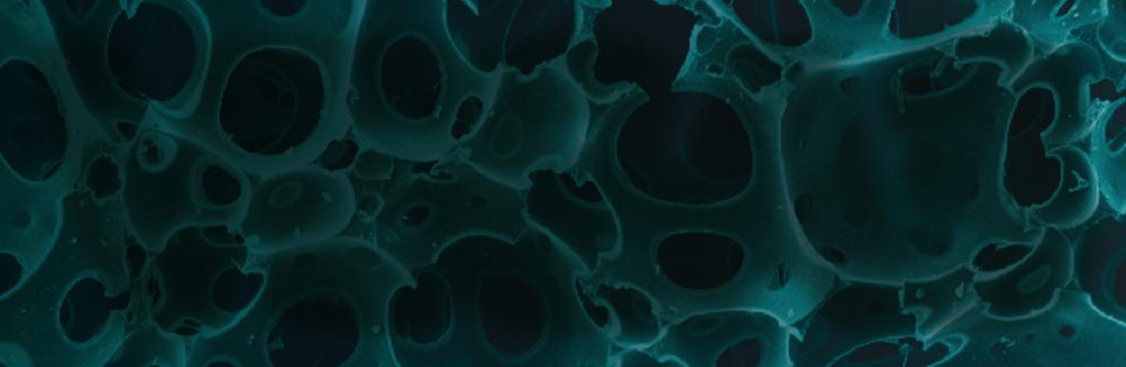
33 Getting Started VEGA3 SEM 15. Clicking on the icon opens the dialogue for saving the actual adjustment of the microscope. It is possible to restore the saved adjustment of the microscope later. 8.4 Imaging of non-conductive samples without coating An ordinary SE detector is not available in low vacuum operations (see chapter 6), therefore Tescan has developed the LVSTD detector which gives topographical information from the sample in low vacuum. The BSE detector is available for both modes (LowVac, HiVac) and gives compositional information. The procedure is different for medium vacuum mode and low vacuum mode. Medium/Low vacuum mode (pressure range 3 Pa Pa/3 Pa 2000 Pa): 1. Click on the UniVac button in the Low Vacuum Mode panel (Figure 11) to switching the microscope to medium vacuum mode (pressure range 3 Pa Pa) (see chapter 5.2). All scan modes will be enabled. For low vacuum mode (pressure range 3 Pa Pa) is needed follow the steps in chapter Switch on the LVSTD detector by clicking on the LVSTD button in the Low Vacuum Mode panel (see Figure 12). This button is present if the LVSTD detector is attached to the chamber. Figure 11 Figure To switch between detectors use the SEM Detectors & Mixer panel and select the appropriate detector (BSE or LVSTD) from the list box (see Figure 3). 4. Turn on high voltage by clicking on the HV button in the Electron Beam panel (see Figure 5). 5. Set minimum magnification. 6. To select beam intensity (BI 10 recommended), first left-click the BI icon and then use the arrows in the Pad panel (Figure 8). 7. Use the Auto Signal function to set suitable brightness and contrast. 32
 and turn the Trackball to set the brightest area into the centre of the SEM Scanning window. 9.")
.")
. 2. Select the fourth HV index using the combo box in the Electron Beam panel (20 kv - 30")
34 VEGA3 SEM Getting Started 8. Select the OBJ Centering function from the combo box in the Pad panel (Figure 13) and turn the Trackball to set the brightest area into the centre of the SEM Scanning window. 9. Follow the instructions in chapter 8.3. Note: Some non-conductive samples, which are not too sensitive to the beam, can be handled at lower voltages in high vacuum mode. Different high voltages can be selected from the Electron Beam panel. Note: See LVSTD images obtained at low vacuum mode of an organic sample without coating (Figure 14). Figure 13 Figure Images at High Magnification The best resolution is achieved at the highest accelerating voltage (30 kv) of the primary electrons. 1. Insert an appropriate sample for high magnification images (e.g. tin on carbon sample, Figure 18). 2. Select the fourth HV index using the combo box in the Electron Beam panel (20 kv - 30 kv) and turn on the high voltage. 3. Focus the image in RESOLUTION mode (click on the Scan Mode function in the Info Panel and select RESOLUTION or use the Continual Wide Field option). 33

35 Getting Started VEGA3 SEM Note: Use the Degauss column function by means of the icon or WD. The image should remain in focus. before changing WD&Z 4. Check the spot size, which is determined by the BI value. Right-click in the SEM Scanning window to select the optimum BI value Auto BI OptiMag. 5. For the best resolution, it is necessary to work at a short working distance (WD). The optimum WD is about 5 mm for the SE detector (in the case that the BSE is not mounted underneath the objective lens). For BSE images the optimum WD is about 8.5 mm. To change the working distance together with Z-axis, without defocusing the image, use the WD&Z function in the Stage Control panel (Figure 15). WARNING: Moving the manipulator with the specimen can cause it to collide with other inner components of the microscope and can cause damage to the microscope. Control the movements of the manipulator by video camera imaging (open the Chamber View by clicking on the icon). The manipulator's movement can be stopped by clicking on the Stop button in the Stage Control panel (see Figure 15). Figure Gradually magnify and focus the image to achieve 10kx magnification. In the case that the image is moving during focusing, it is necessary to check the centering of the objective. Select the Manual Column Centering function using the combo box in the Electron Beam panel after clicking on the Adjustment >>> button (Figure 16). The Manual Centering Wizard window will appear (Figure 17). Clicking on the WOB button opens the Focus window in the SEM Scanning window. Click on the Next>> button to obtain the next instructions. The function of the centering has two adjustable values. To be sure just one value is changing, hold down the F12 key to change only X movement at the Trackball, and the F11 key to change only Y movement. 7. Each time that the image is too dark or light it is necessary to use the Auto Signal function (see Figure 6 or use the icon ). To set the contrast and brightness manually, click on the icon and use the Trackball. 34
 it is necessary to check if astigmatism (Figure")

 (b) (c) 9.")

36 VEGA3 SEM Getting Started Figure 16 Figure At higher magnifications (>10kx) it is necessary to check if astigmatism (Figure 18 (a), (b)) is precisely corrected (Figure 18 (c)). To correct astigmatism click on the Stigmator function in the Info Panel (Figure 19). For precise correction use the Focus window (in the SEM Scanning window) and the F11 and F12 keys in the same way as in point 6. Figure 18 (a) (b) (c) 9. Select the appropriate scanning speed and save the image. 10. Clicking on the icon opens the dialog for saving the current adjustment of the microscope. It is possible to restore the saved adjustment of the microscope later. 35

. 2. Set HV to 30 kv and beam intensity (BI) to 15 (see chapter 8.3). 3. Turn the electron beam on.")
37 Getting Started VEGA3 SEM Figure Electron Beam Lithography If the SEM is equipped with an electrostatic beam blanker, it can be used for electron beam lithography (EBL). The electron beam is controlled by the software module DrawBeam. DrawBeam was created to simplify the design of single and complicated objects from the nanometer to centimeter scale. Moreover, these objects can be created in different layers, each with their own exposure process. Electron beam exposure of array of squares 1. Open the Beam Blanker panel in the main SEM menu and select Enable beam on acquisition from the list (see Figure 20). 2. Set HV to 30 kv and beam intensity (BI) to 15 (see chapter 8.3). 3. Turn the electron beam on. 4. Perform the gun, column and stigmator centering (see chapter and 8.5). Use RESOLUTION mode, WD from 5 mm to 10 mm and the SE detector (use centering specimen). Figure 20 36
. Select the properties of the grid and of the write field and click on the Ok button. The Create new layer panel will appear (see Figure 23).")
38 VEGA3 SEM Getting Started Figure Open the DrawBeam panel (see Figure 21). 6. Create a new DrawBeam project by cklicking on the icon in the DrawBeam panel. The Project settings panel will appear (Figure 22). Select the properties of the grid and of the write field and click on the Ok button. The Create new layer panel will appear (see Figure 23). Choose the properties of the layer and select the E-Exposition process. Additional layers can be created by clicking on the icon DrawBeam panel. in the 7. Click on the icon to display the grid in the drawing window in the DrawBeam panel. 8. Click on the Create new filled rectangle button in the DrawBeam panel and draw the square in the drawing window. When clicking on the object (Filled rect 1) in the Objects editor or in the drawing window, variable values describing the object will appear in the Selection Properties table in the DrawBeam panel (see Figure 24). 9. Open the Select pattern type panel by clicking on the icon in the DrawBeam panel (Figure 25 (a)) and select Mesh object to open the Create mesh object panel (Figure 25 (b)). 37
 and select the suitable dose. 12.")

39 Getting Started VEGA3 SEM Figure 22 Figure Choose the number of columns and rows in the mesh and the distance to adjacent object in the mesh Click on the icon in the DrawBeam panel to open the DrawBeam Process panel (Figure 26) and select the suitable dose. 12. Select the layer to be processed and appropriate preset (the preset can be the current or other user-defined SEM settings). Note: The parameter Dose is defined as an electric charge which hits a unit area during the exposure. The appropriate dose depends on the type of resist used, its thickness and on the energy of accelerated electrons. It is important to perform the dose test before every new type of exposure.


 (b)")
40 VEGA3 SEM Getting Started Figure 24 Figure 25 (a) (b) 39

41 Getting Started VEGA3 SEM Figure Change the position and focus the electron beam on the Faraday cup on the sample stage (see the part about absorbed current measurement in chapter 9.3). 14. Click on the icon in the DrawBeam Process panel to obtain the correct value of the Beam current. The total time needed to create the object is shown in the bottom right corner of this panel. 15. Move the stage with the sample to its working position and make sure that the surface of the sample is in focus. Use the same WD as in the centering of the electron beam. WARNING: An electron beam with a higher intensity (BI) can disturb the resist and result in an undesirable exposure. If you need to know the working position on the sample precisely, use a low-intensity electron beam for imaging (use the SEM presets). 40
42 VEGA3 SEM Getting Started Note: Use the Degauss column function (click on the icon ) to make sure that the beam is properly focused on the sample surface. If the Degauss column function causes blurring of the image, focus the beam and use the function again. Repeat this process until the image remains in focus. 16. If necessary, use the icon to import the current SEM image to the drawing window in the DrawBeam panel. Use a single scan (the Single button in the Info Panel) with the fastest scanning speed (Speed 1) and make sure the SEM Scanning window is active. Turning the mouse wheel changes the scale in the drawing window. 17. Click on the button in the DrawBeam Process panel to start exposure. 8.7 Stopping the Microscope 1. Switch off the high voltage by clicking on the HV button in the Electron Beam panel. 2. Close the program (use Exit from the File menu) select the Switch off (the microscope) and exit (the application) option. 3. Wait until the VegaTC program closes itself. The microscope configuration will be automatically saved on the hard drive. 4. Shut down OS Windows in the usual way. 5. Turn the main switch to the left (OFF position). 41

43 Microscope Maintenance VEGA3 SEM 9 Microscope Maintenance 9.1 Basic Microscope Accessories This document describes the use of the most important tools included in the microscope accessories. The exact list is attached to the packaging list of the microscope. 1. Hexagonal screwdriver, size 3.0 mm general use, mainly various flange screws, the most common size used for screws. 2. Flat screwdriver, size 3.2 mm general use. 3. Low vacuum aperture holder with screw, size M3x25 used for the removal of the low vacuum aperture holder. 4. Basic specimen stubs. 5. Hexagonal screwdriver, size 2.5 mm used for mounting (dismounting) sample stage Z extensions. 6. The distance washers. 7. Aperture holder. 8. Hexagonal screwdriver, size 1.5 mm used for fixing the screws in the sample stage and securing the screws of the cathode. 9. Aperture 50 µm. 10. Aperture 500 µm. 11. Vacuum grease used for sealing the O-Rings. 42

44 VEGA3 SEM Microscope Maintenance 12. The base for centering the Wehnelt cylinder. 13. Tungsten cathode. 14. Bent tweezers used for the aperture holder disassembly and the titanium tube removal. 15. Flat tweezers general use. 16. Setting rod for the aperture holder. Note: This document contains only the special and the most important types of accessories to show which kind to use. The exact list is included as a packaging list for accessories. 9.2 Filament Replacement The microscope uses an electron gun with a direct heated tungsten cathode filament. The cathode filament will be consumed during microscope usage and will be burnt after a certain period of time. The filament life depends above all on the proper heating level, emission current and on the vacuum conditions. This is about ( ) hours of usage. Cathode replacement should only be carried out by a trained user. Note: Only Expert or higher level user are permitted to replace the filament. Note: Check the cleanliness of the Wehnelt cylinder. Adhere to the principles of vacuum hygiene during filament replacement. Dismantling and mounting of the gun is to be performed in a clean, if possible dust-free environment, and gloves must be worn. WARNING: Never touch the ceramic parts of the gun! They function as a high-voltage isolator and their surfaces must not become dirty; the ceramic parts cannot be cleaned in any way. 1. Make sure that the cathode filament is really burnt. For example, the voltage is 30 kv, heating 60 % and the emission current less than 10 µa (see Electron Beam panel), the filament is burnt. 2. Switch off the high voltage (click on the HV button). 3. Vent the microscope (VENT button). 4. Pull the electron gun upwards, remove it and place it down with the cathode upwards (Figure 27). 5. Protect the opened part of the column against dust using, for example, poly-ethylene or aluminum foil. Figure 27 43
). 8. Remove the Wehnelt cylinder from the electron gun (Figure 28 (b)).")
 (b) 9. Place the Wehnelt cylinder with the filament as shown in Figure 29.")
). 11. If necessary, clean the Wehnelt cylinder.")
45 Microscope Maintenance VEGA3 SEM 6. If the electron gun body is hot after the previous usage, allow it cool down for a few minutes. 7. Unscrew polished stainless steel cap nut (Figure 28 (a)). 8. Remove the Wehnelt cylinder from the electron gun (Figure 28 (b)). If you have a new precentered filament skip to step 15. If you replace the filament and you do not have a precentered gun go to the next point. Figure 28 (a) (b) 9. Place the Wehnelt cylinder with the filament as shown in Figure 29. Loosen 4 screws on the side of the Wehnelt cylinder by approximately 2 full turns. Use a 1.5 mm hexagonal screwdriver. Figure Remove the filament with the centering ring. Hold the filament by the contacts (see Figure 30 (a)). 11. If necessary, clean the Wehnelt cylinder. Do not forget to remove the distance washers before cleaning the Wehnelt cylinder and to put them back afterwards. 44

).")

. 13.")
). 14.")
46 VEGA3 SEM Microscope Maintenance Figure 30 (a) (b) 12. Carefully insert the new filament with the centering ring and lightly screw in the 4 centering screws to hold the filament approximately in the centre of the Wehnelt cylinder. The filament contacts must be in line with the position pin on the Wehnelt cylinder (see Figure 30 (b)). The screws should not be tight at this point; there should be about 0.5 mm (0.02 ) play. Note: Use the same number of distance washers under the filament as with the previous filament. In the case of using a new Wehnelt cylinder or the amount of washers used is unknown, use (2-5) distance washers 0.05 mm (0.002 ). 13. Turn the Wehnelt cylinder with the inserted filament and place it into the centering holder. The orientation pin and the filament contact must fit into the holes in the holder (Figure 31 (a)). 14. Centre the filament tip inside the Wehnelt cylinder by tightening and loosening the opposite centering screws in both directions (Figure 31 (b), (c)). Tighten all screws when the centering is complete. Figure 31 (a) (b) (c) 45
47 Microscope Maintenance VEGA3 SEM Note: Using a magnifying glass or a small portable optical microscope is highly recommended for filament centering. 15. Place the completed gun back into the gun body. Ensure that the filament contacts and the centering pin fit into the appropriate holes in the gun (see Figure 28 (b)). 16. Fix the gun to the gun body with the polished nut (see Figure 28 (a)). 17. Blow the completed gun with compressed dry air or nitrogen and place the gun body back into the column. 18. Evacuate the microscope (PUMP button). 19. Confirm the filament replacement in the menu SEM -> Maintenance Confirm Filament Change. This causes a reset of the filament lifetime, heating values, stigmators and all centering values. 9.3 Starting up the Microscope after a Filament Replacement The following procedure should be followed after a filament replacement: 1. Put the standard specimen stub into position 7 on the sample stage and calibrate the sample stage. This ensures that the electron beam will be directed onto the flat aluminum surface. 2. Set up 30 kv and wait for high voltage stability. Wait until the discharging of the high voltage ceases; it should be no longer than 10 minutes. 3. Use the Auto Gun Heating function (see Figure 7; chapter 8.3). An automatic procedure will set up the filament saturation and filament centering. It sets up automatic brightness and contrast adjustment. 4. The typical new filament saturation heating is from 48 % to 53 % for 30 kv accelerating voltage. A worn filament has a lower heating level, usually 43 % to 47 %. The emission current for the saturated filament should be in the range of (60 90) µa. The typical absorbed current is listed in the table below. The typical values reached are listed in the first column, but the suitable ranges for the currents are listed in the second column. In general we try to obtain as high an absorbed current as possible since the absorbed current tells us how many electrons are passing through the column. The more electrons, the better the signal from the specimen. BI Typical absorbed current Suitable range pa ( ) pa na (35-50) na Measure the absorbed current using the Faraday cup (a conductive cup designed for electric charge capture in a vacuum; see Figure 32). Follow these instructions: Select the option Beam is always ON in the Beam Blanker panel (see Figure 20 in chapter 8.6) to switch off the electrostatic beam blanker. Focus the electron beam on an edge of the Faraday cup on the sample stage. Use a WD range from 5 mm to 20 mm. Then direct the beam into the Faraday cup and set the magnification to a level that makes the field of view smaller than the shape of the cup (you should
.")
48 VEGA3 SEM Microscope Maintenance see a black live image). You can use the small Focus window inside the Faraday cup. Each Tescan carousel is equipped with at least two Faraday cups. The value of the absorbed current is shown in the Info Panel (see Figure 19; chapter ). Note: Use the Degauss column function (click on the icon ) to make sure that the beam is properly focused on the edge of the Faraday cup. If the Degauss column function causes a blurring of the image, focus the beam and use the function again. Repeat this process until the image remains in focus. Figure 32 Faraday cups 1. Focus on the edge properly. 2. Point the whole beam in the Faraday cup. 6. If the emission current is not in the range of 60 µa to 90 µa, it is necessary to repeat steps 1. to 10. in chapter 9.2. The distance washers must be removed or added and the filament centred according to steps 12. to 18. Adding one distance washer size 0.05 mm (0.002 ) decreases the emission current by 13 µa, removing the washer increases the emission current by the same amount. Example: The emission current for the saturated filament is 105 µa, by adding 2 distance washers an emission current in the desired range of (75 ± 15) µa is achieved. 7. It is possible to check the filament saturation point setting by means of the arrows in the Electron Beam panel. 8. Repeat the previous procedure for the HV range (HV index) if you need to work at the other HV range. WARNING: The filament wire becomes thinner during the operation. To increase its lifetime, check its saturation point after every 15 hours of work. The thinner the filament, the lower the heating level (saturation). 47
49 Microscope Maintenance VEGA3 SEM 9.4 Mechanical Gun Centering When the above-mentioned absorbed current cannot be reached, or the value Gun Shift or Gun Tilt (use the combo box in the Pad panel) is higher than 60 %, mechanical gun centering will need to be carried out. Note: The filament itself needs to be perfectly centered inside the Wehnelt cylinder; otherwise mechanical gun centering will not be possible! Ensure that the microscope is scanning over the conductive surface. It is best to place the standard stub into position 7 of the sample stage and perform the stage calibration. The sample stage will be under the objective after the calibration. 2. Set: HV = 30 kv, BI = 11, Scan Speed Reset the parameters: Gun Shift and Gun Tilt. Note: Reseting the values can cause a drop in the absorbed current or a total loss of the signal. This is not a defect; after centering, the same or most probably an even better level will be achieved. 4. Set up a suitable signal level using the automatic brightness and contrast (Auto Signal) function. 5. Loosen all 4 screws by about ½-1 revolution of the screw. 6. Try to maximize the brightness and contrast by tightening and loosening opposite corresponding screws. If the image becomes saturated (the whole image is white) use Auto Signal again to set a suitable level. Try to adjust the gun in alternating directions. Never tighten the screws using brute force. Opposite screws work against each other, so when one screw is tightened, the opposite one needs to be loosened. 7. Once the maximum signal (brightness and absorbed current) is obtained, fix all 4 screws uniformly to fix the gun into its position. The slight drop in the signal is not a problem; optimization will be performed by electric gun centering. 8. To perform the automatic gun centering procedure, use the Auto Gun Centering function (see Figure 1 in chapter ) in the VegaTC program. Once the automatic gun centering has finished, it is recommended that the values of the Gun Shift and Gun Tilt are checked. They should not exceed the ±30 %. Note: If no signal is found during the mechanical centering, the gun could be mechanically extremely misaligned. If this occurs, the gun should be placed in the centre of the system. Try to tighten the screws equally to the same position. Then try to find the signal near this position, the correct position is normally no more than ±1 mm away (2 full turns of the screw). 9.5 Aperture Change The column of the microscope is fitted with two apertures in all vacuum modes. Change of the aperture is performed in two cases. Firstly, when switching between high/medium vacuum mode and low vacuum mode, follow the instructions in chapters and Secondly, when the apertures themselves need to be changed for a new set or need to be removed from the holder for cleaning, see the instructions in chapter 9.6. Note: Use suitable gloves when manipulating the aperture holder to prevent contamination of both it and inner components of the microscope.
. 4.")
50 VEGA3 SEM Microscope Maintenance Replacement of the Aperture Holder 1. Vent the microscope (Vacuum panel, VENT button). 2. Pull the electron gun upwards, remove it and place it down with the cathode upwards. 3. Screw off the anode (anticlockwise). 4. Insert the setting rod from the delivered accessories into the central vacuum tube and lower it carefully to the aperture holder. Turn the setting rod clockwise (approximately one turn) to screw the thread at the end of the setting rod into the aperture holder and pull it upwards to remove the aperture holder (see Figure 33). Figure Screw the aperture holder from the accessories onto the setting rod and insert it in the central vacuum tube all the way down to the mechanical stop inside the central vacuum tube. 6. Screw on the anode and tighten it slightly. 7. Clean the gun body and the gun chamber using compressed dry air or nitrogen. Place the gun on the column. 8. Pump the microscope down. 9. Confirm the replacement of the final aperture in the SEM -> Options menu (check the aperture hole diameter) Insertion of Low Vacuum Aperture Holder This aperture is inserted into the objective and is accessible from the bottom - from the microscope chamber. 1. Place the aperture holder onto the pad with the wider part down (see Figure 34). 2. Drop the new or cleaned aperture (75 µm) into the aperture holder. 3. Check that the aperture is positioned with the larger hole upwards. If it is not, turn the aperture by tapping the holder on the pad until the aperture is correctly positioned inside the holder. 4. Take hold of the collet with the tweezers, with the collet thread upwards and screw it into the aperture holder to lock and secure the aperture. 49
.")

. 10.")

51 Microscope Maintenance VEGA3 SEM Figure 34 Figure Check the cleanliness of both sides of the aperture surface (preferably using an optical microscope). If necessary, clean the aperture using compressed dry air or nitrogen. 6. Fit the sealing ring in the groove of the aperture holder. 7. Fit the contact spring in the groove of the aperture holder. 8. Before inserting the aperture into the objective, move the BSE detector to the home position. 9. Open the chamber door and insert the aperture holder into the objective with the wider part downwards (see Figure 35). 10. To remove the aperture holder - use the screw included in the microscope accessories. Place the screw in the aperture holder and remove the aperture holder by pulling the screw downwards. Note: If you change the aperture, the whole optical system needs to be centered again. For the low vacuum mode, it is necessary to confirm the change in the menu SEM -> Change UNI mode. The apertures become contaminated during microscope usage, which can cause a decrease in the optical qualities of the column. They will need to be cleaned or replaced from time to time.

52 VEGA3 SEM Microscope Maintenance 9.6 Cleaning the Column Contamination and impurities can be brought into the microscope during a change of specimens. They cause degradation of the optical qualities of the microscope. That is why the aperture needs to be cleaned from time to time Types of Contamination or Impurities Organic, badly conductive covers, arising from the interaction of the organic residual gases in the vacuum with the electrons. These coatings appear along the whole length of the primary electrons. They cause poor electrical conductivity and therefore charging of the internal parts and the specimen surface. Tungsten coating arises through the steaming of the filament and the dedusting of the tungsten from the tungsten cathode filament. It impairs the electrostatic strength of the system (cathode - Wehnelt cylinder - anode) and causes leakage of the heating current and micro-discharges in the electron gun. Dust particles retained on the internal surfaces. These enter into the microscope with each venting during the exchange of specimens, apertures or cathode. Dust particles retained on the apertures worsen the optical qualities. Impurities taken into the microscope through incorrect procedure during the replacement of apertures, cathodes or specimens Cleaning the Column Parts By cleaning the column is meant: cleaning of the aperture holders including the spring collets, the Wehnelt cylinder, anode and apertures. The apertures themselves are made of platinum and therefore they need special treatment and it is necessary to clean them separately. To remove all mentioned parts from the column, follow the instructions below. 1. Vent the microscope (Vacuum panel, VENT button). 2. Pull the electron gun upwards, remove it and place it down with the cathode upwards. 3. Screw off the anode (anticlockwise). 4. Insert the setting rod from the delivered accessories into the central vacuum tube and lower it carefully to the aperture holder. Turn the setting rod clockwise (approximately one turn) to screw the thread at the end of the setting rod into the aperture holder and pull it upwards to remove the aperture holder. 5. Dismantle the bottom part of the holder with a screwdriver or tweezers and shake out the aperture (50 µm) (see Figure 36). Figure 36 51


53 Microscope Maintenance VEGA3 SEM 6. Split the medium and upper part of the holder by unscrewing and shake out the spray aperture (500 µm). 7. Clean the mentioned parts of the column. Recommended cleaning steps Cleaning the Apertures: Place the aperture in a beaker filled with isopropyl alcohol, ethanol or coleman fuel. Wash the aperture in an ultrasonic bath for about 10 minutes. Anneal the clean aperture in an alcohol burner. Use only clean ethanol for the burner to prevent its combustion products from polluting the aperture. Cleaning the other parts of the column: Clean very dirty parts with a piece of cotton wool and fine abrasive powder. Liquid cleanser with fine abrasive material is suitable. (Don t use for apertures!). Put the parts into a beaker, dilute the fine abrasive material (liquid cleanser with fine abrasive material) in the distilled water. Put the beaker with the parts into an ultrasonic bath for about 20 minutes. (Don t use for apertures!). Rinse the parts with distilled water and place them in isopropyl alcohol, ethanol or coleman fuel and place them into the ultrasonic bath for another 10 minutes. Dry the parts properly with clean compressed air or nitrogen after cleaning. 8. Drop the cleaned or new spray aperture into the upper part of the aperture holder (Figure 37). Check whether the aperture is oriented upwards by the bigger opening (once the holder is inserted into the column the aperture will be oriented correctly - with the small opening up). If the aperture is not correctly oriented, try to turn it by tapping the holder against the pad or the table. 9. Fix the aperture by screwing on the middle part of the aperture holder. Check the cleanness of both sides of the aperture - best under an optical microscope. If necessary blow the aperture with compressed dry air or nitrogen. 10. This point is applicable only for the high and medium aperture holder configuration. Drop the clean or new final aperture (50 µm) into the lower end of the middle part of the aperture holder (Figure 38). Once the assembled holder is in the column, the aperture will be oriented upwards with the smaller opening. If the aperture is not correctly oriented, try to turn it by tapping the holder against the pad or the table. Figure 37 52

54 VEGA3 SEM Microscope Maintenance Figure Fix the aperture by screwing on the third (bottom) part of the aperture holder. Use a small screwdriver or tweezers. 12. Blow the assembled holder with the aperture with clean compressed air or nitrogen. 13. Screw the aperture holder onto the setting rod and insert it in the central vacuum tube all the way down to the mechanical stop inside the central vacuum tube. 14. Screw on the anode and tighten it slightly. 15. Clean the gun body and the gun chamber using compressed dry air or nitrogen. Place the gun onto the column. 16. Pump the microscope down Cleaning the Low Vacuum Aperture The aperture is made of platinum and therefore requires special treatment. Recommended cleaning steps: 1. Place the aperture into a beaker filled with isopropyl alcohol, ethanol or coleman fuel. Wash the aperture in an ultrasonic bath for about 10 minutes. 2. Anneal the clean aperture in an alcohol burner. Use only clean ethanol for the burner to prevent its combustion products from polluting the aperture. 3. Place the aperture into the aperture holder and blow the assembled holder with the aperture with clean compressed air or nitrogen The Frequency of Cleaning The frequency and method of cleaning depend on the specific part of the optical system, the kind of the impurities and on the operation conditions. The following frequency of cleaning is recommended for usual operation: Wehnelt cylinder, anode - according to necessity, if the emission current is unstable, if there is an emission current without filament heating, if there are discharges of high voltage in the gun. Aperture - at worsened optical qualities i.e. if high astigmatism appears, if there are major changes of the values for lens centering and for different accelerating voltage, etc. Spray aperture, aperture holders and vacuum tubes - once every (3 to 6) months. Other parts - at the service examination. 53


55 Microscope Maintenance VEGA3 SEM 9.7 Specimen Holders The specimen holders differ according to the type of delivered microscope, here is only an overview of all available types. Standard specimen holder ø 12.5 mm, height 3 mm: the most common holder suitable for smaller specimens. The specimen is normally glued with conductive glue or stuck on with double-sided sealing tape. Specimen holder GM163-A, ø 14 mm, height 20 mm: extension for small specimen holders for work at very short working distances. Specimen holder HM113: for small round-shaped samples up to a max. diameter of ø 12 mm. Specimen holder HM116: for round-shaped samples up to a max. diameter of ø 20 mm. Specimen holder TE0038B: designed for standard ø 30 mm samples. Specimen holder HM114: for flat samples up to a width of 20 mm. 54


56 VEGA3 SEM Microscope Maintenance Specimen holder GM153: replacement of the standard seven position specimen holder (the seven position holder must be removed). It is designed for rod-shaped samples of a diameter up to 26 mm. Specimen holder HM154-A: CAMSCAN ø 12.5 mm specimen holder adaptor. 55
SEM Training Notebook
 SEM Training Notebook Lab Manager: Dr. Perry Cheung MSE Fee-For-Service Facility Materials Science and Engineering University of California, Riverside March 8, 2018 (rev. 3.5) 1 Before you begin Complete
SEM Training Notebook
 SEM Training Notebook Lab Manager: Dr. Perry Cheung MSE Fee-For-Service Facility Materials Science and Engineering University of California, Riverside December 21, 2017 (rev. 3.4) 1 Before you begin Complete
ZEISS EVO SOP. May 2017 ELECTRON OPTICS
 ZEISS EVO SOP May 2017 ELECTRON OPTICS The patented EVO column is the area of the SEM, where electrons are emitted, accelerated, deflected, focused, and scanned. Main characteristics of the EVO optics
Standard Operating Procedure for the Amray 1810 Scanning Electron Microscope Version: 29 NOVEMBER 2014
 Standard Operating Procedure for the Amray 1810 Scanning Electron Microscope Version: 29 NOVEMBER 2014 1. Utility Requirements a. System power is supplied by two 120 VAC/20 A circuits. When doing maintenance
Model SU3500 Scanning Electron Microscope
 Model SU3500 Scanning Electron Microscope Modified and Parts taken from Hitachi Easy Operation Guide. Before using the Model SU3500 SEM, be sure to read the [GENERAL SAFETY GUIDELINES] in the instruction
RAITH e-line OPERATING INSTRUCTIONS
 RAITH e-line OPERATING INSTRUCTIONS 1) LOADING A SAMPLE a. Start the system i. On the Column PC (Right side monitor [R]), select the SmartSEM icon to on the desktop to begin the column software. ii. On
Scanning electron microscope
 Scanning electron microscope 6 th CEMM workshop Maja Koblar, Sc. Eng. Physics Outline The basic principle? What is an electron? Parts of the SEM Electron gun Electromagnetic lenses Apertures Chamber and
OPERATION OF THE HITACHI S-450 SCANNING ELECTRON MICROSCOPE. by Doug Bray Department of Biological Sciences University of Lethbridge
 OPERATION OF THE HITACHI S-450 SCANNING ELECTRON MICROSCOPE by Doug Bray Department of Biological Sciences University of Lethbridge Revised September, 2000 Note: The terms in bold in this document represent
JEOL 6500 User Manual
 LOG IN to your session on the computer to the left of the microscope. Starting Conditions 1. Press Ctrl-Alt-Del and log on to the microscope computer. Click on JEOL PC SEM 6500 icon. Click yes if message
1. Preliminary sample preparation
 FEI Helios NanoLab 600 standard operating procedure Nicholas G. Rudawski ngr@ufl.edu (352) 392 3077 (office) (805) 252-4916 (cell) Last updated: 03/02/18 What this document provides: an overview of basic
Basic Operating Instructions for Strata Dual Beam 235 FIB/SEM
 Basic Operating Instructions for Strata Dual Beam 235 FIB/SEM Warning Always adjust your specimen height before closing the chamber door to make sure your specimen will not hit the bottom of the lens;
Using the Hitachi 3400-N VP-SEM
 Using the Hitachi 3400-N VP-SEM Opening the Chamber to Load Specimens (This may also be done later using the software) 1. Click the AIR button on the front of the machine: 2. Wait a few minutes until you
Title: Amray 1830 SEM#2 Semiconductor & Microsystems Fabrication Laboratory Revision: D Rev Date: 03/18/2016
 Approved by: Process Engineer / / / / Equipment Engineer 1 SCOPE The purpose of this document is to detail the use of the Amray 1830 SEM. All users are expected to have read and understood this document.
2. Raise HT to 200kVby following the procedure explained in 1.6.
 JEOL 2100 MANUAL Quick check list 1. If needed, fill the reservoir with LN2 2. Raise HT to 200kVby following the procedure explained in 1.6. 3. Insert specimen holder into TEM (Insert holder in airlock,
2 How to operate the microscope/obtain an image
 Morgagni Operating Instructions 50079 010912 2-1 2 ow to operate the microscope/obtain an image 2.1 Starting the microscope 2.1.1 Starting the microscope with several manually-operated steps 1. Turn on
1.3. Before loading the holder into the TEM, make sure the X tilt is set to zero and the goniometer locked in place (this will make loading easier).
.") JEOL 200CX operating procedure Nicholas G. Rudawski ngr@ufl.edu (805) 252-4916 1. Specimen loading 1.1. Unlock the TUMI system. 1.2. Load specimen(s) into the holder. If using the double tilt holder, ensure
JEOL 200CX operating procedure Nicholas G. Rudawski ngr@ufl.edu (805) 252-4916 1. Specimen loading 1.1. Unlock the TUMI system. 1.2. Load specimen(s) into the holder. If using the double tilt holder, ensure
Scanning Electron Microscope FEI INSPECT F50. Step by step operation manual
 Scanning Electron Microscope FEI INSPECT F50 Step by step operation manual Scanning Electron Microscope, FEI Inspect F50 FE-SEM-F Observation Flow Saving Data And Analysis Specimen preparation Error check
Scanning electron microscope
 Scanning electron microscope 5 th CEMM workshop Maja Koblar, Sc. Eng. Physics Outline The basic principle? What is an electron? Parts of the SEM Electron gun Electromagnetic lenses Apertures Detectors
SCANNING ELECTRON MICROSCOPY AND X-RAY MICROANALYSIS
 SCANNING ELECTRON MICROSCOPY AND X-RAY MICROANALYSIS Robert Edward Lee Electron Microscopy Center Department of Anatomy and Neurobiology Colorado State University P T R Prentice Hall, Englewood Cliffs,
Full-screen mode Popup controls. Overview of the microscope user interface, TEM User Interface and TIA on the left and EDS on the right
 Quick Guide to Operating FEI Titan Themis G2 200 (S)TEM: TEM mode Susheng Tan Nanoscale Fabrication and Characterization Facility, University of Pittsburgh Office: M104/B01 Benedum Hall, 412-383-5978,
Check that the pneumatic hose is disconnected!!!! (unless your using the BSE detector, of course)
") JEOL 7000F BASIC OPERATING INSTRUCTIONS-Ver.-2.0 Note: This is minimal operation checklist and does not replace the other reference manuals. Read the manual for Specimen Exchange (JEOL 7000 Specimen Exchange
JEOL 7000F BASIC OPERATING INSTRUCTIONS-Ver.-2.0 Note: This is minimal operation checklist and does not replace the other reference manuals. Read the manual for Specimen Exchange (JEOL 7000 Specimen Exchange
Basic Users Manual for Tecnai-F20 TEM
 Basic Users Manual for Tecnai-F20 TEM NB: This document contains my personal notes on the operating procedure of the Tecnai F20 and may be used as a rough guide for those new to the microscope. It may
Operating the Hitachi 7100 Transmission Electron Microscope Electron Microscopy Core, University of Utah
 Operating the Hitachi 7100 Transmission Electron Microscope Electron Microscopy Core, University of Utah Follow the procedures below when you use the Hitachi 7100 TEM. Starting Session 1. Turn on the cold
Operating Checklist for using the Scanning Electron. Microscope, JEOL JSM 6400.
 Smith College August 2009 Operating Checklist for using the Scanning Electron Microscope, JEOL JSM 6400. CONTENT, page no. Pre-Check 1 Startup 1 Specimen Insertion 2 Filament Saturation 2 Beam Alignment
Operating Checklist for using the Scanning Electron Microscope, JEOL JSM 6400.
 Smith College August 2005 Operating Checklist for using the Scanning Electron Microscope, JEOL JSM 6400. CONTENT, page no. Pre-Check, 1 Specimen Insertion, 1 Startup, 2 Filament Saturation, 2 Beam Alignment,
Dickinson College Department of Geology
 Dickinson College Department of Geology Title: Equipment: BASIC OPERATION OF THE SCANNING ELECTRON MICROSCOPE (SEM) JEOL JSM-5900 SCANNING ELECTRON MICROSCOPE Revision: 2.2 Effective Date: 1/29/2003 Author(s):
S200 Course LECTURE 1 TEM
 S200 Course LECTURE 1 TEM Development of Electron Microscopy 1897 Discovery of the electron (J.J. Thompson) 1924 Particle and wave theory (L. de Broglie) 1926 Electromagnetic Lens (H. Busch) 1932 Construction
Modern Optics. Analytical Potential. 3 rd Generation of MIRA FE SEMs. High brightness Schottky emitter for high-resolution/highcurrent/
 Modern Optics High brightness Schottky emitter for high-resolution/highcurrent/ low-noise imaging Unique three-lens Wide Field Optics TM design offering a variety of working and displaying modes Proprietary
Instructions for Tecnai a brief start up manual
 Instructions for Tecnai a brief start up manual Version 3.0, 8.12.2015 Manual of Tecnai 12 transmission electron microscope located at Aalto University's Nanomicroscopy Center. More information of Nanomicroscopy
Schottky Emission VP FE-SEM
 Schottky Emission VP FE-SEM Variable Pressure The Scanning Electron Microscope (SEM) has played an important role for many years for research and development of advanced materials in the leading edge of
Low Voltage Electron Microscope
 LVEM5 Low Voltage Electron Microscope Nanoscale from your benchtop LVEM5 Delong America DELONG INSTRUMENTS COMPACT BUT POWERFUL The LVEM5 is designed to excel across a broad range of applications in material
SCIENTIFIC INSTRUMENT NEWS. Introduction. Design of the FlexSEM 1000
 SCIENTIFIC INSTRUMENT NEWS 2017 Vol. 9 SEPTEMBER Technical magazine of Electron Microscope and Analytical Instruments. Technical Explanation The FlexSEM 1000: A Scanning Electron Microscope Specializing
JSM 6060 LV SCANNING ELECTRON MICROSCOPE STANDARD OPERATING PROCEDURES
 JSM 6060 LV SCANNING ELECTRON MICROSCOPE STANDARD OPERATING PROCEDURES RULES All users must go through a series of standard operation procedure training. For more information contact: Longlong Liao Teaching
Functions of the SEM subsystems
 Functions of the SEM subsystems Electronic column It consists of an electron gun and two or more electron lenses, which influence the path of electrons traveling down an evacuated tube. The base of the
Introduction of New Products
 Field Emission Electron Microscope JEM-3100F For evaluation of materials in the fields of nanoscience and nanomaterials science, TEM is required to provide resolution and analytical capabilities that can
Please follow these instructions for use of the Philips CM100 TEM. Adopted from website below.
 Please follow these instructions for use of the Philips CM100 TEM. Adopted from website below. http://staff.washington.edu/wpchan/if/cm100_inst.shtml Instructions for the Philips CM100 TEM and peripherals
NANO 703-Notes. Chapter 9-The Instrument
 1 Chapter 9-The Instrument Illumination (condenser) system Before (above) the sample, the purpose of electron lenses is to form the beam/probe that will illuminate the sample. Our electron source is macroscopic
FE-SEM SU-8020 Operating manual (Preliminary version)
") FE-SEM SU-8020 Operating manual (Preliminary version) 2016/04/11 Seimitsu Bunseki sitsu lab. Starting up 1.Turn on the Display switch. Windows OS is starting up 2. Select the user SU-8000. 3. Click the
FE-SEM SU-8020 Operating manual (Preliminary version) 2016/04/11 Seimitsu Bunseki sitsu lab. Starting up 1.Turn on the Display switch. Windows OS is starting up 2. Select the user SU-8000. 3. Click the
1.1. Log on to the TUMI system (you cannot proceed further until this is done).
.") FEI DB235 SEM mode operation Nicholas G. Rudawski ngr@ufl.edu (805) 252-4916 1. Sample loading 1.1. Log on to the TUMI system (you cannot proceed further until this is done). 1.2. The FIB software (xp)
FEI DB235 SEM mode operation Nicholas G. Rudawski ngr@ufl.edu (805) 252-4916 1. Sample loading 1.1. Log on to the TUMI system (you cannot proceed further until this is done). 1.2. The FIB software (xp)
General information. If you see the instrument turned off, notify MIC personnel. MIC personnel will help you insert your samples into the instrument.
 JEOL JSM-7400F Table of contents General information.. 3 The operation panel. 4 The different sample holders and inserting the samples.. 5 Turning on the beam... 6 Stage map control... 8 Correcting astigmatism...
Transmission Electron Microscopy 9. The Instrument. Outline
 Transmission Electron Microscopy 9. The Instrument EMA 6518 Spring 2009 02/25/09 Outline The Illumination System The Objective Lens and Stage Forming Diffraction Patterns and Images Alignment and Stigmation
LEO 912 TEM Short Manual. Prepared/copyrighted by RH Berg Danforth Plant Science Center
 LEO 912 TEM Short Manual Prepared/copyrighted by RH Berg Danforth Plant Science Center Specimen holder [1] Never touch the holder (outside of the O-ring, double-headed arrow) because finger oils will contaminate
1.1. In regular TEM imaging mode, find a region of interest and set it at eucentric height.
 JEOL 2010F operating procedure Covers operation in STEM mode (See separate procedures for operation in TEM mode and operation of EDS system) Nicholas G. Rudawski ngr@ufl.edu (805) 252-4916 NOTE: this operating
Figure 1 The Raith 150 TWO
 RAITH 150 TWO SOP Figure 1 The Raith 150 TWO LOCATION: Raith 150 TWO room, Lithography area, NanoFab PRIMARY TRAINER: SECONDARY TRAINER: 1. OVERVIEW The Raith 150 TWO is an ultra high resolution, low voltage
1.2. Make sure the viewing screen is covered (exposure to liquid N 2 may cause it to crack).
.") FEI Tecnai F20 S/TEM: imaging in TEM mode Nicholas G. Rudawski ngr@ufl.edu (805) 252-4916 (352) 392-3077 Last updated: 01/21/18 1. Filling the cold trap (if needed) 1.1. Prior to use, the cold trap needs
FEI Tecnai F20 S/TEM: imaging in TEM mode Nicholas G. Rudawski ngr@ufl.edu (805) 252-4916 (352) 392-3077 Last updated: 01/21/18 1. Filling the cold trap (if needed) 1.1. Prior to use, the cold trap needs
Introduction: Why electrons?
 Introduction: Why electrons? 1 Radiations Visible light X-rays Electrons Neutrons Advantages Not very damaging Easily focused Eye wonderful detector Small wavelength (Angstroms) Good penetration Small
(Refer Slide Time: 00:10)
") Fundamentals of optical and scanning electron microscopy Dr. S. Sankaran Department of Metallurgical and Materials Engineering Indian Institute of Technology, Madras Module 03 Unit-6 Instrumental details
Fundamentals of optical and scanning electron microscopy Dr. S. Sankaran Department of Metallurgical and Materials Engineering Indian Institute of Technology, Madras Module 03 Unit-6 Instrumental details
Tecnai on-line help manual --
 Tecnai on-line help Alignments 1 Tecnai on-line help manual -- Alignments Table of Contents 1 Alignments in the Tecnai microscope...5 2 Alignment procedures...6 3 Introduction to electron optics...11 3.1
MODULE I SCANNING ELECTRON MICROSCOPE (SEM)
") MODULE I SCANNING ELECTRON MICROSCOPE (SEM) Scanning Electron Microscope (SEM) Initially, the plan of SEM was offered by H. Stintzing in 1927 (a German patent application). His suggested procedure was
MODULE I SCANNING ELECTRON MICROSCOPE (SEM) Scanning Electron Microscope (SEM) Initially, the plan of SEM was offered by H. Stintzing in 1927 (a German patent application). His suggested procedure was
p q p f f f q f p q f NANO 703-Notes Chapter 5-Magnification and Electron Sources
 Chapter 5-agnification and Electron Sources Lens equation Let s first consider the properties of an ideal lens. We want rays diverging from a point on an object in front of the lens to converge to a corresponding
MSE 460 TEM Lab 2: Basic Alignment and Operation of Microscope
 MSE 460 TEM Lab 2: Basic Alignment and Operation of Microscope Last updated on 1/8/2018 Jinsong Wu, jinsong-wu@northwestern.edu Aims: The aim of this lab is to familiarize you with basic TEM alignment
User Operation of JEOL 1200 EX II
 **Log onto Computer** Open item program Start Up Procedure User Operation of JEOL 1200 EX II 1. If scope is not running, locate an electron microscopy technician (EMT) to find out why not. 2. Turn up brightness
FEI Tecnai G 2 F20 Operating Procedures
 FEI Tecnai G 2 F20 Operating Procedures 1. Startup (1) Sign-up in the microscope log-sheet. Please ensure you have written an account number for billing. (2) Log in to the computer: Login to your account
Low Voltage Electron Microscope
 LVEM 25 Low Voltage Electron Microscope fast compact powerful Delong America FAST, COMPACT AND POWERFUL The LVEM 25 offers a high-contrast, high-throughput, and compact solution with nanometer resolutions.
JEOL 6700 User Manual 05/18/2009
 JEOL 6700 User Manual 05/18/2009 LOG IN to your session on the computer to the right of the microscope. Starting Conditions 1. Click the button and read the Penning Gauge to ensure that the microscope
LVEM 25. Low Voltage Electron Mictoscope. fast compact powerful
 LVEM 25 Low Voltage Electron Mictoscope fast compact powerful FAST, COMPACT AND POWERFUL The LVEM 25 offers a high-contrast, high-throughput, and compact solution with nanometer resolutions. All the benefits
MSE 595T Transmission Electron Microscopy. Laboratory III TEM Imaging - I
 MSE 595T Basic Transmission Electron Microscopy TEM Imaging - I Purpose The purpose of this lab is to: 1. Make fine adjustments to the microscope alignment 2. Obtain a diffraction pattern 3. Obtain an
PERFORMANCE IN NANOSPACE PRODUCT OVERVIEW
 PERFORMANCE IN NANOSPACE PRODUCT OVERVIEW TESCAN, a.s. is a Czech joint-stock company focused on research, development and manufacture of scientific instruments and laboratory equipment such as: scanning
STEM alignment procedures
 STEM alignment procedures Step 1. ASID alignment mode 1. Write down STD for TEM, and then open the ASID control window from dialogue. Also, start Simple imager viewer program on the Desktop. 2. Click on
Scanning Electron Microscopy Basics and Applications
 Scanning Electron Microscopy Basics and Applications Dr. Julia Deuschle Stuttgart Center for Electron Microscopy MPI for Solid State Research Room: 1E15, phone: 0711/ 689-1193 email: j.deuschle@fkf.mpg.de
SEM OPERATION IN LOW VACUUM MODE
 SEM OPERATION IN LOW VACUUM MODE Instructions for JEOL 5800 LV The EVAC light of the SEM specimen chamber should be already lit when you approach the SEM & the SEM will have been left in the high vacuum
PERFORMANCE IN NANOSPACE PRODUCT OVERVIEW
 PERFORMANCE IN NANOSPACE PRODUCT OVERVIEW TESCAN Brno, s.r.o. was established as subsidiary of a multi-national company TESCAN ORSAY HOLDING after the merger (August 2013) of Czech company TESCAN, a global
Introduction to Scanning Electron Microscopy
 Introduction to Scanning Electron Microscopy By: Brandon Cheney Ant s Leg Integrated Circuit Nano-composite This document was created as part of a Senior Project in the Materials Engineering Department
2.Components of an electron microscope. a) vacuum systems, b) electron guns, c) electron optics, d) detectors. Marco Cantoni 021/
 vacuum systems, b) electron guns, c) electron optics, d) detectors. Marco Cantoni 021/") 2.Components of an electron microscope a) vacuum systems, b) electron guns, c) electron optics, d) detectors, 021/693.48.16 Centre Interdisciplinaire de Microscopie Electronique CIME Summary Electron propagation
2.Components of an electron microscope a) vacuum systems, b) electron guns, c) electron optics, d) detectors, 021/693.48.16 Centre Interdisciplinaire de Microscopie Electronique CIME Summary Electron propagation
This procedure assumes the user is already familiar with basic operation of the SEM and the MiraTC interface.
 Tescan MIRA3 SEM: EDS using EDAX TEAM Nicholas G. Rudawski ngr@ufl.edu Cell: (805) 252-4916 Office: (352) 392-3077 Last updated: 12/04/17 This procedure assumes the user is already familiar with basic
MIRA FE-SEMs. 3 rd Generation of
 MIRA3 3 rd Generation of MIRA FE-SEMs The new generation of MIRA field emission scanning electron microscopes (SEMs) provides users with the advantages of the latest technology, such as new improved high-performance
Low Voltage Electron Microscope. Nanoscale from your benchtop LVEM5. Delong America
 LVEM5 Low Voltage Electron Microscope Nanoscale from your benchtop LVEM5 Delong America DELONG INSTRUMENTS COMPACT BUT POWERFUL The LVEM5 is designed to excel across a broad range of applications in material
ECEN 4606, UNDERGRADUATE OPTICS LAB
 ECEN 4606, UNDERGRADUATE OPTICS LAB Lab 2: Imaging 1 the Telescope Original Version: Prof. McLeod SUMMARY: In this lab you will become familiar with the use of one or more lenses to create images of distant
Procedures for Performing Cryoelectron Microscopy on the FEI Sphera Microscope
 Procedures for Performing Cryoelectron Microscopy on the FEI Sphera Microscope The procedures given below were written specifically for the FEI Tecnai G 2 Sphera microscope. Modifications will need to
University of Washington Molecular Analysis Facility
 University of Washington Molecular Analysis Facility Apreo-S (Variable Pressure) is a Schottky Field Emission Scanning Electron Microscope (FESEM) that combines high- and low-voltage ultra-high resolution
RENISHAW INVIA RAMAN SPECTROMETER
 STANDARD OPERATING PROCEDURE: RENISHAW INVIA RAMAN SPECTROMETER Purpose of this Instrument: The Renishaw invia Raman Spectrometer is an instrument used to analyze the Raman scattered light from samples
Module 4B7: VLSI Design, Technology, and CAD. Scanning Electron Microscopical Examination of CMOS Integrated Circuit
 Engineering Tripos Part IIB FOURTH YEAR Module 4B7: VLSI Design, Technology, and CAD Laboratory Experiment Dr D Holburn and Mr B Breton Scanning Electron Microscopical Examination of CMOS Integrated Circuit
Scanning Electron Microscopy SEM. Warren Straszheim, PhD MARL, 23 Town Engineering
 Scanning Electron Microscopy SEM Warren Straszheim, PhD MARL, 23 Town Engineering wesaia@iastate.edu 515-294-8187 How it works Create a focused electron beam Accelerate it Scan it across the sample Map
Operation Guide. Hitachi S-3400N. Variable Pressure Scanning Electron Microscope. with. Deben Peltier Coolstage
 Operation Guide Hitachi S-3400N Variable Pressure Scanning Electron Microscope with Deben Peltier Coolstage www.deben.co.uk www.taltos.stanford.edu www.hitachi-hta.com Index Main Unit 3 Electron Optical
Things to check before start-up.
 Byeong Cha Page 1 11/24/2009 Manual for Leica SP2 Confocal Microscope Enter you name, the date, the time, and the account number in the user log book. Things to check before start-up. Make sure that your
Standard Operating Procedure Hitachi UHR CFE SU8230 SEM
 Standard Operating Procedure Hitachi UHR CFE SU8230 Yale West Campus Materials Characterization Core ywcmatsci.yale.edu ESC II, Room E119F 810 West Campus Drive West Haven, CT 06516 Version 1.1, May 2016
SOP for Hitachi S-2150 Scanning Electron Microscope For review purposes only
 SOP for Hitachi S-2150 Scanning Electron Microscope For review purposes only Version 1.0 Prepared by D. Turnbull February 21, 2007. Please submit any omissions to the Author Note: This SEM is a recent
A510S Operation Manual
 A510S Operation Manual REV 1.1 1 Table of Contents 1 General Information 1-1 Description 1-2 Potential Operational Hazards 1-3 Technical Specifications 1-4 Instrument Overview 1-5 Function Summary 2 How
Contents STARTUP MICROSCOPE CONTROLS CAMERA CONTROLS SOFTWARE CONTROLS EXPOSURE AND CONTRAST MONOCHROME IMAGE HANDLING
 Operations Guide Contents STARTUP MICROSCOPE CONTROLS CAMERA CONTROLS SOFTWARE CONTROLS EXPOSURE AND CONTRAST MONOCHROME IMAGE HANDLING Nikon Eclipse 90i Operations Guide STARTUP Startup Powering Up Fluorescence
JEOL 2010 FasTEM & DigitalMicrograph User's Guide
 JEOL 2010 FasTEM & DigitalMicrograph User's Guide Electron Microscopy Laboratory Instititute of Materials Science University of Connecticut The purpose of this manual is to remind you of the essential
FEI Quanta 200 ESEM Basic instructions
 FEI Quanta 200 ESEM Basic instructions Desktop and then start the UI. If the computer has restarted and you need to login, Username: supervisor and Password: supervisor Log-in to the Microscope using the
Scanning Electron Microscopy. EMSE-515 F. Ernst
 Scanning Electron Microscopy EMSE-515 F. Ernst 1 2 Scanning Electron Microscopy Max Knoll Manfred von Ardenne Manfred von Ardenne Principle of Scanning Electron Microscopy 3 Principle of Scanning Electron
JEOL 5DII. Operation introduction. By Serge Charlebois
 JEOL 5DII Operation introduction By Serge Charlebois July 2003 General procedure Loading the cassette in the load lock Selecting EOS mode, table and aperture Setting and maximising current Observation
Horiba LabRAM ARAMIS Raman Spectrometer Revision /28/2016 Page 1 of 11. Horiba Jobin-Yvon LabRAM Aramis - Raman Spectrometer
 Page 1 of 11 Horiba Jobin-Yvon LabRAM Aramis - Raman Spectrometer The Aramis Raman system is a software selectable multi-wavelength Raman system with mapping capabilities with a 400mm monochromator and
05/20/14 1. Philips CM200T. Standby Condition
 05/20/14 1 Philips CM200T Standby Condition HT and filament off, HT setting at 200kV. RESET HOLDER, center sample tilt knobs, and remove sample. Mag ~ 5-10kX Objective and SA apertures out, C2 aperture
1. Specimen Holder Removal, Loading, and Insertion
 OPERATION OF THE PHILIPS CM-200 FEG-TEM When not in use, the CM-200 should be in the MICROSCOPE ON configuration with the HIGH TENSION ON (illuminates green when the high tension is on).. The microscope
Standard Operating Procedure
 Standard Operating Procedure Nanosurf Atomic Force Microscopy Operation Facility NCCRD Nanotechnology Center for Collaborative Research and Development Department of Chemistry and Engineering Physics The
COMPACT MANUAL FOR GI USERS OF THE JEM 1400 FLASH BEGINNERS (For internal use only) Gray means additional information at the end of this mini-manual
 Gray means additional information at the end of this mini-manual") 1 COMPACT MANUAL FOR GI USERS OF THE JEM 1400 FLASH BEGINNERS (For internal use only) Gray means additional information at the end of this mini-manual ABOUT THIS MICROSCOPE (room HG01.240) The JEM-1400Flash
1 COMPACT MANUAL FOR GI USERS OF THE JEM 1400 FLASH BEGINNERS (For internal use only) Gray means additional information at the end of this mini-manual ABOUT THIS MICROSCOPE (room HG01.240) The JEM-1400Flash
Topics 3b,c Electron Microscopy
 Topics 3b,c Electron Microscopy 1.0 Introduction and History 1.1 Characteristic Information 2.0 Basic Principles 2.1 Electron-Solid Interactions 2.2 Electromagnetic Lenses 2.3 Breakdown of an Electron
This document assumes the user is already familiar with basic operation of the instrument in TEM mode and use of the Microscope Control interface.
 FEI Tecnai F20 S/TEM: imaging in STEM mode Nicholas G. Rudawski ngr@ufl.edu (805) 252-4916 (352) 392-3077 Last updated: 05/10/18 This document assumes the user is already familiar with basic operation
Nanoscale Fabrication & Characterization Facility. Raith e-line EBL Users Guide (updated:aug 2 nd, 2017)
") Nanoscale Fabrication & Characterization Facility Raith e-line EBL Users Guide (updated:aug 2 nd, 2017) Overview: The Raith e-line EBL system is designed to write features with critical dimensions as small
Nanoscale Fabrication & Characterization Facility Raith e-line EBL Users Guide (updated:aug 2 nd, 2017) Overview: The Raith e-line EBL system is designed to write features with critical dimensions as small
Heidelberg µpg 101 Laser Writer
 Heidelberg µpg 101 Laser Writer Standard Operating Procedure Revision: 3.0 Last Updated: Aug.1/2012, Revised by Nathanael Sieb Overview This document will provide a detailed operation procedure of the
Micro-Image Capture 8 Installation Instructions & User Guide
 Micro-Image Capture 8 Installation Instructions & User Guide Software installation: Micro-Image Capture Software 1. Load Micro-Image Capture software CD onto host PC. Auto Run should start driver/software
ALTURA EDS. Rev. 0915
 ALTURA EDS Rev. 0915 Enable the Oxford PC Enable the Altura-EDS under Dual Beam Tools in Coral. Or enter your NETID and password directly into the Oxford PC. Warning: Ion-milling, GISs/microprobe, and
Amray 3600 FESEM. Standard Operating Procedure. v2.2 modified by Bryan Cord. General Notes...3. Sample Loading...5. System Loading...
 Amray 3600 FESEM Standard Operating Procedure v2.2 modified 5.13.13 by Bryan Cord Contents General Notes...3 Sample Loading...5 System Loading...8 Imaging...12 Saving Data...16 System Unloading...18 Troubleshooting...20
2.Components of an electron microscope. a) vacuum systems, b) electron guns, c) electron optics, d) detectors. Marco Cantoni, 021/
 vacuum systems, b) electron guns, c) electron optics, d) detectors. Marco Cantoni, 021/") 2.Components of an electron microscope a) vacuum systems, b) electron guns, c) electron optics, d) detectors Marco Cantoni, 021/693.48.16 Centre Interdisciplinaire de Microscopie Electronique CIME MSE-603
2.Components of an electron microscope a) vacuum systems, b) electron guns, c) electron optics, d) detectors Marco Cantoni, 021/693.48.16 Centre Interdisciplinaire de Microscopie Electronique CIME MSE-603
How to use the Jeol 1010 TEM of GI (Liesbeth own GI version)
") How to use the Jeol 1010 TEM of GI (Liesbeth own GI version) 1.Load the specimen Load a grid into the rod holder: USE ONLY THE TOP POSITION (blue arrow), Specimen selection on 1 (The rear one is only a
How to use the Jeol 1010 TEM of GI (Liesbeth own GI version) 1.Load the specimen Load a grid into the rod holder: USE ONLY THE TOP POSITION (blue arrow), Specimen selection on 1 (The rear one is only a
Zeiss AxioImager.Z2 Brightfield Protocol
 Zeiss AxioImager.Z2 Brightfield Protocol 1) System Startup Please note put sign-up policy. You must inform the facility at least 24 hours beforehand if you can t come; otherwise, you will receive a charge
Operating Procedures for MICROCT1 Nikon XTH 225 ST
 Operating Procedures for MICROCT1 Nikon XTH 225 ST Ensuring System is Ready (go through to ensure all windows and tasks below have been completed either by you or someone else prior to mounting and scanning
Atomic and nuclear physics
 Atomic and nuclear physics X-ray physics Physics of the atomic shell LEYBOLD Physics Leaflets Investigating the energy spectrum of an x-ray tube as a function of the high voltage and the emission current