2 How to operate the microscope/obtain an image
|
|
|
- Egbert Nash
- 5 years ago
- Views:
Transcription
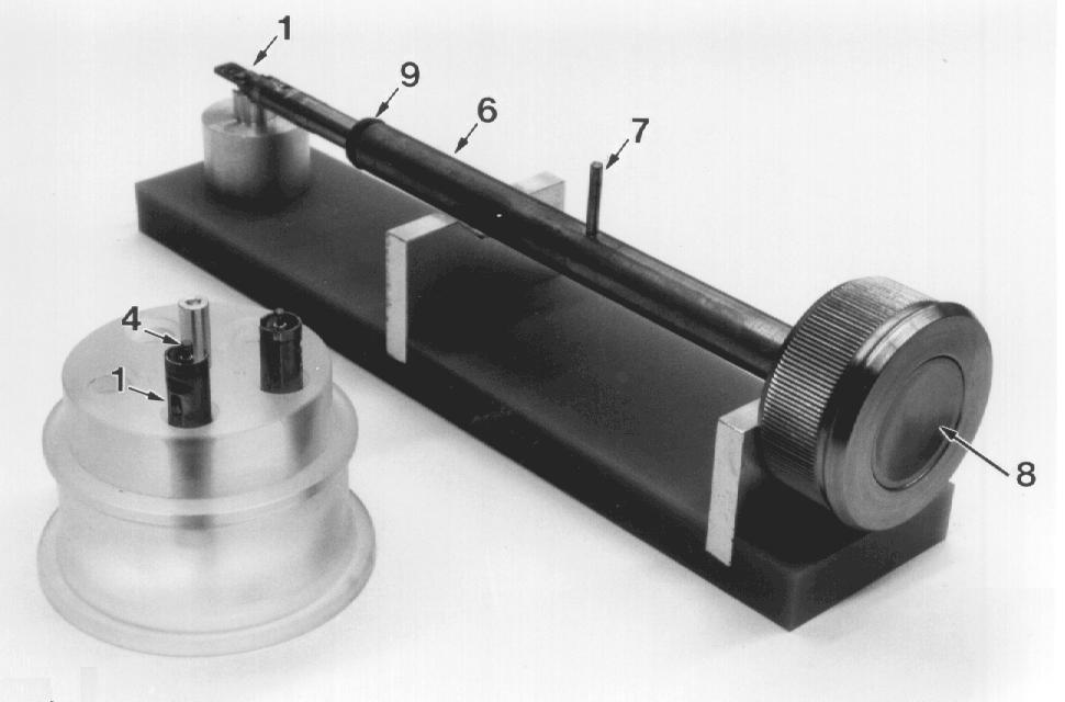
1 Morgagni Operating Instructions ow to operate the microscope/obtain an image 2.1 Starting the microscope Starting the microscope with several manually-operated steps 1. Turn on the water. 2. Switch on the main power switch. 3. Press the "POWER ON" button (on the right hand side control panel). 4. After the program starts press the "VACUUM ON" button. This function can be set to an automatic mode in the Configuration control window of the Morgagni User Interface (UI). 5. If the cooling device or Cold trap is needed, check the liquid nitrogen level in the dewar vessel. It is important that the Vacuum is ready before the cooling device is used! Microscope ready for filament saturation to obtain emission current 1. Press the igh Tension (T) button on the right hand side control panel. 2. Select a igh Tension in the igh Tension control window of the UI and an Emission bias (Step) in the Filament control window. 3. If Autoheating is selected, the filament is automatically heated till the saturation point (if available). To determine the saturation point, Autosaturation can be used (see chapter 1.3.4). 4. Alternatively, manual saturation can be performed by turning the filament knob clockwise or by using the arrow heads of the filament scroll bar in the UI (in the meantime observe the filament pattern on the projection screen till it has completely disappeared from the beam). When this procedure is completed, the saturation point may be fixed by pressing the Filament Limit button in the UI. 2.2 Mounting a specimen in the holder Make sure the specimen holder is clean and remains clean throughout the entire microscopy procedure. A clean specimen holder contributes to the vacuum of the microscope and thus indirect its lifetime! To maintain a clean status of the holder, never touch the front part of the holder (i.e. that part which is located behind the O-ring). For detailed information about maintenance and cleaning see chapter 3, section 3.7. The specimen holder is designed for accepting 3.05 mm diameter gridsupported or disc-shaped specimens with edge thickness up to 0.34 mm. The holder is equipped with a clamping device to fix the specimen (or grid) in its correct position, and a holder carrier to insert the holder into the microscope. Morgagni Operating Instructions
2 Morgagni Operating Instructions Check that the clamping device is clean and dry. Rest the holder on its support (11) with the spring clamp (2) horizontal and uppermost. Fit the tool (supplied by the manufacturer) into the hole at one side of the clamp (2), then lift the clamp to its fullest extent. Carefully place the specimen in the specimen site (3). Check with a magnifying glass to make sure that it is correctly seated. Carefully lower the clamp onto the specimen (or grid) making sure that the specimen remains correctly in position. 2.3 Exchanging Specimen holders Five individual holders and a holder support are supplied with the microscope. These holders can be loaded with different samples in advance and specimens may be exchanged simply by exchanging corresponding holders onto the specimen holder carrier. The specimen holder is released by depressing the push-button (8) on the carrier, and placed into one of the holes in the specimen holder support ( 2-3, 2-4). Another specimen holder can be collected by firstly depressing the pushbutton (8) of the carrier and fitting the injector end (5) of the carrier onto the pin (4) of the specimen holder. Ensure that these two parts are engaged properly, then release the push-button (8) and carry the complete holder to the next step (inserting a specimen holder into the microscope)( 2-3, 2-4) Description of the parts indicated in 2-1 to Specimen older 2. The hole for inserting the tool 3. Clamping device 4. The pin of the specimen holder 5. Injector of the Specimen holder carrier 6. Specimen holder carrier 7. The pin of the specimen holder carrier 8. The push-button of the specimen holder carrier 9. O-ring 10. Carrier support 11. Specimen holder support 12. Airlock 13. The opening of the airlock 14. LED light of the airlock Morgagni Operating Instructions

 010912 2-3")
3 Morgagni Operating Instructions Fig. 2-1 Specimen holder (closed) Fig. 2-2 Specimen holder (open) Morgagni Operating Instructions


4 Morgagni Operating Instructions Fig. 2-3 Specimen holders and injector of the specimen holder carrier Fig. 2-4 Specimen holder including specimen holder carrier Morgagni Operating Instructions

5 Morgagni Operating Instructions Fig. 2-5 Specimen holder support table + holder Fig. 2-6 Specimen holder support table + holder Morgagni Operating Instructions

6 Morgagni Operating Instructions 2.4 Inserting a specimen holder into the microscope The holder is carried by a specimen holder carrier and inserted through a prepumped airlock which ensures that air introduced by the holder is pumped away before the air lock is opened to the microscope column. It is thus not necessary to switch off the filament or high tension when exchanging specimens. Care must, however, be taken that the intensity on the new specimen is not so high as to damage it. old the holder carrier so that the pin (9) points upwards and rotate the carrier approximately 20 degrees clockwise. Insert the carrier into the airlock so that pin 9 engages in the opening (12) of the airlock; the rotary pump is now started (indicator LED lights) (Figure 2-7). Wait (7 to 10 seconds) until LED light is extinguished. Turn the carrier counter-clockwise (approx. 20 degrees) until a stop is encountered and push the carrier in slightly (a few mm) until it stops. Turn the carrier fully counter-clockwise until a firm stop is encountered (half a turn). Push the carrier gently into the microscope until it stops (Figure 2-8). Fully depress the push-button (8) at the end of the carrier. Keep this push-button depressed and pull the carrier out as far as it will go. Release the push-button (8). Turn the carrier clockwise until a firm stop is encountered (half a turn). Condenser apertures Objective apertures Fig. 2-7 Microscope column with apertures and goniometer Morgagni Operating Instructions

7 Morgagni Operating Instructions I Fig. 2-8 Insertion of the specimen holder 2.5 Obtaining an image Use LM to find the specimen on the grid. Select an area of interest and turn to a higher magnification. Select a condenser aperture and re-check its centering. Select an objective aperture and re-check its centering. Focus the image. 2.6 Focusing the image There are two essential steps for completing the focusing procedure: Step 1 Adjust the combination of the small projection screen and binocular. Introduce the small screen fully into the beam. Adjust the inter-ocular distance for maximum comfort. Insert the beam stop and focus the binocular using the ocular adjustment controls. When the shadow of the beam stop is sharp for each eye separately, the binocular is focused and the beam stop can be removed. Morgagni Operating Instructions

8 Morgagni Operating Instructions Fig. 2-9 The beam stop Step 2 Use the amplitude of the wobbler effect to focus the image Insert a specimen and focus the image Press Diffraction push-button. Select a camera length of 350 mm. Focus the illumination using the INTENSITY knob. Ensure that the objective aperture is correctly centered. Press the WOBBLER push-button the right hand side control panel or in the Wobbler control window of the UI): two spots should appear within the area of the objective aperture. If not, using MULTI X and Y to lower the WOBBLER amplitude until they do. The WOBBLER amplitude and azimuth values are displayed (in Multifunction X and Y coordinates) on the Computer monitor. Press DIFFRACTION push-button again to exit diffraction mode, overfocus the spot using INTENSITY knob and focus the image to minimum blur. When finished, press the WOBBLER button once again to switch if off. 2.7 Correction of the astigmatism Astigmatism is an aberration which is present in all electromagnetic lenses. It is caused by asymmetry of the lens field which can result from inherent asymmetries, or from asymmetrical charges on regions close to the beam. There are three possible astigmatism corrections: Spot or Condensor astigmatism for the illumination system, Image or Objective astigmatism for the objective lens and when in Diffraction mode Diffraction astigmatism Astigmatism Correction for the Illumination System The Condenser or Spot stigmator is used to correct astigmatism of the beam. It can be set up for each SPOTSIZE separately and stays the same for all imaging modes Morgagni Operating Instructions
 or the Condensor button in the Stigmator control window of the UI.")
9 Morgagni Operating Instructions Step-by-step procedure (see also chapter 1.3.7): Remove the specimen and the objective aperture from the beam. Push the Spot button on the left hand side control panel (yellow LED on) or the Condensor button in the Stigmator control window of the UI. Astigmatism is corrected when the focused beam remains as circular as possible when going through beam focus (INTENSITY knob). Adjust this using the MULTI X and Y knobs or by using the mouse controlled blue box in the UI (see chapter ). Alternatively, the filament can be undersaturated until structure is visible in the focused beam. Astigmatism is corrected when this structure is as sharp as possible (adjust INTENSITY, MULTI X, Y) Astigmatism of the Objective Lens (Image) The objective lens stigmator corrects image astigmatism. The objective astigmatism can be corrected at four different sensitivities (Figure 2-10). Value 1 and 2 are for igh Magnifications, value 3 is for Diffraction mode and value 4 for Low Magnification and Shadow Projection. Fig Stigmators Step-by-step procedure (Figure 2-11): Obtain a TEM Bright-Field image of the test specimen at high magnification (around 100kx). Press Image stigmator push button (LED on) or activate the Objective button in the Stigmator control window of the UI. Select a very small hole on the specimen (if available). Adjust the FOCUS until the entire hole is slightly overfocused, yet close enough to focus for the fringe asymmetry to be visible (black fringe inside Morgagni Operating Instructions
10 Morgagni Operating Instructions the hole, Figure 2-11A). Change of focus (lower excitation of the objective lens) gives rise to the images in Figure 2-11B and Figure 2-11C. Turn the MULTI X, Y knobs or the mouse controlled blue box in the UI so that the Fresnel fringe is symmetrical when the objective lens is very slightly overfocused. To carry out this procedure, rotate the MULTI X, Y knobs until the setting for minimum astigmatism is obtained (best symmetry for overfocused image). Repeat the same procedure at higher magnifications until the astigmatism is adequately corrected (Figure 2-11D). The criterion for this is that the fringes of uniform width can be seen at one or two steps position overfocus of the finest step size and change of focus (lower excitation of the objective lens produce images as in 2-11E and 2-11F) Image Astigmatism Correction in the LM mode Insert a specimen and centre a structure of interest. Set MAGNIFICATION to the highest LM value (180X). Press IMAGE push-button (LED on). Press the WOBBLER push button. Focus the image so that the blurred structures are as nearly coincident as possible. Adjust the MULTI X, Y knobs until the structures completely overlap. Repeat the last two steps Diffraction pattern Astigmatism Correction Obtain a TEM Bright Field image of a specimen in the M range. Remove specimen and objective aperture from the beam. Set SPOTSIZE knob to position 4. Press DIFFRACTION button on the right hand side control panel. Adjust the MAGNIFICATION knob to obtain the required camera length. Turn INTENSITY knob clockwise until a low intensity of illumination is obtained on the screen. Adjust the FOCUS knob until the diffraction crossover image is obtained. Press the Diffraction button in the UI. Adjust the MULTI X, Y knobs until a symmetrical 3-pointed image (comparable with the Daimler Benz trade sign) is obtained. Alternatively, the mouse controlled blue box in the stigmator control window can be used Morgagni Operating Instructions
11 Morgagni Operating Instructions A D B E C F Fig Image astigmatism correction (small screen + binocular) Morgagni Operating Instructions
12 Morgagni Operating Instructions 2.8 Photography The recording of plate or 35 mm film negatives is operated and controlled by the Camera control window of the UI (see chapter and ) Step-by step procedure a. Select the exposure mode in the UI (Single, Double, Series, Exp. Select). b. If Exp. Select is chosen, make sure that positions are selected in the Stage control window of the UI (see chapter ). c. If Series are selected, select also: The number of exposures in the series. Focus step by STEPSIZE knob. d. Select the exposure time (Auto or Manual); If the Manual mode is selected, ensure that the correct time has been defined; If Auto mode is selected, the measurement can be made either on the main or on the small projection screen. e. Select the film size (6 x 9 cm; 3.25 x 4 inch) of the camera that is used (plate). f. Check the following data: File data Exp. No. Emulsion value Data Int Stock User code Date g. Insert 35 mm camera, if necessary (this can not be done if the CCD camera is mounted at the wide angle (35 mm) port). h. Press the EXPOSURE push button in the UI or the left hand side control panel. The main screen will be automatically raised and lowered. i. During the plate transport plate and exposure phases the illumination of the panel and spotlight as well as the monitor screen intensity are dimmed. j. When the micrograph has been taken, the illumination is restored. k. When the first exposure in DOUBLE mode is made, the screen will display a message: "First exposure finished". After this the main screen will be lowered, the computer will restore the microscope to the viewing condition and a second exposure on the same photo can be made starting from step f. l. Lower the screen (the main screen is lowered automatically after the last exposure has been taken; the small screen has to be lowered manually) or withdraw the 35 mm camera to restore the microscope to the normal viewing condition, if no more exposures are required Morgagni Operating Instructions
 or at the post column position and is continuously exchangeable (see chapter 3.7).")
13 Morgagni Operating Instructions Procedures for Double and Series Exposures, Dark Field Images and Diffraction Patterns are described in chapter 3, section Acquisition of Digital Images For acquisition of digital images the Megaview II CCD camera is used. This camera can be mounted both at the wide angle port (35 mm port) or at the post column position and is continuously exchangeable (see chapter 3.7). Image acquisition and analysis is controlled through the AnalySIS software. The software is displayed at the inner part of the Morgagni User Interface and can be started up by activating the AnalySIS icon in the microscope Start up window (Figure 2-12). Fig Start-Up page The following paragraph displays an introduction into the use of the CCD camera. For more detailed information about the image analysis software, please see the attached user s guide manual of AnalySIS. Morgagni Operating Instructions

14 Morgagni Operating Instructions Image Acquisition Once the Analysis icon has been activated the AnalySIS User Interface appears (Figure 2-13). Fig Analysis For image acquisition the CCD must be first inserted into the proper position. This can be done by pushing the green lit button of the external control box (green button-insertion / red button-retraction) or by pressing the I button in the Analysis UI (Figure 2-14). If the CCD is mounted at the post-column position, the main screen must be lifted as well before image acquisition Fig In / Out After insertion, a live image or a single snapshot can be made. Clicking on the camera button (Figure 2-15A) results in a live image that can be subsequently frozen by clicking on the snapshot button (Figure 2-15B). The acquisition speed of the live mode depends on the exposure time of the camera and can be set in the camera control window which appears after pressing the corresponding button (Figure 2-15C). Fig Live (A), Snapshot (B), Camera Control (C) With the + and the - buttons in the camera control window (Figure 2-16), the speed of image acquisition can be enhanced (-) or decreased (+). It is important to note that the intensity must be adapted to the changes in acquisition. A shorter exposure time requires a higher intensity and vice versa Morgagni Operating Instructions

.")
15 Morgagni Operating Instructions Fig Camera Control For various applications it may be useful to have different modes of acquisition. For screening of samples, focusing and astigmatism correction a high acquisition speed at a somewhat lower image resolution may be sufficient, whereas for a final snapshot image resolution is more important than speed of acquisition. It is possible to define three image acquisition modes with different parameters (Figure 2-17). Fig Three acquisition modes For configuration of the acquisition modes, the Configure Input window must be activated. To do so, select in the taskbar: Image, Configure Input (Figure 2-18). ere, settings can be chosen which are related to the image format (image resolution and binning), automatic gain display, appearance of an on-line intensity histogram or FFT, the exposure time, gain and dark reference, remote control (essential for the correct magnification read-out and stitching) etc. Fig Configure Input After image acquisition it is possible to perform various analyses on the image. Quantification, changing of contrast, brightness, changing of geometry, applying imaging filters, addition of text and symbols etc. For all these jobs, see the AnalySIS instruction manual. Morgagni Operating Instructions
 has the advantage of an increased field of view at a simultaneously enhanced pixel resolution.")
16 Morgagni Operating Instructions Multiple Image Alignment Multiple single images can be digitally stitched to one image. This so called Multiple Image Alignment (MIA) has the advantage of an increased field of view at a simultaneously enhanced pixel resolution. For example: two 1k x 1k digital images can be stitched horizontally and vertically into an almost 2k x 2k image. To perform stitching, a calibration must be carried out for each magnification that is used. To do so, press the Calibrate icon (Figure 2-19: second button on the left). Fig Stitching module When the Calibration button is pressed, the specimen is slightly shifted in both the x and y orientation. A specified image feature (not visible during the procedure) must be recognized throughout the shift. After the calibration, the choice can be made whether to choose a stitching of 2x2 (icon 2), 3x3 (icon 3), 4x4 (icon 4) or 5x5 (icon 5) images (Figure 2-19). The captured images are automatically aligned to the stitched high resolution image. Fig Arrange Multiple Images As an alternative to the prefered automated alignment of the acquired images, it is possible to arrange the multiple images in a manual way. To do so, press the Arrange icon (Figure 2-19: most left button) and the following control window is displayed (Figure 2-20). The way in which the images can be stitched Morgagni Operating Instructions
17 Morgagni Operating Instructions (horizontally, vertically, meander, comb) as well as the number of images for stitching can be defined. The quality value should be preferably at 1. Press the OK button to execute the stitching. In the next control window it is possible to move the position of the indivual images (marked by a red frame) with the left mouse button in order to find the optimal overlap (if required) Removing the specimen holder from the microscope If the injector rod has been removed from the microscope after inserting the specimen, repeat the first five steps as described in chapter 2, section 2.3. Fully depress the push-button (8) on the carrier (Figure 2-8). Keeping the push-button depressed, push the carrier gently into the microscope until it stops. Release the push-button (8). Pull the carrier out as far as possible. Turn the carrier clockwise until a firm stop is encountered (half a turn). Withdraw the carrier from the airlock so that pin 9 comes out of slot 12 (Figure 2-7). The specimen may now be removed from the holder and a new specimen can be inserted Removing a specimen from the holder Rest the specimen holder on its support. Lift the clamping device. Remove the specimen by inverting the holder over a petri dish. Use a tweezer to put the grid into a gridbox. Store the holder with the specimen-securing clamp closed. Morgagni Operating Instructions
Instructions for Tecnai a brief start up manual
 Instructions for Tecnai a brief start up manual Version 3.0, 8.12.2015 Manual of Tecnai 12 transmission electron microscope located at Aalto University's Nanomicroscopy Center. More information of Nanomicroscopy
Operating the Hitachi 7100 Transmission Electron Microscope Electron Microscopy Core, University of Utah
 Operating the Hitachi 7100 Transmission Electron Microscope Electron Microscopy Core, University of Utah Follow the procedures below when you use the Hitachi 7100 TEM. Starting Session 1. Turn on the cold
1. Specimen Holder Removal, Loading, and Insertion
 OPERATION OF THE PHILIPS CM-200 FEG-TEM When not in use, the CM-200 should be in the MICROSCOPE ON configuration with the HIGH TENSION ON (illuminates green when the high tension is on).. The microscope
Please follow these instructions for use of the Philips CM100 TEM. Adopted from website below.
 Please follow these instructions for use of the Philips CM100 TEM. Adopted from website below. http://staff.washington.edu/wpchan/if/cm100_inst.shtml Instructions for the Philips CM100 TEM and peripherals
FEI Tecnai G 2 F20 Operating Procedures
 FEI Tecnai G 2 F20 Operating Procedures 1. Startup (1) Sign-up in the microscope log-sheet. Please ensure you have written an account number for billing. (2) Log in to the computer: Login to your account
1.3. Before loading the holder into the TEM, make sure the X tilt is set to zero and the goniometer locked in place (this will make loading easier).
.") JEOL 200CX operating procedure Nicholas G. Rudawski ngr@ufl.edu (805) 252-4916 1. Specimen loading 1.1. Unlock the TUMI system. 1.2. Load specimen(s) into the holder. If using the double tilt holder, ensure
JEOL 200CX operating procedure Nicholas G. Rudawski ngr@ufl.edu (805) 252-4916 1. Specimen loading 1.1. Unlock the TUMI system. 1.2. Load specimen(s) into the holder. If using the double tilt holder, ensure
MSE 460 TEM Lab 2: Basic Alignment and Operation of Microscope
 MSE 460 TEM Lab 2: Basic Alignment and Operation of Microscope Last updated on 1/8/2018 Jinsong Wu, jinsong-wu@northwestern.edu Aims: The aim of this lab is to familiarize you with basic TEM alignment
1.2. Make sure the viewing screen is covered (exposure to liquid N 2 may cause it to crack).
.") FEI Tecnai F20 S/TEM: imaging in TEM mode Nicholas G. Rudawski ngr@ufl.edu (805) 252-4916 (352) 392-3077 Last updated: 01/21/18 1. Filling the cold trap (if needed) 1.1. Prior to use, the cold trap needs
FEI Tecnai F20 S/TEM: imaging in TEM mode Nicholas G. Rudawski ngr@ufl.edu (805) 252-4916 (352) 392-3077 Last updated: 01/21/18 1. Filling the cold trap (if needed) 1.1. Prior to use, the cold trap needs
2. Raise HT to 200kVby following the procedure explained in 1.6.
 JEOL 2100 MANUAL Quick check list 1. If needed, fill the reservoir with LN2 2. Raise HT to 200kVby following the procedure explained in 1.6. 3. Insert specimen holder into TEM (Insert holder in airlock,
User Operation of JEOL 1200 EX II
 **Log onto Computer** Open item program Start Up Procedure User Operation of JEOL 1200 EX II 1. If scope is not running, locate an electron microscopy technician (EMT) to find out why not. 2. Turn up brightness
Basic Users Manual for Tecnai-F20 TEM
 Basic Users Manual for Tecnai-F20 TEM NB: This document contains my personal notes on the operating procedure of the Tecnai F20 and may be used as a rough guide for those new to the microscope. It may
Procedures for Performing Cryoelectron Microscopy on the FEI Sphera Microscope
 Procedures for Performing Cryoelectron Microscopy on the FEI Sphera Microscope The procedures given below were written specifically for the FEI Tecnai G 2 Sphera microscope. Modifications will need to
How to use the Jeol 1010 TEM of GI (Liesbeth own GI version)
") How to use the Jeol 1010 TEM of GI (Liesbeth own GI version) 1.Load the specimen Load a grid into the rod holder: USE ONLY THE TOP POSITION (blue arrow), Specimen selection on 1 (The rear one is only a
How to use the Jeol 1010 TEM of GI (Liesbeth own GI version) 1.Load the specimen Load a grid into the rod holder: USE ONLY THE TOP POSITION (blue arrow), Specimen selection on 1 (The rear one is only a
JEOL JEM-1400 Transmission Electron Microscope Operating Instructions
 JEOL JEM-1400 Transmission Electron Microscope Operating Instructions Anti-contamination device Objective aperture Objective aperture translation knobs Specimen holder Pump/air switch Left hand control
MSE 595T Transmission Electron Microscopy. Laboratory III TEM Imaging - I
 MSE 595T Basic Transmission Electron Microscopy TEM Imaging - I Purpose The purpose of this lab is to: 1. Make fine adjustments to the microscope alignment 2. Obtain a diffraction pattern 3. Obtain an
CM20 USER GUIDE. Duncan Alexander, CIME 2010
 CM20 USER GUIDE Duncan Alexander, CIME 2010 CM20 START UP AND CHECK LIST 2 SPECIMEN EXCHANGE 5 - REMOVING SAMPLE HOLDER 6 - INSERTING SAMPLE HOLDER 7 TURNING ON HT 8 STARTING THE FILAMENT 9 GUN TILT ALIGNMENT
Full-screen mode Popup controls. Overview of the microscope user interface, TEM User Interface and TIA on the left and EDS on the right
 Quick Guide to Operating FEI Titan Themis G2 200 (S)TEM: TEM mode Susheng Tan Nanoscale Fabrication and Characterization Facility, University of Pittsburgh Office: M104/B01 Benedum Hall, 412-383-5978,
05/20/14 1. Philips CM200T. Standby Condition
 05/20/14 1 Philips CM200T Standby Condition HT and filament off, HT setting at 200kV. RESET HOLDER, center sample tilt knobs, and remove sample. Mag ~ 5-10kX Objective and SA apertures out, C2 aperture
LEO 912 TEM Short Manual. Prepared/copyrighted by RH Berg Danforth Plant Science Center
 LEO 912 TEM Short Manual Prepared/copyrighted by RH Berg Danforth Plant Science Center Specimen holder [1] Never touch the holder (outside of the O-ring, double-headed arrow) because finger oils will contaminate
Protective Equipment Nitrile gloves for handling sample holder and safety glasses for filling liquid nitrogen dewar.
 Emergency Information: 1. Medical Emergencies: Contact 911 and McGill Security 514.398.3000 2. Leave TEM as is. Do NOT shut down the vacuum system. 3. If possible, turn off High Tension and Close Column
Transmission Electron Microscopy 9. The Instrument. Outline
 Transmission Electron Microscopy 9. The Instrument EMA 6518 Spring 2009 02/25/09 Outline The Illumination System The Objective Lens and Stage Forming Diffraction Patterns and Images Alignment and Stigmation
1.1. In regular TEM imaging mode, find a region of interest and set it at eucentric height.
 JEOL 2010F operating procedure Covers operation in STEM mode (See separate procedures for operation in TEM mode and operation of EDS system) Nicholas G. Rudawski ngr@ufl.edu (805) 252-4916 NOTE: this operating
Tecnai T12 Operating Procedures
 Tecnai T12 Operating Procedures I. Initial Procedures 1 II. Accelerating Voltage 3 III. Specimen Loading and Holder Insertion/Removal 3 IV. Emission Current 7 V. Alignment 7 VI. Camera Control and Imaging
Operating Checklist for using the Scanning Electron Microscope, JEOL JSM 6400.
 Smith College August 2005 Operating Checklist for using the Scanning Electron Microscope, JEOL JSM 6400. CONTENT, page no. Pre-Check, 1 Specimen Insertion, 1 Startup, 2 Filament Saturation, 2 Beam Alignment,
SAMUEL ROBERTS NOBLE ELECTRON MICROSCOPY LABORATORY. Operating Procedures for the Zeiss 9 S-2. Transmission Electron Microscope
 1 SAMUEL ROBERTS NOBLE ELECTRON MICROSCOPY LABORATORY Operating Procedures for the Zeiss 9 S-2 Transmission Electron Microscope Prepared by Dr. Scott D. Russell Department of Botany and Microbiology September,
OPERATION OF THE HITACHI S-450 SCANNING ELECTRON MICROSCOPE. by Doug Bray Department of Biological Sciences University of Lethbridge
 OPERATION OF THE HITACHI S-450 SCANNING ELECTRON MICROSCOPE by Doug Bray Department of Biological Sciences University of Lethbridge Revised September, 2000 Note: The terms in bold in this document represent
STANDARD OPERATING PROCEDURE: JEOL TEM-2100
 STANDARD OPERATING PROCEDURE: JEOL TEM-2100 Purpose of this Instrument: Essential tool for structural characterization of natural or synthesized nanostructures. Location: WVU - Engineering Sciences Building
JEOL 6500 User Manual
 LOG IN to your session on the computer to the left of the microscope. Starting Conditions 1. Press Ctrl-Alt-Del and log on to the microscope computer. Click on JEOL PC SEM 6500 icon. Click yes if message
This document assumes the user is already familiar with basic operation of the instrument in TEM mode and use of the digital camera.
 FEI Tecnai F20 S/TEM: acquiring diffraction patterns Nicholas G. Rudawski ngr@ufl.edu (805) 252-4916 (352) 392-3077 Last updated: 10/18/17 This document assumes the user is already familiar with basic
This document assumes the user is already familiar with basic operation of the instrument in TEM mode and use of the Microscope Control interface.
 FEI Tecnai F20 S/TEM: imaging in STEM mode Nicholas G. Rudawski ngr@ufl.edu (805) 252-4916 (352) 392-3077 Last updated: 05/10/18 This document assumes the user is already familiar with basic operation
Operating Checklist for using the Scanning Electron. Microscope, JEOL JSM 6400.
 Smith College August 2009 Operating Checklist for using the Scanning Electron Microscope, JEOL JSM 6400. CONTENT, page no. Pre-Check 1 Startup 1 Specimen Insertion 2 Filament Saturation 2 Beam Alignment
MSE 460 TEM Lab 4: Bright/Dark Field Imaging Operation
 MSE 460 TEM Lab 4: Bright/Dark Field Imaging Operation Last updated on 1/8/2018 Jinsong Wu, jinsong-wu@northwestern.edu Aims: The aim of this lab is to familiarize you with bright/dark field imaging operation.
Jeol JEM Responsible personell: Endy ( ) Online booking is compulsory!
 Online booking is compulsory!") Jeol JEM 1230 Responsible personell: Endy (45279377) Online booking is compulsory! After training you will have access to working alone on the instrument. All insertion of samples is done by responsible
Jeol JEM 1230 Responsible personell: Endy (45279377) Online booking is compulsory! After training you will have access to working alone on the instrument. All insertion of samples is done by responsible
COMPACT MANUAL FOR GI USERS OF THE JEM 1400 FLASH BEGINNERS (For internal use only) Gray means additional information at the end of this mini-manual
 Gray means additional information at the end of this mini-manual") 1 COMPACT MANUAL FOR GI USERS OF THE JEM 1400 FLASH BEGINNERS (For internal use only) Gray means additional information at the end of this mini-manual ABOUT THIS MICROSCOPE (room HG01.240) The JEM-1400Flash
1 COMPACT MANUAL FOR GI USERS OF THE JEM 1400 FLASH BEGINNERS (For internal use only) Gray means additional information at the end of this mini-manual ABOUT THIS MICROSCOPE (room HG01.240) The JEM-1400Flash
User Manual. Digital Compound Binocular LED Microscope. MicroscopeNet.com
 User Manual Digital Compound Binocular LED Microscope Model MD82ES10 MicroscopeNet.com Table of Contents i. Caution... 1 ii. Care and Maintenance... 2 1. Components Illustration... 3 2. Installation...
Standard Operating Procedure for the Amray 1810 Scanning Electron Microscope Version: 29 NOVEMBER 2014
 Standard Operating Procedure for the Amray 1810 Scanning Electron Microscope Version: 29 NOVEMBER 2014 1. Utility Requirements a. System power is supplied by two 120 VAC/20 A circuits. When doing maintenance
INSTRUCTIONS JEM-2010F FIELD-EMISSION TRANSMISSION ELECTRON MICROSCOPE WITH STEM CAPABILITY
 INSTRUCTIONS JEM-2010F FIELD-EMISSION TRANSMISSION ELECTRON MICROSCOPE WITH STEM CAPABILITY August 2011 PRELIMINARIES OPERATION 1. Ensure that EMISSION and HT are on: The HT READY and FEG READY lights
1. Preliminary sample preparation
 FEI Helios NanoLab 600 standard operating procedure Nicholas G. Rudawski ngr@ufl.edu (352) 392 3077 (office) (805) 252-4916 (cell) Last updated: 03/02/18 What this document provides: an overview of basic
JEOL JEM 2010 TRAINING TRANSMISSION ELECTRON MICROSCOPE USER MANUAL
 JEOL JEM 2010 TRAINING TRANSMISSION ELECTRON MICROSCOPE USER MANUAL Version 5.1 EM Facility CMSE-SEF Massachusetts Institution of Technology TABLE OF CONTENTS 1. Specifications...2 1.1 Performance...2
ML7520 ML7530 DIOPTER ADJUSTMENT RING BINOCULAR BODY, INCLINED 30. (a) Field Iris Control Lever. (c) Filter Slots EYEPIECES, KHW10X
 Field Iris Control Lever. (c) Filter Slots EYEPIECES, KHW10X") JAPAN DIOPTER ADJUSTMENT RING BINOCULAR BODY, INCLINED 30 (a) Field Iris Control Lever (c) Filter Slots EYEPIECES, KHW10X ANALYZER CONTROL LEVER (b) Aperture Iris Control Lever LIGHT SOURCE HOUSING VERTICAL
JAPAN DIOPTER ADJUSTMENT RING BINOCULAR BODY, INCLINED 30 (a) Field Iris Control Lever (c) Filter Slots EYEPIECES, KHW10X ANALYZER CONTROL LEVER (b) Aperture Iris Control Lever LIGHT SOURCE HOUSING VERTICAL
STEM alignment procedures
 STEM alignment procedures Step 1. ASID alignment mode 1. Write down STD for TEM, and then open the ASID control window from dialogue. Also, start Simple imager viewer program on the Desktop. 2. Click on
Introduction: Why electrons?
 Introduction: Why electrons? 1 Radiations Visible light X-rays Electrons Neutrons Advantages Not very damaging Easily focused Eye wonderful detector Small wavelength (Angstroms) Good penetration Small
Tecnai on-line help manual --
 Tecnai on-line help Alignments 1 Tecnai on-line help manual -- Alignments Table of Contents 1 Alignments in the Tecnai microscope...5 2 Alignment procedures...6 3 Introduction to electron optics...11 3.1
FEI Falcon Direct Electron Detector. Best Practice Document
 FEI Falcon Direct Electron Detector Best Practice Document 2 1. Introduction FEI Falcon Direct Electron Detector Best Practice Application Guide The FEI Falcon Detector is based on direct electron detection
Last updated 6/12/18. F20 User Manual at the Simons Electron Microscopy Center
 F20 User Manual at the Simons Electron Microscopy Center 1 Table of Contents F20 Information Sheet 2 F20 User Guide (starting your session) 3 F20 User Guide (ending your session) 5 Cryo Screening with
OMM300. Inverted Metallurgical Microscope
 OMM300 Inverted Metallurgical Microscope Instruction Manual Please read the instructions carefully before operating CONTENTS Safety 2 Parts List 2 Features 3 Assembly 5 Operation 7 Maintenance 9 Specifications
FEI Titan Image Corrected STEM
 05/03/16 1 FEI Titan 60-300 Image Corrected STEM Standby Condition HT setting at 300kV, Col. Valves Closed RESET Holder and remove sample. Mag ~ 5-10kX Objective and SA apertures out, C2 aperture at 150µm
User Manual. Trinocular Metallurgical Microscope. MicroscopeNet.com
 User Manual Trinocular Metallurgical Microscope Model M83MPTR MicroscopeNet.com Table of Contents i. Caution.. 1 ii. Care and Maintenance... 2 1. Components Illustration..... 3 2. Installation...4 3. Operation
NANO 703-Notes. Chapter 9-The Instrument
 1 Chapter 9-The Instrument Illumination (condenser) system Before (above) the sample, the purpose of electron lenses is to form the beam/probe that will illuminate the sample. Our electron source is macroscopic
Title: Amray 1830 SEM#2 Semiconductor & Microsystems Fabrication Laboratory Revision: D Rev Date: 03/18/2016
 Approved by: Process Engineer / / / / Equipment Engineer 1 SCOPE The purpose of this document is to detail the use of the Amray 1830 SEM. All users are expected to have read and understood this document.
Be aware that there is no universal notation for the various quantities.
 Fourier Optics v2.4 Ray tracing is limited in its ability to describe optics because it ignores the wave properties of light. Diffraction is needed to explain image spatial resolution and contrast and
Motorized Axio Observer Start-up instructions
 Start-up instructions 1. If using fluorescence turn on Fluorescent light source. TL light Source (Hal 100) 2. Turn on microscope using switch on lower left side of the microscope. 3. If imaging, turn on
CAPTURING IMAGES ON THE HIGH-MAGNIFICATION MICROSCOPE
 University of Virginia ITC Academic Computing Health Sciences CAPTURING IMAGES ON THE HIGH-MAGNIFICATION MICROSCOPE Introduction The Olympus BH-2 microscope in ACHS s microscope lab has objectives from
JEOL 6700 User Manual 05/18/2009
 JEOL 6700 User Manual 05/18/2009 LOG IN to your session on the computer to the right of the microscope. Starting Conditions 1. Click the button and read the Penning Gauge to ensure that the microscope
SWIFT SERIES M2252DGL MICROSCOPE
 SWIFT SERIES M2252DGL MICROSCOPE The M2252DGL Series is ideal for elementary to high school classrooms. Built to withstand student use, this series has locked-on eyepieces, objectives, illuminator housing
Using the Nikon TE2000 Inverted Microscope
 Wellcome Trust Centre for Human Genetics Molecular Cytogenetics and Microscopy Core Using the Nikon TE2000 Inverted Microscope Fluorescence image acquisition using Scanalytic s IPLab software and the B&W
BX-61: Brightfield Instruction /Continue to scroll for Fluorescent Instuctions
 BX-61: Brightfield Instruction /Continue to scroll for Fluorescent Instuctions Starting up: Schematic of Olympus BX-61. 1. Turn on Olympus microscope power box (left of microscope) with toggle switch on
Eyepieces KHW10X. Diopter Adjustment Ring. Binocular Body Inclined 30. Binocular Clamp Screw. Analyzer control Lever. Reflected Light Illuminator
 JAPAN Eyepieces KHW10X Diopter Adjustment Ring Binocular Body Inclined 30 Binocular Clamp Screw Analyzer control Lever Reflected Light Illuminator Ball-Bearing Objective Nosepiece Objectives Large Scan
Dickinson College Department of Geology
 Dickinson College Department of Geology Title: Equipment: BASIC OPERATION OF THE SCANNING ELECTRON MICROSCOPE (SEM) JEOL JSM-5900 SCANNING ELECTRON MICROSCOPE Revision: 2.2 Effective Date: 1/29/2003 Author(s):
UNIVERSITY OF WATERLOO Physics 360/460 Experiment #2 ATOMIC FORCE MICROSCOPY
 UNIVERSITY OF WATERLOO Physics 360/460 Experiment #2 ATOMIC FORCE MICROSCOPY References: http://virlab.virginia.edu/vl/home.htm (University of Virginia virtual lab. Click on the AFM link) An atomic force
SEM OPERATION IN LOW VACUUM MODE
 SEM OPERATION IN LOW VACUUM MODE Instructions for JEOL 5800 LV The EVAC light of the SEM specimen chamber should be already lit when you approach the SEM & the SEM will have been left in the high vacuum
Talos on-line help User interface 1 Software version 1.6 and higher
 Talos on-line help User interface 1 Talos on-line help manual -- User interface Table of Contents 1 User Interface... 3 1.1 View modes... 4 1.2 Workset tabs... 4 1.3 Control panels... 5 1.4 Popup panels...
Zoom Stereo Microscope NYMCS-360 Instruction Manual
 Zoom Stereo Microscope NYMCS-60 Instruction Manual This manual is written for stereo microscope NYMCS-60. To ensure the safety, obtain optimum performance and to familiarize yourself fully with the use
Scanning Electron Microscope FEI INSPECT F50. Step by step operation manual
 Scanning Electron Microscope FEI INSPECT F50 Step by step operation manual Scanning Electron Microscope, FEI Inspect F50 FE-SEM-F Observation Flow Saving Data And Analysis Specimen preparation Error check
JEOL 2010 FasTEM & DigitalMicrograph User's Guide
 JEOL 2010 FasTEM & DigitalMicrograph User's Guide Electron Microscopy Laboratory Instititute of Materials Science University of Connecticut The purpose of this manual is to remind you of the essential
FRAUNHOFER AND FRESNEL DIFFRACTION IN ONE DIMENSION
 FRAUNHOFER AND FRESNEL DIFFRACTION IN ONE DIMENSION Revised November 15, 2017 INTRODUCTION The simplest and most commonly described examples of diffraction and interference from two-dimensional apertures
SEM Training Notebook
 SEM Training Notebook Lab Manager: Dr. Perry Cheung MSE Fee-For-Service Facility Materials Science and Engineering University of California, Riverside December 21, 2017 (rev. 3.4) 1 Before you begin Complete
Operating F20/F30 with SerialEM
 Chen Xu xuchen@brandeis.ede $BrandeisEM: ~emdoc-xml/en_us.iso8859-1/articles/operating-f20-or-f30/article.xml, 1 2013-01-19 01:42:20 xuchen Exp$ This is a quick check list for the Tecnai F20 or Tecnai
JSM 6060 LV SCANNING ELECTRON MICROSCOPE STANDARD OPERATING PROCEDURES
 JSM 6060 LV SCANNING ELECTRON MICROSCOPE STANDARD OPERATING PROCEDURES RULES All users must go through a series of standard operation procedure training. For more information contact: Longlong Liao Teaching
Basic Operating Instructions for Strata Dual Beam 235 FIB/SEM
 Basic Operating Instructions for Strata Dual Beam 235 FIB/SEM Warning Always adjust your specimen height before closing the chamber door to make sure your specimen will not hit the bottom of the lens;
STEM Spectrum Imaging Tutorial
 STEM Spectrum Imaging Tutorial Gatan, Inc. 5933 Coronado Lane, Pleasanton, CA 94588 Tel: (925) 463-0200 Fax: (925) 463-0204 April 2001 Contents 1 Introduction 1.1 What is Spectrum Imaging? 2 Hardware 3
SEM Training Notebook
 SEM Training Notebook Lab Manager: Dr. Perry Cheung MSE Fee-For-Service Facility Materials Science and Engineering University of California, Riverside March 8, 2018 (rev. 3.5) 1 Before you begin Complete
Section 1: TEM parts and functions... 2
 Introduction The set of instructions below are written by Charlie Sanabria within the first few sessions of his TEM training process, and are intended for anyone interested in viewing the TEM operation
Quick Operation Guide
 Quick Operation Guide Power ON Mounting specimens Set the specimen on the sample holder, and install the sample holder to the holder frame. Attach the holder frame to the XY stage. Type of holder Main
Tecnai on-line help User interface 1 Tecnai F20 Tecnai F30 User interface Software version 2.1.8/3.0
 Tecnai on-line help User interface 1 Tecnai on-line help manual -- User interface Table of Contents 1 User Interface...5 1.1 View modes...6 1.2 Toolbar...6 1.3 Workset tabs...7 1.4 Control panels...7 1.5
User Manual. Digital Compound Binocular LED Microscope. MicroscopeNet.com
 User Manual Digital Compound Binocular LED Microscope Model MD827S30L series MicroscopeNet.com Table of Contents i. Caution... 1 ii. Care and Maintenance... 2 1. Components Illustration... 3 2. Installation...
S200 Course LECTURE 1 TEM
 S200 Course LECTURE 1 TEM Development of Electron Microscopy 1897 Discovery of the electron (J.J. Thompson) 1924 Particle and wave theory (L. de Broglie) 1926 Electromagnetic Lens (H. Busch) 1932 Construction
Zeiss Axio Imager.A1 manual
 Zeiss Axio Imager.A1 manual Power-up protocol 1. Mercury lamp 2. Power strip on shelf 3. Computer The Mercury lamp should always be first-on and last-off. This prevents any electrical surges caused by
Digital Microscope. User Manual
 Digital Microscope User Manual Features The digital microscope provides 10~200X adjustable magnification range. The build-in high-performance white LED can illuminate the object without using any auxiliary
STEINDORFF NYMC Polarizing Microscope
 NYMC38000 Polarizing Microscope In order to exert performance of this microscope and to ensure the safety, please read the operating instruction carefully before use. 1 I. APPLICATION: NYMC38000 series
Contents STARTUP MICROSCOPE CONTROLS CAMERA CONTROLS SOFTWARE CONTROLS EXPOSURE AND CONTRAST MONOCHROME IMAGE HANDLING
 Operations Guide Contents STARTUP MICROSCOPE CONTROLS CAMERA CONTROLS SOFTWARE CONTROLS EXPOSURE AND CONTRAST MONOCHROME IMAGE HANDLING Nikon Eclipse 90i Operations Guide STARTUP Startup Powering Up Fluorescence
Zeiss AxioImager.Z2 Brightfield Protocol
 Zeiss AxioImager.Z2 Brightfield Protocol 1) System Startup Please note put sign-up policy. You must inform the facility at least 24 hours beforehand if you can t come; otherwise, you will receive a charge
INTRODUCTION THIN LENSES. Introduction. given by the paraxial refraction equation derived last lecture: Thin lenses (19.1) = 1. Double-lens systems
 = 1. Double-lens systems") Chapter 9 OPTICAL INSTRUMENTS Introduction Thin lenses Double-lens systems Aberrations Camera Human eye Compound microscope Summary INTRODUCTION Knowledge of geometrical optics, diffraction and interference,
Chapter 9 OPTICAL INSTRUMENTS Introduction Thin lenses Double-lens systems Aberrations Camera Human eye Compound microscope Summary INTRODUCTION Knowledge of geometrical optics, diffraction and interference,
INSTRUCTIONS FOR COURSE WORK 4 (AxioVert) Instructor: Anne Vaahtokari (MIU) 1. Purpose of the work
 Instructor: Anne Vaahtokari (MIU) 1. Purpose of the work") INSTRUCTIONS FOR COURSE WORK 4 (AxioVert) Instructor: Anne Vaahtokari (MIU) 1. Purpose of the work In this work, you will get familiar with an inverted epifluorescence microscope. Also, you will learn
INSTRUCTIONS FOR COURSE WORK 4 (AxioVert) Instructor: Anne Vaahtokari (MIU) 1. Purpose of the work In this work, you will get familiar with an inverted epifluorescence microscope. Also, you will learn
--> Buy True-PDF --> Auto-delivered in 0~10 minutes. JY/T
 Translated English of Chinese Standard: JY/T011-1996 www.chinesestandard.net Sales@ChineseStandard.net INDUSTRY STANDARD OF THE JY PEOPLE S REPUBLIC OF CHINA General rules for transmission electron microscopy
Instruction Manual T Binocular Acromat Research Scope T Trinocular Acromat Research Scope
 Research Scope Instruction Manual T-29031 Binocular Acromat Research Scope T-29041 Trinocular Acromat Research Scope T-29032 Binocular Semi-Plan Research Scope T-29042 Trinocular Semi-Plan Research Scope
Very short introduction to light microscopy and digital imaging
 Very short introduction to light microscopy and digital imaging Hernan G. Garcia August 1, 2005 1 Light Microscopy Basics In this section we will briefly describe the basic principles of operation and
Nikon Ti-E Microscope Manual. Rightmire Hall Ohio State University. Director: Tony Brown Rightmire
 Nikon Ti-E Microscope Manual Rightmire Hall Ohio State University Director: Tony Brown Rightmire 060 292-1205 brown.2302@osu.edu Facility Manager: Paula Monsma Rightmire 062 293-0939 292-1367 monsma.1@osu.edu
Manual for BMS E1 eplan series, compound microscope
 Manual for BMS E1 eplan series, compound microscope The compound microscope allows it to study, at cell level, structures of textures of botanical and zoological nature. (e.g. slides of roots, leaves and
Low Voltage Electron Microscope
 LVEM 25 Low Voltage Electron Microscope fast compact powerful Delong America FAST, COMPACT AND POWERFUL The LVEM 25 offers a high-contrast, high-throughput, and compact solution with nanometer resolutions.
Cryo-Electron Microscopy of Viruses
 Blockkurs Biophysic and Structural Biology 2013 Praktikumsversuch at C-CINA Cryo-Electron Microscopy of Viruses In this practical we will compare electron microscopy of negatively stained and frozen-hydrated
Biology 29 Cell Structure and Function Spring, 2009 Springer LABORATORY 1: THE LIGHT MICROSCOPE
 Biology 29 Cell Structure and Function Spring, 2009 Springer LABORATORY 1: THE LIGHT MICROSCOPE Prior to lab: 1) Read these instructions (p 1-6) 2) Go through the online tutorial, the microscopy pre-lab
Introduction of New Products
 Field Emission Electron Microscope JEM-3100F For evaluation of materials in the fields of nanoscience and nanomaterials science, TEM is required to provide resolution and analytical capabilities that can
Things to check before start-up.
 Byeong Cha Page 1 11/24/2009 Manual for Leica SP2 Confocal Microscope Enter you name, the date, the time, and the account number in the user log book. Things to check before start-up. Make sure that your
LVEM 25. Low Voltage Electron Mictoscope. fast compact powerful
 LVEM 25 Low Voltage Electron Mictoscope fast compact powerful FAST, COMPACT AND POWERFUL The LVEM 25 offers a high-contrast, high-throughput, and compact solution with nanometer resolutions. All the benefits
Marine Invertebrate Zoology Microscope Introduction
 Marine Invertebrate Zoology Microscope Introduction Introduction A laboratory tool that has become almost synonymous with biology is the microscope. As an extension of your eyes, the microscope is one
Titan on-line help manual -- User Interface
 1 Titan on-line help manual -- User Interface Table of Contents 1 User Interface... 6 1.1 View modes... 7 1.2 Workset tabs... 7 1.3 Control panels... 7 1.4 Popup panels... 9 1.5 Display... 12 1.5.1 Binding
Chapter 2 Instrumentation for Analytical Electron Microscopy Lecture 7. Chapter 2 CHEM Fall L. Ma
 Chapter 2 Instrumentation for Analytical Electron Microscopy Lecture 7 Outline Electron Sources (Electron Guns) Thermionic: LaB 6 or W Field emission gun: cold or Schottky Lenses Focusing Aberration Probe
Welcome 1. Precaution
 Table of Contents EN Precaution....2 Preparation.. 4 Standard accessories....4 Parts Names & Functions...5 Computer System requirements.... 6 Technical Specifications 7 Install the software.. 7 Start Microscope.8
Easy Kohler Illumination Method
 Easy Kohler Illumination Method ACADEMIC SKILLS CENTRE (ASC) A. Silverberg Completion of a Kohler illumination method is required before a microscope can be used efficiently. The Kohler method is designed