EE 330 Lecture 11. Capacitances in Interconnects Back-end Processing
|
|
|
- Howard Robbins
- 5 years ago
- Views:
Transcription
1 EE 330 Lecture 11 Capacitances in Interconnects Back-end Processing
2 Exam 1 Friday Sept 21 Students may bring 1 page of notes HW assignment for week of Sept 16 due on Wed Sept 19 at beginning of class No 5:00 p.m extension so solutions can be posted Those with special accommodation needs, please send me an message or contact me so arrangements can be made Review session to be determined
3 Review from Last Lecture Dual-Damascene Process Patterning of Copper Copper Deposited on Surface CMP Target
4 Review from Last Lecture Resistance in Interconnects W L R=R [L / W] The Number of Squares approach to resistance determination in thin films N S = 21 L / W=21 R=R N S
5 Review from Last Lecture Resistance in Interconnects (can be used to build resistors!) Serpentine often used when large resistance required Polysilicon or diffusion often used for resistor creation Effective at managing the aspect ratio of large resistors May include hundreds or even thousands of squares
6 Review from Last Lecture Resistance in Interconnects (can be used to build resistors!) d 2 2 d 1 Area requirements determined by both minimum width and minimum spacing design rules
7 Capacitance in Interconnects C=C D A C D is the capacitance density and A is the area of the overlap
8 Capacitance in Interconnects Metal 2 A 3 Metal 1 A 1 A 5 A 2 A 4 Substrate M 2 M 1 SUB C 12 C 2S C 1S Equivalent Circuit C 12 =CD 12 A 5 C 1S =CD 1S (A 1 +A 2 +A 5 ) C 2S =CD 2S (A 3 +A 4 )
9 Example Two metal layers, Metal 1 and Metal 2, are shown. Both are above field oxide. Determine the capacitance between Metal 1 and Metal 2. Assume the process has capacitance densities from M 1 to substrate of.05ff/u 2, from M 1 to M 2 of.07ff/u 2 and from M 2 to substrate of.025ff/u 2. 30µ 10µ Metal 1 Metal 2 30µ 30µ 10µ 30µ
10 Example Solution 30µ 10µ 30µ 30µ 10µ 30µ A C1C μ 400μ 30µ The capacitance density from M 1 to M 2 is.07ff/u C12 AC1C2 CD fF/ 28fF
11 Capacitance and Resistance in Interconnects See MOSIS WEB site for process parameters that characterize parasitic resistances and capacitances
12
13
14
15
16 Example Determine the resistance and capacitance of a Poly interconnect that is 0.6u wide and 800u long and compare that with the same interconnect if M 1 were used. Assume a 0.18u process. 0.6µ POLY 800µ R =n R POLY SQ SH C P-SUB =A C R SH =? R DPS =? DPS
17 For 0.18u process R SH =7.7Ω/ C DPS =103 af/µ 2
18 Example For 0.18u process Determine the resistance and capacitance of a Poly interconnect that is 0.6u wide and 800u long and compare that with the same interconnect if M 1 were used. 0.6µ POLY n SQ µ A= R =n R = =31.3KΩ POLY SQ SH 2-2 C =A C =480μ 84aFμ =40.3fF P-SUB DPS
19 Example Determine the resistance and capacitance of a Poly interconnect that is 0.6u wide and 800u long and compare that with the same interconnect if M 1 were used. 0.6µ Metal 1 800µ
20 For 0.18u process R SH =0.08Ω/ C DPS =39 af/µ 2
21 Example For 0.18u process Determine the resistance and capacitance of a Poly interconnect that is 0.6u wide and 800u long and compare that with the same interconnect if M 1 were used. 0.6µ Metal 1 n SQ µ A= R =n R = =107Ω M1 SQ SH 2 2 C =A C =480μ 39aFμ =18.7fF M1-SUB DM1S
22 IC Fabrication Technology Crystal Preparation Masking Photolithographic Process Deposition Etching Diffusion Ion Implantation Oxidation Epitaxy Polysilicon Contacts, Interconnect and Metalization Planarization

23 Planarization Planarization used to keep surface planar during subsequent processing steps Important for creating good quality layers in subsequent processing steps Mechanically planarized
24 Back End Front End Generic Process Flow Wafer Fabrication Mask Fabrication Epitaxy Grow or Apply Photoresist Deposit or Implant Etch Strip Planarization Wafer Probe Wafer Dicing Die Attach Wire Attach (bonding) Package Test Ship
25 Front End Process Integration for Fabrication of ICs Once for each mask Wafer Fabrication Mask Fabrication Epitaxy Photoresist Deposit or Implant Etch Strip Planarize Back End Processing
26 Front-End Process Flow Front-end processing steps analogous to a recipe for manufacturing an integrated circuit Recipes vary from one process to the next but the same basic steps are used throughout the industry Details of the recipe are generally considered proprietary
27 Back-End Process Flow Wafer Probe Wafer Dicing Die Attach Wire Attach (bonding) Package Test Ship

28 Wafer Dicing
29 Die Attach 1. Eutectic 2. Pre-form 3. Conductive Epoxy
30 Electrical Connections (Bonding) Wire Bonding Bump Bonding
31 Wire Bonding Wire gold or aluminum 25 in diameter
32 Wire Bonding Excellent Annimation showing process at :
33 Wire Bonding Ball Bond Wedge Bond
34 Ball Bonding Steps

35 Ball Bonding Tip Approx 25µ

36 Wire Bonding Ball Bond Termination Bond Ball Bond Photograph

37 Bump Bonding
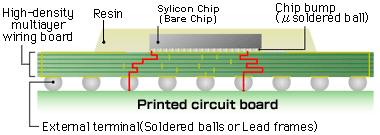
38 Packaging 1. Many variants in packages now available 2. Considerable development ongoing on developing packaging technology 3. Cost can vary from few cents to tens of dollars 4. Must minimize product loss after packaged 5. Choice of package for a product is serious business 6. Designer invariably needs to know packaging plans and package models
39 Packaging

40 Packaging

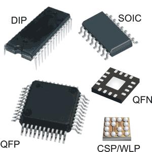
41 Pin Pitch Varies with Package Technology display/234467/articles/advanced-packaging/volume- 14/issue-8/features/the-back-end-process/materials-andmethods-for-ic-package-assemblies.htm From Wikipedia, Sept 20,
42 Many standard packages available today:
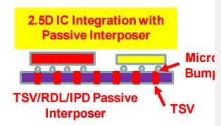
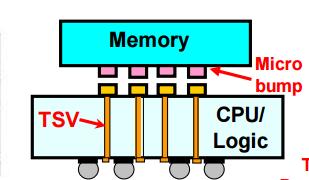
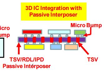
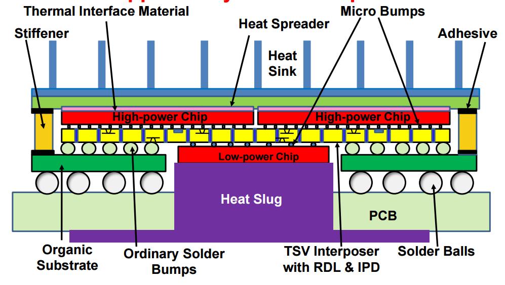
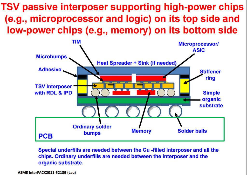
43 Considerable activity today and for years to come on improving packaging technology Multiple die in a package Three-dimensional chip stacking Multiple levels of interconnect in stacks Through silicon via technology Power and heat management Cost driven and cost constrained
44 The following few slides come from a John Lau presentation
45
46
47
48
49 Back-End Process Flow Wafer Probe Wafer Dicing Die Attach Wire Attach (bonding) Package Test Ship
50 Testing of Integrated Circuits Bench testing used to qualify parts for production Most integrated circuits are tested twice during production Wafer Probe Testing Quick test for functionality Usually does not include much parametric testing Relatively fast and low cost test Package costs often quite large Critical to avoid packaging defective parts Packaged Part Testing Testing costs for packaged parts can be high Extensive parametric tests done at package level for many parts Data sheet parametrics with Max and Min values are usually tested on all Ics Data sheet parametrics with Typ values are seldom tested Occasionally require testing at two or more temperatures but this is costly Critical to avoid packaging defective parts


51 Bench Test Environment Photos from www postings and Google image search 62

52 Bench Test Environment Test LAB Photo courtesy of Texas Instruments 63

53 Probe Test Probes on section of probe card Photos from www postings and Google image search 64


54 Probe Test Pad showing probe marks Pad showing bonding wire Die showing wire bonds to package cavity Photos from www postings and Google image search 65


55 Probe Test Production probe test facility Goal to Identify defective die on wafer Photos from www postings and Google image search 66
 Main Frame ATE Automated Test Equipment (ATE)")
56 Work Station Final Test Typical ATE System (less handler) Main Frame ATE Automated Test Equipment (ATE) Test Head
 DIB Cavity (for")


57 Device Interface Board - DIB (Load Board) DIB Cavity (for DUT) DIBs Vary Considerably from one ATE Platform to another and are often personalized for a particular DUT Socket (Contactor)

")
58 Octal Site DIB Flex Octal (Teradyne) Bottom Top

59 Final Test Typical ATE Configuration Handler Tester Test Head Atlas (SSI Robotics)
60 End of Lecture 11
EE 330 Fall 2016 Seating
 EE 330 Fall 2016 Seating 1 2 3 4 5 6 7 8 9 1 Brandon Baxter Zachary Bennett Steven Warren Jakub Hladik Timothy Lindquist Jacob Johnson William Henthorn Daniel Griffen 2 Xiang Li Yi Qiu Benjamin Gisler
EE 330 Lecture 7. Design Rules. IC Fabrication Technology Part 1
 EE 330 Lecture 7 Design Rules IC Fabrication Technology Part 1 Review from Last Time Technology Files Provide Information About Process Process Flow (Fabrication Technology) Model Parameters Design Rules
CMOS Digital Integrated Circuits Lec 2 Fabrication of MOSFETs
 CMOS Digital Integrated Circuits Lec 2 Fabrication of MOSFETs 1 CMOS Digital Integrated Circuits 3 rd Edition Categories of Materials Materials can be categorized into three main groups regarding their
(a) (d) (e) (b) (c) (f) 3D-NAND Flash and Its Manufacturing Process
 (d) (e) (b) (c) (f) 3D-NAND Flash and Its Manufacturing Process") 3D-NAND Flash and Its Manufacturing Process 79 (d) Si Si (b) (c) (e) Si (f) +1-2 (g) (h) Figure 2.33 Top-down view in cap oxide and (b) in nitride_n-2; (c) cross-section near the top of the channel; top-down
3D-NAND Flash and Its Manufacturing Process 79 (d) Si Si (b) (c) (e) Si (f) +1-2 (g) (h) Figure 2.33 Top-down view in cap oxide and (b) in nitride_n-2; (c) cross-section near the top of the channel; top-down
Lecture: Integration of silicon photonics with electronics. Prepared by Jean-Marc FEDELI CEA-LETI
 Lecture: Integration of silicon photonics with electronics Prepared by Jean-Marc FEDELI CEA-LETI Context The goal is to give optical functionalities to electronics integrated circuit (EIC) The objectives
21 rue La Noue Bras de Fer Nantes - France Phone : +33 (0) w7-foldite :
 w7-foldite :") 21 rue La Noue Bras de Fer 44200 - Nantes - France Phone : +33 (0) 240 180 916 - email : info@systemplus.fr - w7-foldite : www.systemplus.fr February 2013 Version 1 Written by: Sylvain HALLEREAU DISCLAIMER
21 rue La Noue Bras de Fer 44200 - Nantes - France Phone : +33 (0) 240 180 916 - email : info@systemplus.fr - w7-foldite : www.systemplus.fr February 2013 Version 1 Written by: Sylvain HALLEREAU DISCLAIMER
Integrated diodes. The forward voltage drop only slightly depends on the forward current. ELEKTRONIKOS ĮTAISAI
 1 Integrated diodes pn junctions of transistor structures can be used as integrated diodes. The choice of the junction is limited by the considerations of switching speed and breakdown voltage. The forward
SAMPLE SLIDES & COURSE OUTLINE. Core Competency In Semiconductor Technology: 2. FABRICATION. Dr. Theodore (Ted) Dellin
 Dellin") & Digging Deeper Devices, Fabrication & Reliability For More Info:.com or email Dellin@ieee.org SAMPLE SLIDES & COURSE OUTLINE In : 2. A Easy, Effective, of How Devices Are.. Recommended for everyone who
& Digging Deeper Devices, Fabrication & Reliability For More Info:.com or email Dellin@ieee.org SAMPLE SLIDES & COURSE OUTLINE In : 2. A Easy, Effective, of How Devices Are.. Recommended for everyone who
Challenges and More Challenges SW Test Workshop June 9, 2004
 Innovating Test Technologies Challenges and More Challenges SW Test Workshop June 9, 2004 Cascade Microtech Pyramid Probe Division Ken Smith Dean Gahagan Challenges and More Challenges Probe card requirements
EE4800 CMOS Digital IC Design & Analysis. Lecture 1 Introduction Zhuo Feng
 EE4800 CMOS Digital IC Design & Analysis Lecture 1 Introduction Zhuo Feng 1.1 Prof. Zhuo Feng Office: EERC 730 Phone: 487-3116 Email: zhuofeng@mtu.edu Class Website http://www.ece.mtu.edu/~zhuofeng/ee4800fall2010.html
EE141-Fall 2009 Digital Integrated Circuits
 EE141-Fall 2009 Digital Integrated Circuits Lecture 2 Integrated Circuit Basics: Manufacturing and Cost 1 1 Administrative Stuff Discussions start this Friday We have a third GSI Richie Przybyla, rjp@eecs
Fabricating 2.5D, 3D, 5.5D Devices
 Fabricating 2.5D, 3D, 5.5D Devices Bob Patti, CTO rpatti@tezzaron.com Tezzar on Semiconduct or 04/15/2013 1 Gen4 Dis-Integrated 3D Memory DRAM layers 42nm node 2 million vertical connections per lay per
Topic 3. CMOS Fabrication Process
 Topic 3 CMOS Fabrication Process Peter Cheung Department of Electrical & Electronic Engineering Imperial College London URL: www.ee.ic.ac.uk/pcheung/ E-mail: p.cheung@ic.ac.uk Lecture 3-1 Layout of a Inverter
EE 330 Lecture 21. Bipolar Process Flow
 EE 330 Lecture 21 Bipolar Process Flow Exam 2 Friday March 9 Exam 3 Friday April 13 Review from Last Lecture Simplified Multi-Region Model I C βi B JSA IB β V 1 V E e V CE BE V t AF V BE >0.4V V BC
Layout of a Inverter. Topic 3. CMOS Fabrication Process. The CMOS Process - photolithography (2) The CMOS Process - photolithography (1) v o.
 The CMOS Process - photolithography (1) v o.") Layout of a Inverter Topic 3 CMOS Fabrication Process V DD Q p Peter Cheung Department of Electrical & Electronic Engineering Imperial College London v i v o Q n URL: www.ee.ic.ac.uk/pcheung/ E-mail: p.cheung@ic.ac.uk
Layout of a Inverter Topic 3 CMOS Fabrication Process V DD Q p Peter Cheung Department of Electrical & Electronic Engineering Imperial College London v i v o Q n URL: www.ee.ic.ac.uk/pcheung/ E-mail: p.cheung@ic.ac.uk
Chapter 11 Testing, Assembly, and Packaging
 Chapter 11 Testing, Assembly, and Packaging Professor Paul K. Chu Testing The finished wafer is put on a holder and aligned for testing under a microscope Each chip on the wafer is inspected by a multiple-point
Semiconductor Process Diagnosis and Prognosis for DSfM
 Semiconductor Process Diagnosis and Prognosis for DSfM Department of Electronic Engineering Prof. Sang Jeen Hong Nov. 19, 2014 1/2 Agenda 1. Semiconductor Manufacturing Industry 2. Roles of Semiconductor
Photolithography I ( Part 1 )
") 1 Photolithography I ( Part 1 ) Chapter 13 : Semiconductor Manufacturing Technology by M. Quirk & J. Serda Bjørn-Ove Fimland, Department of Electronics and Telecommunication, Norwegian University of Science
1 Photolithography I ( Part 1 ) Chapter 13 : Semiconductor Manufacturing Technology by M. Quirk & J. Serda Bjørn-Ove Fimland, Department of Electronics and Telecommunication, Norwegian University of Science
ECE 5745 Complex Digital ASIC Design Topic 2: CMOS Devices
 ECE 5745 Complex Digital ASIC Design Topic 2: CMOS Devices Christopher Batten School of Electrical and Computer Engineering Cornell University http://www.csl.cornell.edu/courses/ece5950 Simple Transistor
Lecture 020 ECE4430 Review II (1/5/04) Page 020-1
 Page 020-1") Lecture 020 ECE4430 Review II (1/5/04) Page 020-1 LECTURE 020 ECE 4430 REVIEW II (READING: GHLM - Chap. 2) Objective The objective of this presentation is: 1.) Identify the prerequisite material as taught
Lecture 020 ECE4430 Review II (1/5/04) Page 020-1 LECTURE 020 ECE 4430 REVIEW II (READING: GHLM - Chap. 2) Objective The objective of this presentation is: 1.) Identify the prerequisite material as taught
FABRICATION OF CMOS INTEGRATED CIRCUITS. Dr. Mohammed M. Farag
 FABRICATION OF CMOS INTEGRATED CIRCUITS Dr. Mohammed M. Farag Outline Overview of CMOS Fabrication Processes The CMOS Fabrication Process Flow Design Rules Reference: Uyemura, John P. "Introduction to
EE 410: Integrated Circuit Fabrication Laboratory
 EE 410: Integrated Circuit Fabrication Laboratory 1 EE 410: Integrated Circuit Fabrication Laboratory Web Site: Instructor: http://www.stanford.edu/class/ee410 https://ccnet.stanford.edu/ee410/ (on CCNET)
An Introduction to Electronics Systems Packaging. Prof. G. V. Mahesh. Department of Electronic Systems Engineering
 An Introduction to Electronics Systems Packaging Prof. G. V. Mahesh Department of Electronic Systems Engineering India Institute of Science, Bangalore Module No. # 02 Lecture No. # 08 Wafer Packaging Packaging
Testing of Complex Digital Chips. Juri Schmidt Advanced Seminar
 Testing of Complex Digital Chips Juri Schmidt Advanced Seminar - 11.02.2013 Outline Motivation Why testing is necessary Background Chip manufacturing Yield Reasons for bad Chips Design for Testability
420 Intro to VLSI Design
 Dept of Electrical and Computer Engineering 420 Intro to VLSI Design Lecture 0: Course Introduction and Overview Valencia M. Joyner Spring 2005 Getting Started Syllabus About the Instructor Labs, Problem
Integrated Circuits: FABRICATION & CHARACTERISTICS - 4. Riju C Issac
 Integrated Circuits: FABRICATION & CHARACTERISTICS - 4 Riju C Issac INTEGRATED RESISTORS Resistor in a monolithic IC is very often obtained by the bulk resistivity of one of the diffused areas. P-type
Transistor was first invented by William.B.Shockley, Walter Brattain and John Bardeen of Bell Labratories. In 1961, first IC was introduced.
 Unit 1 Basic MOS Technology Transistor was first invented by William.B.Shockley, Walter Brattain and John Bardeen of Bell Labratories. In 1961, first IC was introduced. Levels of Integration:- i) SSI:-
Operation of Microwave Precision Fixed Attenuator Dice up to 40 GHz
 Operation of Microwave Precision Fixed Attenuator Dice up to 40 GHz (AN-70-019) I. INTRODUCTION Mini-Circuits YAT-D-series MMIC attenuator dice (RoHS compliant) are fixed value, absorptive attenuators
INSPECTION AND REVIEW PORTFOLIO FOR 3D FUTURE
 INSPECTION AND REVIEW PORTFOLIO FOR 3D FUTURE This week announced updates to four systems the 2920 Series, Puma 9850, Surfscan SP5 and edr-7110 intended for defect inspection and review of 16/14nm node
College of Engineering Department of Electrical Engineering and Computer Sciences University of California, Berkeley
 College of Engineering Department of Electrical Engineering and Below are your weekly quizzes. You should print out a copy of the quiz and complete it before your lab section. Bring in the completed quiz
Lecture 0: Introduction
 Lecture 0: Introduction Introduction Integrated circuits: many transistors on one chip. Very Large Scale Integration (VLSI): bucketloads! Complementary Metal Oxide Semiconductor Fast, cheap, low power
CHAPTER 11: Testing, Assembly, and Packaging
 Chapter 11 1 CHAPTER 11: Testing, Assembly, and Packaging The previous chapters focus on the fabrication of devices in silicon or the frontend technology. Hundreds of chips can be built on a single wafer,
Chapter 3 Basics Semiconductor Devices and Processing
 Chapter 3 Basics Semiconductor Devices and Processing 1 Objectives Identify at least two semiconductor materials from the periodic table of elements List n-type and p-type dopants Describe a diode and
EE 5611 Introduction to Microelectronic Technologies Fall Thursday, September 04, 2014 Lecture 02
 EE 5611 Introduction to Microelectronic Technologies Fall 2014 Thursday, September 04, 2014 Lecture 02 1 Lecture Outline Review on semiconductor materials Review on microelectronic devices Example of microelectronic
D. Impedance probe fabrication and characterization
 D. Impedance probe fabrication and characterization This section summarizes the fabrication process of the MicroCard bioimpedance probes. The characterization process is also described and the main electrical
64 Channel Flip-Chip Mounted Selectively Oxidized GaAs VCSEL Array
 64 Channel Flip-Chip Mounted Selectively Oxidized GaAs VCSEL Array 69 64 Channel Flip-Chip Mounted Selectively Oxidized GaAs VCSEL Array Roland Jäger and Christian Jung We have designed and fabricated
Chapter 3: Basics Semiconductor Devices and Processing 2006/9/27 1. Topics
 Chapter 3: Basics Semiconductor Devices and Processing 2006/9/27 1 Topics What is semiconductor Basic semiconductor devices Basics of IC processing CMOS technologies 2006/9/27 2 1 What is Semiconductor
Basic Fabrication Steps
 Basic Fabrication Steps and Layout Somayyeh Koohi Department of Computer Engineering Adapted with modifications from lecture notes prepared by author Outline Fabrication steps Transistor structures Transistor
Wiring Parasitics. Contact Resistance Measurement and Rules
 Wiring Parasitics Contact Resistance Measurement and Rules Connections between metal layers and nonmetal layers are called contacts. Connections between metal layers are called vias. For non-critical design,
ECE4902 B2015 HW Set 1
 ECE4902 B2015 HW Set 1 Due in class Tuesday November 3. To make life easier on the graders: Be sure your NAME and ECE MAILBOX NUMBER are prominently displayed on the upper right of what you hand in. When
Experiment 3 - IC Resistors
 Experiment 3 - IC Resistors.T. Yeung, Y. Shin,.Y. Leung and R.T. Howe UC Berkeley EE 105 1.0 Objective This lab introduces the Micro Linear Lab Chips, with measurements of IC resistors and a distributed
EE 434 Lecture 2. Basic Concepts
 EE 434 Lecture 2 Basic Concepts Review from Last Time Semiconductor Industry is One of the Largest Sectors in the World Economy and Growing All Initiatives Driven by Economic Opportunities and Limitations
EE 434 ASIC and Digital Systems. Prof. Dae Hyun Kim School of Electrical Engineering and Computer Science Washington State University.
 EE 434 ASIC and Digital Systems Prof. Dae Hyun Kim School of Electrical Engineering and Computer Science Washington State University Preliminaries VLSI Design System Specification Functional Design RTL
2.5D Platform (Examples of products produced to date are shown here to demonstrate Amkor's production capabilities)
") Wafer Finishing & Flip Chip Stacking interconnects have emerged to serve a wide range of 2.5D- & 3D- packaging applications and architectures that demand very high performance and functionality at the
Wafer Finishing & Flip Chip Stacking interconnects have emerged to serve a wide range of 2.5D- & 3D- packaging applications and architectures that demand very high performance and functionality at the
SHELLCASE-TYPE WAFER-LEVEL PACKAGING SOLUTIONS: RF CHARACTERIZATION AND MODELING
 SHELLCASE-TYPE WAFER-LEVEL PACKAGING SOLUTIONS: RF CHARACTERIZATION AND MODELING M Bartek 1, S M Sinaga 1, G Zilber 2, D Teomin 2, A Polyakov 1, J N Burghartz 1 1 Delft University of Technology, Lab of
Production Test of Process Control Monitors (PCMs) with Pyramid Probe Cards
 with Pyramid Probe Cards") Production Test of Process Control Monitors (PCMs) with Pyramid Probe Cards Ken Smith, Cascade Microtech Bill Knauer, Keithley Instruments Dr. Jerry Broz, Jason Aronoff, Texas Instruments Goal of Presentation
Production Test of Process Control Monitors (PCMs) with Pyramid Probe Cards Ken Smith, Cascade Microtech Bill Knauer, Keithley Instruments Dr. Jerry Broz, Jason Aronoff, Texas Instruments Goal of Presentation
EE C245 / ME C218 INTRODUCTION TO MEMS DESIGN FALL 2011 PROBLEM SET #2. Due (at 7 p.m.): Tuesday, Sept. 27, 2011, in the EE C245 HW box in 240 Cory.
: Tuesday, Sept. 27, 2011, in the EE C245 HW box in 240 Cory.") Issued: Tuesday, Sept. 13, 2011 PROBLEM SET #2 Due (at 7 p.m.): Tuesday, Sept. 27, 2011, in the EE C245 HW box in 240 Cory. 1. Below in Figure 1.1 is a description of a DRIE silicon etch using the Marvell
Issued: Tuesday, Sept. 13, 2011 PROBLEM SET #2 Due (at 7 p.m.): Tuesday, Sept. 27, 2011, in the EE C245 HW box in 240 Cory. 1. Below in Figure 1.1 is a description of a DRIE silicon etch using the Marvell
TSI, or through-silicon insulation, is the
 Vertical through-wafer insulation: Enabling integration and innovation PETER HIMES, Silex Microsystems AB, Järfälla SWEDEN Through-wafer insulation has been used to develop technologies such as Sil-Via
ESE 570: Digital Integrated Circuits and VLSI Fundamentals
 ESE 570: Digital Integrated Circuits and VLSI Fundamentals Lec 3: January 24, 2019 MOS Fabrication pt. 2: Design Rules and Layout Penn ESE 570 Spring 2019 Khanna Jack Keil Wolf Lecture http://www.ese.upenn.edu/about-ese/events/wolf.php
Microsystem Technology for Eddy Current Testing Johannes PAUL, Roland HOLZFÖRSTER
 11th European Conference on Non-Destructive Testing (ECNDT 2014), October 6-10, 2014, Prague, Czech Republic More Info at Open Access Database www.ndt.net/?id=16638 Microsystem Technology for Eddy Current
Tape Automated Bonding
 Tape Automated Bonding Introduction TAB evolved from the minimod project begun at General Electric in 1965, and the term Tape Automated Bonding was coined by Gerard Dehaine of Honeywell Bull in 1971. The
INF4420 Layout and CMOS processing technology
 INF4420 Layout and CMOS processing technology Spring 2012 Jørgen Andreas Michaelsen (jorgenam@ifi.uio.no) Outline CMOS Fabrication overview Design rules Layout of passive and active componets Packaging
Process Control Limits in a CMOS ASIC Fabrication Process K. Jayavel, K.S.R.C.Murthy
 Process Control Limits in a CMOS ASIC Fabrication Process K. Jayavel, K.S.R.C.Murthy Society for Integrated circuit Technology and Applied Research Centre (SITAR), 1640, Doorvaninagar, Bangalore, Karnataka,
+1 (479)
") Introduction to VLSI Design http://csce.uark.edu +1 (479) 575-6043 yrpeng@uark.edu Invention of the Transistor Vacuum tubes ruled in first half of 20th century Large, expensive, power-hungry, unreliable
Introduction to VLSI Design http://csce.uark.edu +1 (479) 575-6043 yrpeng@uark.edu Invention of the Transistor Vacuum tubes ruled in first half of 20th century Large, expensive, power-hungry, unreliable
EE410 Test Structures & Testing
 Test Structures & Testing Krishna S Department of Electrical Engineering S 1 What's on the New CMOS Chip? The CMOS-LOCOS wafer contains 80 dice, each die measuring 8.3mm x 8.3mm. 1. Fabrication Test Structures
Physical Design of Digital Integrated Circuits (EN0291 S40) Sherief Reda Division of Engineering, Brown University Fall 2006
 Sherief Reda Division of Engineering, Brown University Fall 2006") Physical Design of Digital Integrated Circuits (EN0291 S40) Sherief Reda Division of Engineering, Brown University Fall 2006 Lecture 01: the big picture Course objective Brief tour of IC physical design
Physical Design of Digital Integrated Circuits (EN0291 S40) Sherief Reda Division of Engineering, Brown University Fall 2006 Lecture 01: the big picture Course objective Brief tour of IC physical design
Market and technology trends in advanced packaging
 Close Market and technology trends in advanced packaging Executive OVERVIEW Recent advances in device miniaturization trends have placed stringent requirements for all aspects of product manufacturing.
Jack Keil Wolf Lecture. ESE 570: Digital Integrated Circuits and VLSI Fundamentals. Lecture Outline. MOSFET N-Type, P-Type.
 ESE 570: Digital Integrated Circuits and VLSI Fundamentals Jack Keil Wolf Lecture Lec 3: January 24, 2019 MOS Fabrication pt. 2: Design Rules and Layout http://www.ese.upenn.edu/about-ese/events/wolf.php
REVISION #25, 12/12/2012
 HYPRES NIOBIUM INTEGRATED CIRCUIT FABRICATION PROCESS #03-10-45 DESIGN RULES REVISION #25, 12/12/2012 Direct all inquiries, questions, comments and suggestions concerning these design rules and/or HYPRES
Limiter Diodes Features Description Chip Dimensions Model DOT Diameter (Typ.) Chip Number St l Style Inches 4 11
 Chip Number St l Style Inches 4 11") Features Low Loss kw Coarse Limiters 200 Watt Midrange Limiters 10 mw Clean Up Limiters 210 20 Description Alpha has pioneered the microwave limiter diode. Because all phases of manufacturing, from design
Features Low Loss kw Coarse Limiters 200 Watt Midrange Limiters 10 mw Clean Up Limiters 210 20 Description Alpha has pioneered the microwave limiter diode. Because all phases of manufacturing, from design
Silicon Interposers enable high performance capacitors
 Interposers between ICs and package substrates that contain thin film capacitors have been used previously in order to improve circuit performance. However, with the interconnect inductance due to wire
Notes. (Subject Code: 7EC5)
") COMPUCOM INSTITUTE OF TECHNOLOGY & MANAGEMENT, JAIPUR (DEPARTMENT OF ELECTRONICS & COMMUNICATION) Notes VLSI DESIGN NOTES (Subject Code: 7EC5) Prepared By: MANVENDRA SINGH Class: B. Tech. IV Year, VII
COMPUCOM INSTITUTE OF TECHNOLOGY & MANAGEMENT, JAIPUR (DEPARTMENT OF ELECTRONICS & COMMUNICATION) Notes VLSI DESIGN NOTES (Subject Code: 7EC5) Prepared By: MANVENDRA SINGH Class: B. Tech. IV Year, VII
INTEGRATED CIRCUIT ENGINEERING
 INTEGRATED CIRCUIT ENGINEERING Basic Technology By the Stoff of Integraied Circuit Engineering Corporation, Phoenix, Arizona GLEN R. MADLAND ROBERT L. PRITCHARD HOWARD K. DICKEN FRANK H. BOWER ROBERT D.
1. Exceeding these limits may cause permanent damage.
 Silicon PIN Diode s Features Switch & Attenuator Die Extensive Selection of I-Region Lengths Hermetic Glass Passivated CERMACHIP Oxide Passivated Planar s Voltage Ratings to 3000V Faster Switching Speed
UNIT-I CIRCUIT CONFIGURATION FOR LINEAR
 UNIT-I CIRCUIT CONFIGURATION FOR LINEAR ICs 2 marks questions 1.Mention the advantages of integrated circuits. *Miniaturisation and hence increased equipment density. *Cost reduction due to batch processing.
Simulation and test of 3D silicon radiation detectors
 Simulation and test of 3D silicon radiation detectors C.Fleta 1, D. Pennicard 1, R. Bates 1, C. Parkes 1, G. Pellegrini 2, M. Lozano 2, V. Wright 3, M. Boscardin 4, G.-F. Dalla Betta 4, C. Piemonte 4,
Chapter 2. Literature Review
 Chapter 2 Literature Review 2.1 Development of Electronic Packaging Electronic Packaging is to assemble an integrated circuit device with specific function and to connect with other electronic devices.
B. Flip-Chip Technology
 B. Flip-Chip Technology B1. Level 1. Introduction to Flip-Chip techniques B1.1 Why flip-chip? In the development of packaging of electronics the aim is to lower cost, increase the packaging density, improve
Processes for Flexible Electronic Systems
 Processes for Flexible Electronic Systems Michael Feil Fraunhofer Institut feil@izm-m.fraunhofer.de Outline Introduction Single sheet versus reel-to-reel (R2R) Substrate materials R2R printing processes
POSSUM TM Die Design as a Low Cost 3D Packaging Alternative
 POSSUM TM Die Design as a Low Cost 3D Packaging Alternative The trend toward 3D system integration in a small form factor has accelerated even more with the introduction of smartphones and tablets. Integration
450mm and Moore s Law Advanced Packaging Challenges and the Impact of 3D
 450mm and Moore s Law Advanced Packaging Challenges and the Impact of 3D Doug Anberg VP, Technical Marketing Ultratech SOKUDO Lithography Breakfast Forum July 10, 2013 Agenda Next Generation Technology
EE C245 ME C218 Introduction to MEMS Design
 EE C45 ME C18 Introduction to MEMS Design Fall 008 Prof. Clark T.-C. Nguyen Dept. of Electrical Engineering & Computer Sciences University of California at Berkeley Berkeley, CA 9470 Lecture 7: Noise &
Application Bulletin 240
 Application Bulletin 240 Design Consideration CUSTOM CAPABILITIES Standard PC board fabrication flexibility allows for various component orientations, mounting features, and interconnect schemes. The starting
SAMPLE REPACKAGING FOR BACKSIDE ANALYSIS
 SAMPLE REPACKAGING FOR BACKSIDE ANALYSIS CHAUDAT Willy, CNES /UPS CHAZAL Vanessa, Thales-CNES LAUVERJAT Dorine, Hirex Engineering FORGERIT Bertrand, Hirex Engineering 1 OUTLINE Context Process description
EECS 151/251A Spring 2019 Digital Design and Integrated Circuits. Instructors: Wawrzynek. Lecture 8 EE141
 EECS 151/251A Spring 2019 Digital Design and Integrated Circuits Instructors: Wawrzynek Lecture 8 EE141 From the Bottom Up IC processing CMOS Circuits (next lecture) EE141 2 Overview of Physical Implementations
Fraunhofer IZM - ASSID
 FRAUNHOFER-INSTITUT FÜR Zuverlässigkeit und Mikrointegration IZM Fraunhofer IZM - ASSID All Silicon System Integration Dresden Heterogeneous 3D Wafer Level System Integration 3D system integration is one
INTRODUCTION TO MOS TECHNOLOGY
 INTRODUCTION TO MOS TECHNOLOGY 1. The MOS transistor The most basic element in the design of a large scale integrated circuit is the transistor. For the processes we will discuss, the type of transistor
High Performance Microwave Probes for RF probing
 High Performance Microwave Probes for RF probing Model 40A - Durable RF probe - DC to 40 GHz - Insertion loss less than 0.8 db - Return loss greater than 18 db - Measurement repeatability better than -80db
VLSI Design. Introduction
 VLSI Design Introduction Outline Introduction Silicon, pn-junctions and transistors A Brief History Operation of MOS Transistors CMOS circuits Fabrication steps for CMOS circuits Introduction Integrated
Wafer-level Vacuum Packaged X and Y axis Gyroscope Using the Extended SBM Process for Ubiquitous Robot applications
 Proceedings of the 17th World Congress The International Federation of Automatic Control Wafer-level Vacuum Packaged X and Y axis Gyroscope Using the Extended SBM Process for Ubiquitous Robot applications
Simulation of new P-type strip detectors with trench to enhance the charge multiplication effect in the n- type electrodes
 Simulation of new P-Type strip detectors RESMDD 10, Florence 12-15.October.2010 1/15 Simulation of new P-type strip detectors with trench to enhance the charge multiplication effect in the n- type electrodes
2.8 - CMOS TECHNOLOGY
 CMOS Technology (6/7/00) Page 1 2.8 - CMOS TECHNOLOGY INTRODUCTION Objective The objective of this presentation is: 1.) Illustrate the fabrication sequence for a typical MOS transistor 2.) Show the physical
Planar Back (Tunnel) Diodes MBD Series
 Diodes MBD Series") Description The MDB series of back (tunnel) diodes are fabricated on germanium substrates using passivated, planar construction and gold metallization for reliable operation up to + C. Unlike the standard
Description The MDB series of back (tunnel) diodes are fabricated on germanium substrates using passivated, planar construction and gold metallization for reliable operation up to + C. Unlike the standard
Semiconductor Physics and Devices
 Metal-Semiconductor and Semiconductor Heterojunctions The Metal-Oxide-Semiconductor Field-Effect Transistor (MOSFET) is one of two major types of transistors. The MOSFET is used in digital circuit, because
Fixed Attenuator Die YAT-D-SERIES. The Big Deal Excellent power handling, up to 2W Wideband, DC to 26.5 GHz Usable to 40 GHz
 Microwave Precision Fixed Attenuator Die 50Ω Up to 2W DC to 26.5 GHz YAT-D-SERIES The Big Deal Excellent power handling, up to 2W Wideband, DC to 26.5 GHz Usable to 40 GHz Unpackaged die form Product Overview
Fault Diagnosis Algorithms Part 2
 Fault Diagnosis Algorithms Part 2 By Christopher Henderson Page 1 Fault Diagnosis Algorithms Part 2 Page 5 Technical Tidbit Page 8 Ask the Experts Figure 4. Circuit schematic. This is an example of a circuit
SWTW 2000, June Assessing Pad Damage and Bond Integrity for Fine Pitch Probing
 SWTW 2000, June 11-14 Assessing Pad Damage and Bond Integrity for Fine Pitch Probing Dean Gahagan, Pyramid Probe Division, Cascade Microtech & Lee Levine, Kulicke & Soffa Industries Challenges of die shrinks
Session 3: Solid State Devices. Silicon on Insulator
 Session 3: Solid State Devices Silicon on Insulator 1 Outline A B C D E F G H I J 2 Outline Ref: Taurand Ning 3 SOI Technology SOl materials: SIMOX, BESOl, and Smart Cut SIMOX : Synthesis by IMplanted
Modeling, Design, and Demonstration of 2.5D Glass Interposers for 16-Channel 28 Gbps Signaling Applications
 Modeling, Design, and Demonstration of 2.5D Glass Interposers for 16-Channel 28 Gbps Signaling Applications Brett Sawyer, Bruce C. Chou, Saumya Gandhi, Jack Mateosky, Venky Sundaram, and Rao Tummala 3D
Chapter 1. Introduction
 EECS3611 Analog Integrated Circuit esign Chapter 1 Introduction EECS3611 Analog Integrated Circuit esign Instructor: Prof. Ebrahim Ghafar-Zadeh, Prof. Peter Lian email: egz@cse.yorku.ca peterlian@cse.yorku.ca
Product Catalog. Semiconductor Intellectual Property & Technology Licensing Program
 Product Catalog Semiconductor Intellectual Property & Technology Licensing Program MANUFACTURING PROCESS TECHNOLOGY OVERVIEW 90 nm 130 nm 0.18 µm 0.25 µm 0.35 µm >0.40 µm Logic CMOS SOI CMOS SOI CMOS SOI
The Art of ANALOG LAYOUT Second Edition
 The Art of ANALOG LAYOUT Second Edition Alan Hastings 3 EARSON Pearson Education International Contents Preface to the Second Edition xvii Preface to the First Edition xix Acknowledgments xxi 1 Device
AE53/AC53/AT53/AE103 ELECT. DEVICES & CIRCUITS DEC 2015
 Q.2 a. By using Norton s theorem, find the current in the load resistor R L for the circuit shown in Fig.1. (8) Fig.1 IETE 1 b. Explain Z parameters and also draw an equivalent circuit of the Z parameter
Basic Functional Analysis. Sample Report Richmond Road, Suite 500, Ottawa, ON K2H 5B7 Canada Tel:
 Basic Functional Analysis Sample Report 3685 Richmond Road, Suite 500, Ottawa, ON K2H 5B7 Canada Tel: 613-829-0414 www.chipworks.com Basic Functional Analysis Sample Report Some of the information in this
PHYSICAL STRUCTURE OF CMOS INTEGRATED CIRCUITS. Dr. Mohammed M. Farag
 PHYSICAL STRUCTURE OF CMOS INTEGRATED CIRCUITS Dr. Mohammed M. Farag Outline Integrated Circuit Layers MOSFETs CMOS Layers Designing FET Arrays EE 432 VLSI Modeling and Design 2 Integrated Circuit Layers
Optimized Micro-Via Technology for High Density and High Frequency (>40GHz) Hermetic Through-Wafer Connections in Silicon Substrates
 Hermetic Through-Wafer Connections in Silicon Substrates") Optimized Micro-Via Technology for High Density and High Frequency (>40GHz) Hermetic Through-Wafer Connections in Silicon Substrates Abstract We present the design, fabrication technology, and experimental
Optimized Micro-Via Technology for High Density and High Frequency (>40GHz) Hermetic Through-Wafer Connections in Silicon Substrates Abstract We present the design, fabrication technology, and experimental
200mm and 300mm Test Patterned Wafers for Bonding Process Applications SKW ASSOCIATES, INC.
 C M P C h a r a c t e r I z a t I o n S o l u t I o n s 200mm and 300mm Test Patterned Wafers for Bonding Process Applications SKW ASSOCIATES, INC. 2920 Scott Blvd., Santa Clara, CA 95054 Tel: 408-919-0094,
High Temperature Mixed Signal Capabilities
 High Temperature Mixed Signal Capabilities June 29, 2017 Product Overview Features o Up to 300 o C Operation o Will support most analog functions. o Easily combined with up to 30K digital gates. o 1.0u
CMOS Technology. 1. Why CMOS 2. Qualitative MOSFET model 3. Building a MOSFET 4. CMOS logic gates. Handouts: Lecture Slides. metal ndiff.
 CMOS Technology 1. Why CMOS 2. Qualitative MOSFET model 3. Building a MOSFET 4. CMOS logic gates poly pdiff metal ndiff Handouts: Lecture Slides L03 - CMOS Technology 1 Building Bits from Atoms V in V