EE 434 ASIC and Digital Systems. Prof. Dae Hyun Kim School of Electrical Engineering and Computer Science Washington State University.
|
|
|
- Cori Jenkins
- 6 years ago
- Views:
Transcription
1 EE 434 ASIC and Digital Systems Prof. Dae Hyun Kim School of Electrical Engineering and Computer Science Washington State University Preliminaries


2 VLSI Design System Specification Functional Design RTL Code (HDL) Synthesis Freq Area Power 64-bit integer multiplier / 1GHz / 0.1mm 2 / 0.1mW C/C++, Verilog, VHDL, module imul_64 (a, b, clk, out64); input a, b, clk; output out64; endmodule Netlist Physical Design Layout Fabrication Bare die Packaging Chip 2
3 From RTL Code to a Chip RTL Code (HDL) 3
4 From RTL Code to a Chip RTL Code (HDL) Synthesis Tech library (e.g., 45nm) Tech-specific logic gates 4
5 From RTL Code to a Chip RTL Code (HDL) Synthesis Physical Design 5
6 From RTL Code to a Chip RTL Code (HDL) Synthesis Physical Design Fabrication 6


7 From RTL Code to a Chip RTL Code (HDL) Synthesis Physical Design Fabrication Packaging 7


8 VLSI Design Full custom ASIC Design Manual Automatic TRs Manually drawn Standard-cell based Placement & Routing Custom Automatic Development time Several months A few days ~ weeks 8
9 Standard-Cell-Based Design Provides good performance low power small area Other design styles FPGA PLA 9
10 Standard-Cell-Based Design Standard cells A set of logic gates Have the same height. Width varies. Pre-characterized for timing and power analysis. INV NAND2 10
11 Standard Cells (Layout) in out in1 in2 out VDD VDD n+ (n-implant) n-well p-well p-well n-well p+ (p-implant) contact poly (gate) in out in1 in2 metal 1 out cell bounrary p-well n-well p-well n-well GND GND INV NAND2 11
12 Standard Cells (Layout) M3 VDD n-well p-well M2 M1 in GND p-well out n-well p+ n+ n+ p+ p+ n+ n-well p-epi substrate Top-down view Side view 12
13 Design Rules VDD n-well p-well : Min. distance (poly, contact) 2: Min. distance (metal 1) : Min. distance (p-active, n-well boundary) in out 4: Min. width (poly) 5: Min. width (metal 1) 6: Min. distance (contact) 7: Min. distance (contact, n-well bounrary) p-well n-well 6 GND 13
14 Standard Cells (Layout) in out in1 in2 out VDD VDD n+ (n-implant) n-well p-well p-well n-well p+ (p-implant) contact poly (gate) in out in1 in2 metal 1 out cell bounrary p-well n-well p-well n-well GND GND INV NAND2 14
15 Standard Cells (Abstract) in out in1 in2 out VDD VDD metal 1 cell bounrary in out in1 out in2 GND GND INV NAND2 15
16 Standard-Cell-Based Design in1 in2 out in out VDD VDD metal 1 in out in1 in2 cell bounrary out via12 GND GND metal 2 in1 out in2 in out VDD 16
 Routing layers (M1, via12, M2, via23, )")
17 Standard-Cell-Based Design Deal with Standard cells (pre-drawn and pre-characterized) Routing layers (M1, via12, M2, via23, ) 17
18 Standard-Cell-Based Design Intellectual Property (IP) blocks Pre-created blocks Memory Arithmetic Cryptographic DSP Controller 18
19 Standard-Cell-Based Design Macro Standard cells I/O cell 19
 Output capacitance (ff) 3 rd 5 th Index_1 Delay (29ps) 20")
20 Delay Calculation & Timing Analysis Pre-characterized cells Index_2 Input transition (ns) Output capacitance (ff) 3 rd 5 th Index_1 Delay (29ps) 20
21 Delay Calculation Interconnect delay l t modeling w s RR = ρρ ll tt ww CC = εε tt ll ss DDDDDDDDDD RRRR ll 2 21
22 Timing Analysis d4 d1 d5 d6 d2 d7 d8 d3 d10 d9 d11 d12 d13 22
23 Standard-Cell-Based Design What should we do? Find the locations of the macros. Find the locations of the standard cells. Route the macros and the standard cells. Power/ground Signal Clock Bus Extract parasitic RC. Analyze the final layout. Timing (clock frequency) Power consumption (dynamic / leakage) Area Power integrity Signal integrity Thermal 23
24 Standard-Cell-Based Design Floorplanning (macro placement) Placement (standard cell placement) Pre-CTS optimization Clock-Tree Synthesis (CTS) Post-CTS optimization Routing Post-routing optimization 24
25 Layout (GDSII stream format) Foundry (Semiconductor manufacturing) TSMC, Global Foundries, Bare dies 25
26 Input Layout (GDSII stream format) A set of geometric objects VDD 2 in 1 n-well out p-well 1: Layer id 3, polygon { 50, 40, 70, 40, 70, 220, 50, 220, 50, 140, 20, 140, 20, 110, 50, 110, 50, 40 } 2: Layer id 7, rectangle { 10, 105, 40, 150 } p-well n-well GND 26
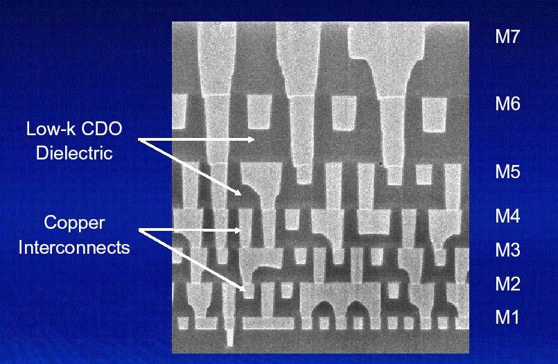
27 27
28 M3 M2 M1 p+ n+ n+ p+ p+ n+ n-well p-epi substrate 28
29 p-epi p+ substrate 29
30 SiO 2 p-epi p+ substrate Gate-oxide deposition 30
31 SiO 2 p-epi p+ substrate Photoresist 31
32 SiO 2 p-epi p+ substrate Mask 32
33 SiO 2 p-epi p+ substrate Expose (photolithography) 33
34 SiO 2 p-epi p+ substrate After photolithography 34
35 SiO 2 p-epi p+ substrate Remove mask 35
36 p-epi p+ substrate Etching 36
37 p-epi p+ substrate Etching 37
38 p-epi p+ substrate Oxide deposition 38
39 p-epi p+ substrate Photoresist 39
40 p-epi p+ substrate Mask 40
41 p-epi p+ substrate Photolithography 41
42 p-epi p+ substrate After photolithography 42
43 p-epi p+ substrate Etch 43
44 p+ (p-well) p-epi p+ substrate Doping 44
45 n+ (n-well) p+ (p-well) p-epi p+ substrate Doping 45
46 n+ (n-well) p+ (p-well) p-epi p+ substrate Poly 46
47 n+ (n-well) p+ (p-well) p-epi p+ substrate Etch 47
48 p+ p+ n+ n+ n+ (n-well) p+ (p-well) p-epi p+ substrate Doping 48
49 SiO 2 p+ p+ n+ n+ n+ (n-well) p+ (p-well) p-epi p+ substrate Oxide deposition 49
50 contact SiO 2 p+ p+ n+ n+ n+ (n-well) p+ (p-well) p-epi p+ substrate Contact 50
51 contact SiO 2 p+ p+ n+ n+ n+ (n-well) p+ (p-well) p-epi p+ substrate Metal 1 51
52 contact SiO 2 p+ p+ n+ n+ n+ (n-well) p+ (p-well) p-epi p+ substrate Via12 52
53 p-epi p+ substrate Chemical-mechanical-polishing (CMP) 53
54 54
EE 434 ASIC & Digital Systems
 EE 434 ASIC & Digital Systems Dae Hyun Kim EECS Washington State University Spring 2017 Course Website http://eecs.wsu.edu/~ee434 Themes Study how to design, analyze, and test a complex applicationspecific
+1 (479)
") Introduction to VLSI Design http://csce.uark.edu +1 (479) 575-6043 yrpeng@uark.edu Invention of the Transistor Vacuum tubes ruled in first half of 20th century Large, expensive, power-hungry, unreliable
Introduction to VLSI Design http://csce.uark.edu +1 (479) 575-6043 yrpeng@uark.edu Invention of the Transistor Vacuum tubes ruled in first half of 20th century Large, expensive, power-hungry, unreliable
2009 Spring CS211 Digital Systems & Lab 1 CHAPTER 3: TECHNOLOGY (PART 2)
") 1 CHAPTER 3: IMPLEMENTATION TECHNOLOGY (PART 2) Whatwillwelearninthischapter? we learn in this 2 How transistors operate and form simple switches CMOS logic gates IC technology FPGAs and other PLDs Basic
1 CHAPTER 3: IMPLEMENTATION TECHNOLOGY (PART 2) Whatwillwelearninthischapter? we learn in this 2 How transistors operate and form simple switches CMOS logic gates IC technology FPGAs and other PLDs Basic
Technology Timeline. Transistors ICs (General) SRAMs & DRAMs Microprocessors SPLDs CPLDs ASICs. FPGAs. The Design Warrior s Guide to.
 SRAMs & DRAMs Microprocessors SPLDs CPLDs ASICs. FPGAs. The Design Warrior s Guide to.") FPGAs 1 CMPE 415 Technology Timeline 1945 1950 1955 1960 1965 1970 1975 1980 1985 1990 1995 2000 Transistors ICs (General) SRAMs & DRAMs Microprocessors SPLDs CPLDs ASICs FPGAs The Design Warrior s Guide
FPGAs 1 CMPE 415 Technology Timeline 1945 1950 1955 1960 1965 1970 1975 1980 1985 1990 1995 2000 Transistors ICs (General) SRAMs & DRAMs Microprocessors SPLDs CPLDs ASICs FPGAs The Design Warrior s Guide
Jack Keil Wolf Lecture. ESE 570: Digital Integrated Circuits and VLSI Fundamentals. Lecture Outline. MOSFET N-Type, P-Type.
 ESE 570: Digital Integrated Circuits and VLSI Fundamentals Jack Keil Wolf Lecture Lec 3: January 24, 2019 MOS Fabrication pt. 2: Design Rules and Layout http://www.ese.upenn.edu/about-ese/events/wolf.php
ESE 570: Digital Integrated Circuits and VLSI Fundamentals
 ESE 570: Digital Integrated Circuits and VLSI Fundamentals Lec 3: January 24, 2019 MOS Fabrication pt. 2: Design Rules and Layout Penn ESE 570 Spring 2019 Khanna Jack Keil Wolf Lecture http://www.ese.upenn.edu/about-ese/events/wolf.php
Microelectronics, BSc course
 Microelectronics, BSc course MOS circuits: CMOS circuits, construction http://www.eet.bme.hu/~poppe/miel/en/14-cmos.pptx http://www.eet.bme.hu The abstraction level of our study: SYSTEM + MODULE GATE CIRCUIT
Physical Structure of CMOS Integrated Circuits
 Physical Structure of CMOS Integrated Circuits Dae Hyun Kim EECS Washington State University References John P. Uyemura, Introduction to VLSI Circuits and Systems, 2002. Chapter 3 Neil H. Weste and David
! Review: MOS IV Curves and Switch Model. ! MOS Device Layout. ! Inverter Layout. ! Gate Layout and Stick Diagrams. ! Design Rules. !
 ESE 570: Digital Integrated Circuits and VLSI Fundamentals Lec 3: January 21, 2017 MOS Fabrication pt. 2: Design Rules and Layout Lecture Outline! Review: MOS IV Curves and Switch Model! MOS Device Layout!
CMOS VLSI IC Design. A decent understanding of all tasks required to design and fabricate a chip takes years of experience
 CMOS VLSI IC Design A decent understanding of all tasks required to design and fabricate a chip takes years of experience 1 Commonly used keywords INTEGRATED CIRCUIT (IC) many transistors on one chip VERY
Physical Design of Digital Integrated Circuits (EN0291 S40) Sherief Reda Division of Engineering, Brown University Fall 2006
 Sherief Reda Division of Engineering, Brown University Fall 2006") Physical Design of Digital Integrated Circuits (EN0291 S40) Sherief Reda Division of Engineering, Brown University Fall 2006 Lecture 01: the big picture Course objective Brief tour of IC physical design
Physical Design of Digital Integrated Circuits (EN0291 S40) Sherief Reda Division of Engineering, Brown University Fall 2006 Lecture 01: the big picture Course objective Brief tour of IC physical design
Topic 3. CMOS Fabrication Process
 Topic 3 CMOS Fabrication Process Peter Cheung Department of Electrical & Electronic Engineering Imperial College London URL: www.ee.ic.ac.uk/pcheung/ E-mail: p.cheung@ic.ac.uk Lecture 3-1 Layout of a Inverter
Semiconductor Technology Academic Research Center An RTL-to-GDS2 Design Methodology for Advanced System LSI
 Semiconductor Technology Academic Research Center An RTL-to-GDS2 Design Methodology for Advanced System LSI Jan. 28. 2011 Nobuyuki Nishiguchi Semiconductor Technology Advanced Research Center (STARC) ASP-DAC
! Review: MOS IV Curves and Switch Model. ! MOS Device Layout. ! Inverter Layout. ! Gate Layout and Stick Diagrams. ! Design Rules. !
 ESE 570: Digital Integrated Circuits and VLSI Fundamentals Lec 3: January 21, 2016 MOS Fabrication pt. 2: Design Rules and Layout Lecture Outline! Review: MOS IV Curves and Switch Model! MOS Device Layout!
ESE 570: Digital Integrated Circuits and VLSI Fundamentals
 ESE 570: Digital Integrated Circuits and VLSI Fundamentals Lec 3: January 21, 2016 MOS Fabrication pt. 2: Design Rules and Layout Penn ESE 570 Spring 2016 Khanna Adapted from GATech ESE3060 Slides Lecture
CMOS Digital Integrated Circuits Lec 2 Fabrication of MOSFETs
 CMOS Digital Integrated Circuits Lec 2 Fabrication of MOSFETs 1 CMOS Digital Integrated Circuits 3 rd Edition Categories of Materials Materials can be categorized into three main groups regarding their
Sticks Diagram & Layout. Part II
 Sticks Diagram & Layout Part II Well and Substrate Taps Substrate must be tied to GND and n-well to V DD Metal to lightly-doped semiconductor forms poor connection called Shottky Diode Use heavily doped
ECE 5745 Complex Digital ASIC Design Topic 2: CMOS Devices
 ECE 5745 Complex Digital ASIC Design Topic 2: CMOS Devices Christopher Batten School of Electrical and Computer Engineering Cornell University http://www.csl.cornell.edu/courses/ece5950 Simple Transistor
Layout of a Inverter. Topic 3. CMOS Fabrication Process. The CMOS Process - photolithography (2) The CMOS Process - photolithography (1) v o.
 The CMOS Process - photolithography (1) v o.") Layout of a Inverter Topic 3 CMOS Fabrication Process V DD Q p Peter Cheung Department of Electrical & Electronic Engineering Imperial College London v i v o Q n URL: www.ee.ic.ac.uk/pcheung/ E-mail: p.cheung@ic.ac.uk
Layout of a Inverter Topic 3 CMOS Fabrication Process V DD Q p Peter Cheung Department of Electrical & Electronic Engineering Imperial College London v i v o Q n URL: www.ee.ic.ac.uk/pcheung/ E-mail: p.cheung@ic.ac.uk
Lecture 3, Handouts Page 1. Introduction. EECE 353: Digital Systems Design Lecture 3: Digital Design Flows, Simulation Techniques.
 Introduction EECE 353: Digital Systems Design Lecture 3: Digital Design Flows, Techniques Cristian Grecu grecuc@ece.ubc.ca Course web site: http://courses.ece.ubc.ca/353/ What have you learned so far?
MHz phase-locked loop
 SPECIFICATION 1 FEATURES 50 800 MHz phase-locked loop TSMC CMOS 65 nm Output frequency from 50 to 800 MHz Reference frequency from 4 to 30 MHz Power supply 1.2 V CMOS output Supported foundries: TSMC,
EC 1354-Principles of VLSI Design
 EC 1354-Principles of VLSI Design UNIT I MOS TRANSISTOR THEORY AND PROCESS TECHNOLOGY PART-A 1. What are the four generations of integrated circuits? 2. Give the advantages of IC. 3. Give the variety of
ESE370: Circuit-Level Modeling, Design, and Optimization for Digital Systems. Today. Variation. Variation. Process Corners.
 ESE370: Circuit-Level Modeling, Design, and Optimization for Digital Systems Day 13: October 3, 2012 Layout and Area Today Coping with Variation (from last time) Layout Transistors Gates Design rules Standard
Hot Topics and Cool Ideas in Scaled CMOS Analog Design
 Engineering Insights 2006 Hot Topics and Cool Ideas in Scaled CMOS Analog Design C. Patrick Yue ECE, UCSB October 27, 2006 Slide 1 Our Research Focus High-speed analog and RF circuits Device modeling,
FABRICATION OF CMOS INTEGRATED CIRCUITS. Dr. Mohammed M. Farag
 FABRICATION OF CMOS INTEGRATED CIRCUITS Dr. Mohammed M. Farag Outline Overview of CMOS Fabrication Processes The CMOS Fabrication Process Flow Design Rules Reference: Uyemura, John P. "Introduction to
PHYSICAL STRUCTURE OF CMOS INTEGRATED CIRCUITS. Dr. Mohammed M. Farag
 PHYSICAL STRUCTURE OF CMOS INTEGRATED CIRCUITS Dr. Mohammed M. Farag Outline Integrated Circuit Layers MOSFETs CMOS Layers Designing FET Arrays EE 432 VLSI Modeling and Design 2 Integrated Circuit Layers
ICE of silicon. [Roza] Computational efficiency [MOPS/W] 3DTV. Intrinsic computational efficiency.
![ICE of silicon. [Roza] Computational efficiency [MOPS/W] 3DTV. Intrinsic computational efficiency.](/thumbs/78/77184694.jpg "ICE of silicon. [Roza] Computational efficiency [MOPS/W] 3DTV. Intrinsic computational efficiency.") SoC Design ICE of silicon Computational efficiency [MOPS/W] 10 6 [Roza] 10 5 Intrinsic computational efficiency 3DTV 10 4 10 3 10 2 10 1 i386sx 601 604 604e microsparc Ultra sparc i486dx P5 Super sparc
SoC Design ICE of silicon Computational efficiency [MOPS/W] 10 6 [Roza] 10 5 Intrinsic computational efficiency 3DTV 10 4 10 3 10 2 10 1 i386sx 601 604 604e microsparc Ultra sparc i486dx P5 Super sparc
Disseny físic. Disseny en Standard Cells. Enric Pastor Rosa M. Badia Ramon Canal DM Tardor DM, Tardor
 Disseny físic Disseny en Standard Cells Enric Pastor Rosa M. Badia Ramon Canal DM Tardor 2005 DM, Tardor 2005 1 Design domains (Gajski) Structural Processor, memory ALU, registers Cell Device, gate Transistor
L15: VLSI Integration and Performance Transformations
 L15: VLSI Integration and Performance Transformations Acknowledgement: Materials in this lecture are courtesy of the following sources and are used with permission. Curt Schurgers J. Rabaey, A. Chandrakasan,
Interconnect/Via CONCORDIA VLSI DESIGN LAB
 Interconnect/Via 1 Delay of Devices and Interconnect 2 Reduction of the feature size Increase in the influence of the interconnect delay on system performance Skew The difference in the arrival times of
EE 330 Lecture 7. Design Rules. IC Fabrication Technology Part 1
 EE 330 Lecture 7 Design Rules IC Fabrication Technology Part 1 Review from Last Time Technology Files Provide Information About Process Process Flow (Fabrication Technology) Model Parameters Design Rules
Generation of Digital System Test Patterns Based on VHDL Simulations
 POSTER 2006, PRAGUE MAY 18 1 Generation of Digital System Test Patterns Based on VHDL Simulations Miljana SOKOLOVIĆ 1, Andy KUIPER 2 1 LEDA laboratory, aculty of Electronic Engineering, University of Niš,
30 ma flash LDO voltage regulator (output voltage 1.8 ± 0.2 V)
") SPECIFICATION 1 FEATURES Global Foundries CMOS 55 nm Low drop out Low current consumption Two modes operations: Normal, Economy Mode operation Bypass No discrete filtering capacitors required (cap-less
SPECIFICATION 1 FEATURES Global Foundries CMOS 55 nm Low drop out Low current consumption Two modes operations: Normal, Economy Mode operation Bypass No discrete filtering capacitors required (cap-less
Single Event Transient Effects on Microsemi ProASIC Flash-based FPGAs: analysis and possible solutions
 Single Event Transient Effects on Microsemi ProASIC Flash-based FPGAs: analysis and possible solutions L. Sterpone Dipartimento di Automatica e Informatica Politecnico di Torino, Torino, ITALY 1 Motivations
A 0.9 V Low-power 16-bit DSP Based on a Top-down Design Methodology
 UDC 621.3.049.771.14:621.396.949 A 0.9 V Low-power 16-bit DSP Based on a Top-down Design Methodology VAtsushi Tsuchiya VTetsuyoshi Shiota VShoichiro Kawashima (Manuscript received December 8, 1999) A 0.9
CS/ECE 5710/6710. Composite Layout
 CS/ECE 5710/6710 Introduction to Layout Inverter Layout Example Layout Design Rules Composite Layout Drawing the mask layers that will be used by the fabrication folks to make the devices Very different
Review: CMOS Logic Gates
 Review: CMOS Logic Gates INV Schematic NOR Schematic NAND Schematic + Vsg - pmos x x Vin Vout = Vin y + Vgs - nmos CMOS inverts functions CMOS Combinational Logic x g(x,y) = x + y use DeMorgan relations
Variation-Aware Design for Nanometer Generation LSI
 HIRATA Morihisa, SHIMIZU Takashi, YAMADA Kenta Abstract Advancement in the microfabrication of semiconductor chips has made the variations and layout-dependent fluctuations of transistor characteristics
Lecture 0: Introduction
 Lecture 0: Introduction Introduction Integrated circuits: many transistors on one chip. Very Large Scale Integration (VLSI): bucketloads! Complementary Metal Oxide Semiconductor Fast, cheap, low power
! MOS Device Layout. ! Inverter Layout. ! Gate Layout and Stick Diagrams. ! Design Rules. ! Standard Cells. ! CMOS Process Enhancements
 EE 570: igital Integrated Circuits and VLI Fundamentals Lec 3: January 18, 2018 MO Fabrication pt. 2: esign Rules and Layout Lecture Outline! MO evice Layout! Inverter Layout! Gate Layout and tick iagrams!
420 Intro to VLSI Design
 Dept of Electrical and Computer Engineering 420 Intro to VLSI Design Lecture 0: Course Introduction and Overview Valencia M. Joyner Spring 2005 Getting Started Syllabus About the Instructor Labs, Problem
EE141-Fall 2009 Digital Integrated Circuits
 EE141-Fall 2009 Digital Integrated Circuits Lecture 2 Integrated Circuit Basics: Manufacturing and Cost 1 1 Administrative Stuff Discussions start this Friday We have a third GSI Richie Przybyla, rjp@eecs
Engr354: Digital Logic Circuits
 Engr354: Digital Logic Circuits Chapter 3: Implementation Technology Curtis Nelson Chapter 3 Overview In this chapter you will learn about: How transistors are used as switches; Integrated circuit technology;
EE4800 CMOS Digital IC Design & Analysis. Lecture 1 Introduction Zhuo Feng
 EE4800 CMOS Digital IC Design & Analysis Lecture 1 Introduction Zhuo Feng 1.1 Prof. Zhuo Feng Office: EERC 730 Phone: 487-3116 Email: zhuofeng@mtu.edu Class Website http://www.ece.mtu.edu/~zhuofeng/ee4800fall2010.html
2.5D & 3D Package Signal Integrity A Paradigm Shift
 2.5D & 3D Package Signal Integrity A Paradigm Shift Nozad Karim Technology & Platform Development November, 2011 Enabling a Microelectronic World Content Traditional package signal integrity vs. 2.5D/3D
Timing analysis can be done right after synthesis. But it can only be accurately done when layout is available
 Timing Analysis Lecture 9 ECE 156A-B 1 General Timing analysis can be done right after synthesis But it can only be accurately done when layout is available Timing analysis at an early stage is not accurate
AN EFFICIENT APPROACH TO MINIMIZE POWER AND AREA IN CARRY SELECT ADDER USING BINARY TO EXCESS ONE CONVERTER
 AN EFFICIENT APPROACH TO MINIMIZE POWER AND AREA IN CARRY SELECT ADDER USING BINARY TO EXCESS ONE CONVERTER K. RAMAMOORTHY 1 T. CHELLADURAI 2 V. MANIKANDAN 3 1 Department of Electronics and Communication
Digital Integrated Circuits Perspectives. Administrivia
 Lecture 30 Perspectives Administrivia Final on Friday December 14, 2001 8 am Location: 180 Tan Hall Topics all what was covered in class. Review Session - TBA Lab and hw scores to be posted on the web
Lecture 1. Tinoosh Mohsenin
 Lecture 1 Tinoosh Mohsenin Today Administrative items Syllabus and course overview Digital systems and optimization overview 2 Course Communication Email Urgent announcements Web page http://www.csee.umbc.edu/~tinoosh/cmpe650/
L15: VLSI Integration and Performance Transformations
 L15: VLSI Integration and Performance Transformations Average Cost of one transistor Acknowledgement: 10 1 0.1 0.01 0.001 0.0001 0.00001 $ 0.000001 Gordon Moore, Keynote Presentation at ISSCC 2003 0.0000001
EE 5327 VLSI Design Laboratory. Lab 7 (1 week) - Power Optimization
 - Power Optimization") EE 5327 VLSI Design Laboratory Lab 7 (1 week) - Power Optimization PURPOSE: The purpose of this lab is to introduce design optimization for power in addition to area and speed. We will be using Design
EE 5327 VLSI Design Laboratory Lab 7 (1 week) - Power Optimization PURPOSE: The purpose of this lab is to introduce design optimization for power in addition to area and speed. We will be using Design
18nm FinFET. Lecture 30. Perspectives. Administrivia. Power Density. Power will be a problem. Transistor Count
 18nm FinFET Double-gate structure + raised source/drain Lecture 30 Perspectives Gate Silicon Fin Source BOX Gate X. Huang, et al, 1999 IEDM, p.67~70 Drain Si fin - Body! I d [ua/um] 400-1.50 V 350 300-1.25
EECS150 - Digital Design Lecture 19 CMOS Implementation Technologies. Recap and Outline
 EECS150 - Digital Design Lecture 19 CMOS Implementation Technologies Oct. 31, 2013 Prof. Ronald Fearing Electrical Engineering and Computer Sciences University of California, Berkeley (slides courtesy
Fixing Antenna Problem by Dynamic Diode Dropping and Jumper Insertion
 Fixing Antenna Problem by Dynamic Dropping and Jumper Insertion Peter H. Chen and Sunil Malkani Chun-Mou Peng James Lin TeraLogic, Inc. International Tech. Univ. National Semi. Corp. 1240 Villa Street
Mixed Signal Virtual Components COLINE, a case study
 Mixed Signal Virtual Components COLINE, a case study J.F. POLLET - DOLPHIN INTEGRATION Meylan - FRANCE http://www.dolphin.fr Overview of the presentation Introduction COLINE, an example of Mixed Signal
EECS150 - Digital Design Lecture 15 - CMOS Implementation Technologies. Overview of Physical Implementations
 EECS150 - Digital Design Lecture 15 - CMOS Implementation Technologies Mar 12, 2013 John Wawrzynek Spring 2013 EECS150 - Lec15-CMOS Page 1 Overview of Physical Implementations Integrated Circuits (ICs)
EECS150 - Digital Design Lecture 9 - CMOS Implementation Technologies
 EECS150 - Digital Design Lecture 9 - CMOS Implementation Technologies Feb 14, 2012 John Wawrzynek Spring 2012 EECS150 - Lec09-CMOS Page 1 Overview of Physical Implementations Integrated Circuits (ICs)
EECS 427 Lecture 21: Design for Test (DFT) Reminders
 Reminders") EECS 427 Lecture 21: Design for Test (DFT) Readings: Insert H.3, CBF Ch 25 EECS 427 F09 Lecture 21 1 Reminders One more deadline Finish your project by Dec. 14 Schematic, layout, simulations, and final
EECS 427 Lecture 21: Design for Test (DFT) Readings: Insert H.3, CBF Ch 25 EECS 427 F09 Lecture 21 1 Reminders One more deadline Finish your project by Dec. 14 Schematic, layout, simulations, and final
On Chip Active Decoupling Capacitors for Supply Noise Reduction for Power Gating and Dynamic Dual Vdd Circuits in Digital VLSI
 ELEN 689 606 Techniques for Layout Synthesis and Simulation in EDA Project Report On Chip Active Decoupling Capacitors for Supply Noise Reduction for Power Gating and Dynamic Dual Vdd Circuits in Digital
Low Power Radiation Tolerant CMOS Design using Commercial Fabrication Processes
 Low Power Radiation Tolerant CMOS Design using Commercial Fabrication Processes Amir Hasanbegovic (amirh@ifi.uio.no) Nanoelectronics Group, Dept. of Informatics, University of Oslo November 5, 2010 Overview
ASICs Concept to Product
 ASICs Concept to Product Synopsis This course is aimed to provide an opportunity for the participant to acquire comprehensive technical and business insight into the ASIC world. As most of these aspects
Interconnect-Power Dissipation in a Microprocessor
 4/2/2004 Interconnect-Power Dissipation in a Microprocessor N. Magen, A. Kolodny, U. Weiser, N. Shamir Intel corporation Technion - Israel Institute of Technology 4/2/2004 2 Interconnect-Power Definition
1. Introduction. Institute of Microelectronic Systems. Status of Microelectronics Technology. (nm) Core voltage (V) Gate oxide thickness t OX
 Core voltage (V) Gate oxide thickness t OX") Threshold voltage Vt (V) and power supply (V) 1. Introduction Status of s Technology 10 5 2 1 0.5 0.2 0.1 V dd V t t OX 50 20 10 5 2 Gate oxide thickness t OX (nm) Future VLSI chip 2005 2011 CMOS feature
Threshold voltage Vt (V) and power supply (V) 1. Introduction Status of s Technology 10 5 2 1 0.5 0.2 0.1 V dd V t t OX 50 20 10 5 2 Gate oxide thickness t OX (nm) Future VLSI chip 2005 2011 CMOS feature
EE 434 Lecture 2. Basic Concepts
 EE 434 Lecture 2 Basic Concepts Review from Last Time Semiconductor Industry is One of the Largest Sectors in the World Economy and Growing All Initiatives Driven by Economic Opportunities and Limitations
Electronic Design Automation at Transistor Level by Ricardo Reis. Preamble
 1 Electronic Design Automation at Transistor Level by Ricardo Reis Preamble 1 Quintillion of Transistors 90 65 45 32 NM Electronic Design Automation at Transistor Level Ricardo Reis Universidade Federal
ASIC Computer-Aided Design Flow ELEC 5250/6250
 ASIC Computer-Aided Design Flow ELEC 5250/6250 ASIC Design Flow ASIC Design Flow DFT/BIST & ATPG Synthesis Behavioral Model VHDL/Verilog Gate-Level Netlist Verify Function Verify Function Front-End Design
Low Power Design Methods: Design Flows and Kits
 JOINT ADVANCED STUDENT SCHOOL 2011, Moscow Low Power Design Methods: Design Flows and Kits Reported by Shushanik Karapetyan Synopsys Armenia Educational Department State Engineering University of Armenia
Announcements. Advanced Digital Integrated Circuits. Project proposals due today. Homework 1. Lecture 8: Gate delays,
 EE4 - Spring 008 Advanced Digital Integrated Circuits Lecture 8: Gate delays, Variability Announcements Project proposals due today Title Team members ½ page ~5 references Post it on your EECS web page
Introduction to Digital VLSI Design מבוא לתכנון VLSI ספרתי
 Design מבוא לתכנון VLSI ספרתי Extraction Lecturer: Gil Rahav Semester B, EE Dept. BGU. Freescale Semiconductors Israel Slide 1 Extraction Extraction is a process of creating electrical representation (R&C)
Digital Systems Design
 Digital Systems Design Digital Systems Design and Test Dr. D. J. Jackson Lecture 1-1 Introduction Traditional digital design Manual process of designing and capturing circuits Schematic entry System-level
2 MARK QUESTIONS & ANSWERS UNIT1-MOS TRANSISTOR PRINCIPLE
 2 MARK QUESTIONS & ANSWERS UNIT1-MOS TRANSISTOR PRINCIPLE 1.What are four generations of Integration Circuits? _ SSI (Small Scale Integration) _ MSI (Medium Scale Integration) _ LSI (Large Scale Integration)
Layers. Layers. Layers. Transistor Manufacturing COMP375 1
 Layers VLSI COMP370 Intro to Computer Architecture t Applications Middleware other CS classes High level languages Machine Language Microcode Logic circuits Gates Transistors Silicon structures Layers
EE434 ASIC & Digital Systems
 EE434 ASIC & Digital Systems Partha Pande School of EECS Washington State University pande@eecs.wsu.edu Spring 2015 Dae Hyun Kim daehyun@eecs.wsu.edu 1 Lecture 4 More on CMOS Gates Ref: Textbook chapter
Very Large Scale Integration (VLSI)
") Very Large Scale Integration (VLSI) Lecture 6 Dr. Ahmed H. Madian Ah_madian@hotmail.com Dr. Ahmed H. Madian-VLSI 1 Contents Array subsystems Gate arrays technology Sea-of-gates Standard cell Macrocell
Very Large Scale Integration (VLSI) Lecture 6 Dr. Ahmed H. Madian Ah_madian@hotmail.com Dr. Ahmed H. Madian-VLSI 1 Contents Array subsystems Gate arrays technology Sea-of-gates Standard cell Macrocell
LSI Design Flow Development for Advanced Technology
 LSI Design Flow Development for Advanced Technology Atsushi Tsuchiya LSIs that adopt advanced technologies, as represented by imaging LSIs, now contain 30 million or more logic gates and the scale is beginning
CS250 VLSI Systems Design. Lecture 3: Physical Realities: Beneath the Digital Abstraction, Part 1: Timing
 CS250 VLSI Systems Design Lecture 3: Physical Realities: Beneath the Digital Abstraction, Part 1: Timing Fall 2010 Krste Asanovic, John Wawrzynek with John Lazzaro and Yunsup Lee (TA) What do Computer
Chapter 3 CMOS processing technology (II)
") Chapter 3 CMOS processing technology (II) Twin-tub CMOS process 1. Provide separate optimization of the n-type and p-type transistors 2. Make it possible to optimize "Vt", "Body effect", and the "Gain"
Chapter 3 CMOS processing technology (II) Twin-tub CMOS process 1. Provide separate optimization of the n-type and p-type transistors 2. Make it possible to optimize "Vt", "Body effect", and the "Gain"
Homework 10 posted just for practice. Office hours next week, schedule TBD. HKN review today. Your feedback is important!
 EE141 Fall 2005 Lecture 26 Memory (Cont.) Perspectives Administrative Stuff Homework 10 posted just for practice No need to turn in Office hours next week, schedule TBD. HKN review today. Your feedback
The backend duplication method
 The backend duplication method - A Leakage-Proof Place-and and-route Strategy for Secured ASICs - CHES Workshop August 30th September 1st 2005 Edinburgh, Scotland, UK. Sylvain GUILLEY (*), Philippe HOOGVORST
Reference. Wayne Wolf, FPGA-Based System Design Pearson Education, N Krishna Prakash,, Amrita School of Engineering
 FPGA Fabrics Reference Wayne Wolf, FPGA-Based System Design Pearson Education, 2004 CPLD / FPGA CPLD Interconnection of several PLD blocks with Programmable interconnect on a single chip Logic blocks executes
Lecture #2 Solving the Interconnect Problems in VLSI
 Lecture #2 Solving the Interconnect Problems in VLSI C.P. Ravikumar IIT Madras - C.P. Ravikumar 1 Interconnect Problems Interconnect delay has become more important than gate delays after 130nm technology
EE 330 Lecture 7. Design Rules
 EE 330 Lecture 7 Design Rules Last time: Response time of logic gates A Y C L t R C HL SWn L t R C LH SWp L C L proportional to #gates driven to avg input cap of gates R SW proportional length/width Last
12-Bit 1-channel 4 MSPS ADC
 SPECIFICATION 1 FEATURES 12-Bit 1-channel 4 MSPS ADC TSMC CMOS 65 nm Resolution 12 bit Single power supplies for digital and analog parts (2.5 V) Sampling rate up to 4 MSPS Standby mode (current consumption
EECS 151/251A Spring 2019 Digital Design and Integrated Circuits. Instructors: Wawrzynek. Lecture 8 EE141
 EECS 151/251A Spring 2019 Digital Design and Integrated Circuits Instructors: Wawrzynek Lecture 8 EE141 From the Bottom Up IC processing CMOS Circuits (next lecture) EE141 2 Overview of Physical Implementations
Power-Delivery Network in 3D ICs: Monolithic 3D vs. Skybridge 3D CMOS
 -Delivery Network in 3D ICs: Monolithic 3D vs. Skybridge 3D CMOS Jiajun Shi, Mingyu Li and Csaba Andras Moritz Department of Electrical and Computer Engineering University of Massachusetts, Amherst, MA,
Design Quality Trade-Off Studies for 3-D ICs Built With Sub-Micron TSVs and Future Devices
 240 IEEE JOURNAL ON EMERGING AND SELECTED TOPICS IN CIRCUITS AND SYSTEMS, VOL. 2, NO. 2, JUNE 2012 Design Quality Trade-Off Studies for 3-D ICs Built With Sub-Micron TSVs and Future Devices Dae Hyun Kim,
Automated Place and Route Methodologies. For Multi-project Test Chips. Christopher Lieb
 Automated Place and Route Methodologies For Multi-project Test Chips by Christopher Lieb A Thesis Presented in Partial Fulfillment of the Requirements for the Degree Master of Science Approved April 2015
Digital Integrated Circuits 1: Fundamentals
 Digital Integrated Circuits 1: Fundamentals Atsushi Takahashi Department of Information and Communications Engineering School of Engineering Tokyo Institute of Technology 1 VLSI and Computer System VLSI
50 MSPS 2-bit 2-channel special ADC
 SPECIFICATION 1 FEATURES 50 MSPS 2-bit 2-channel special ADC UMC CMOS 180 nm Resolution 2 bit 2-channel Adjustment of threshold levels Adjustment of dc level of thresholds scale Analog supply voltage 3.3
Signal Integrity Design of TSV-Based 3D IC
 Signal Integrity Design of TSV-Based 3D IC October 24, 21 Joungho Kim at KAIST joungho@ee.kaist.ac.kr http://tera.kaist.ac.kr 1 Contents 1) Driving Forces of TSV based 3D IC 2) Signal Integrity Issues
Fundamentals of Integrated Circuit Design
 1. Definitions Integrated circuits Fundamentals of Integrated Circuit Design An integrated circuit (IC) is formed by components and interconnections that are fabricated on a single silicon piece of semiconductor,
Digital Design: An Embedded Systems Approach Using VHDL
 Digital Design: An Embedded Systems Approach Using Chapter 6 Implementation Fabrics Portions of this work are from the book, Digital Design: An Embedded Systems Approach Using, by Peter J. Ashenden, published
UT90nHBD Hardened-by-Design (HBD) Standard Cell Data Sheet February
 Standard Cell Data Sheet February") Semicustom Products UT90nHBD Hardened-by-Design (HBD) Standard Cell Data Sheet February 2018 www.cobham.com/hirel The most important thing we build is trust FEATURES Up to 50,000,000 2-input NAND equivalent
Semicustom Products UT90nHBD Hardened-by-Design (HBD) Standard Cell Data Sheet February 2018 www.cobham.com/hirel The most important thing we build is trust FEATURES Up to 50,000,000 2-input NAND equivalent
Logic Synthesis. Logic synthesis transforms RTL code into a gate-level netlist. RTL Verilog converted into Structural Verilog
 Logic Synthesis Logic synthesis transforms RTL code into a gate-level netlist RTL Verilog converted into Structural Verilog Logic Synthesis - The process and steps Translation Check RTL for valid syntax
CS 6135 VLSI Physical Design Automation Fall 2003
 CS 6135 VLSI Physical Design Automation Fall 2003 1 Course Information Class time: R789 Location: EECS 224 Instructor: Ting-Chi Wang ( ) EECS 643, (03) 5742963 tcwang@cs.nthu.edu.tw Office hours: M56R5
IFSIN. WEB PAGE Fall ://weble.upc.es/ifsin/
 IFSIN IMPLEMENTACIÓ FÍSICA DE SISTEMES INTEGRATS NANOMÈTRICS IMPLEMENTACIÓN N FÍSICA F DE SISTEMAS INTEGRADOS NANOMÉTRICOS PHYSICAL IMPLEMENTATION OF NANOMETER INTEGRATED SYSTEMS Fall 2008 Prof. Xavier
Design Methodologies. Digital Integrated Circuits A Design Perspective. Jan M. Rabaey Anantha Chandrakasan Borivoje Nikolic.
 Digital Integrated Circuits A Design Perspective Jan M. Rabaey Anantha Chandrakasan Borivoje Nikolic Design Methodologies December 10, 2002 L o g i c T r a n s i s t o r s p e r C h i p ( K ) 1 9 8 1 1
Learning Outcomes. Spiral 2 8. Digital Design Overview LAYOUT
 2-8.1 2-8.2 Spiral 2 8 Cell Mark Redekopp earning Outcomes I understand how a digital circuit is composed of layers of materials forming transistors and wires I understand how each layer is expressed as
ELEC Digital Logic Circuits Fall 2015 Delay and Power
 ELEC - Digital Logic Circuits Fall 5 Delay and Power Vishwani D. Agrawal James J. Danaher Professor Department of Electrical and Computer Engineering Auburn University, Auburn, AL 36849 http://www.eng.auburn.edu/~vagrawal
Chapter12. Chip Assembly. Figure 12.1: Starting schematic showing the three connected modules
 Chapter12 Chip Assembly Figure 12.1: Starting schematic showing the three connected modules 236 CHAPTER 12: Chip Assembly Figure 12.2: The Gen From Source dialog box 237 Figure 12.3: Initial layout before