ME 111: Engineering Drawing
|
|
|
- Ernest Marshall Garrett
- 6 years ago
- Views:
Transcription
1 ME 111: Engineering Drawing Lecture # 01 Introduction For more detail, visit Indian Institute of Technology Guwahati Guwahati
2 Syllabus 1. Importance of engineering drawing; Drawing techniques 2. Manual drawing instruments and their uses Drawing board; Minidrafter; Set squares; Drawing instrument box; Scales; Protractor; French curves; Drawing papers; Drawing pencils; Eraser; Drawing pins/clips; Sand paper block; Duster. 3. Conventions - ISO and BIS; Layout of drawing sheets; Border lines; Title block; Folding of drawing sheets; Lines, lettering and dimensioning. 4. Scales Plane, diagonal and vernier 5. Curves used in engineering practice: 6. Orthographic projection Theory of projection 2
3 7. Projection of points 8. Projection of straight lines 9. Projection of planes 10.Projection of solids 11. Auxiliary projections 12.Sections of solids 13. Development of surfaces 14.Intersections of solids 15.Isometric projections 3
4 Books/references 1. Dhananjay A Jolhe, Engineering drawing, TMH, M.B. Shah and B.C. Rana, Engineering Drawing, Pearsonson, N D Bhatt and V M Panchal, Engineering Drawing, 43rd edition, Charator Publishing House, T E French, C J Vierck and R J Foster, Graphic Science and Design, 4th edition, McGraw Hill, W J Luzadder and J M Duff, Fundamentals of Engineering Drawing, 11th edition, Prentice-Hall of India, K Venugpoal, Engineering Drawing and Graphics, 3nd edition, New Age International,
5 Scheme of evaluation Practical Assignments : (35%) Mid Semester Examination : (25%) End Semester Examination : (40%) Note to the students 1. Practical assignments are to be completed in the Drawing Hall during the respective practice period itself. 2. No make-up class for the completion of the incomplete assignments. 3. Only one make-up class for a missed class, that too only under medical ground. Students having attendance (lecture + tutorial) less than 75%, or for both lecture and tutorial independently will be debarred from appearing in the end semester examination. 4. No entry to the lecture hall 5 minutes after the start of the class. 5
6 Slot 9.00 AM AM 2.00 PM-5.00 PM Day Group /Tutor Student Roll Nos. Group /Tutor Student Roll Nos. Mon. Tue. Wed. Thur. Fri. Instructors: Prof. P.S. Robi & Dr. P.K. Ghosh Tutorial Groups and Tutors L8-A Dr. Sreeja. P L8-B Dr. Pankaj Biswas L6-A Dr. Pallab Ghosh L6-B Dr. A.K. Maurya L9-A Dr. A. K. D. Mahapatra L9-B Dr. R. Bhattacharjee L7-A Dr. T. Lyngdoh L7-B Dr. Vimal Katiyar L10-A Dr. A. Dey L10-B Dr. Prakash Kotecha L3-A Dr. Amaresh Dalal L3-B Dr. Nanda Kishore L1-A Dr. B. Singh L1-B Dr. P. Muthukumar L4-A Dr. Atanu Banerjee L4-B Dr. Mihir Purkait L2-A Dr. Arnab Kr. De L2-B Dr. R. Upalluri L5-A Prof. S.K. Dwivedy L5-B Dr. Anil Verma
7 ENGINEERING DRAWING Graphical means of expression of technical details without the barrier of a language. Universal language for Engineers 7
8 What will you learn from this course? How to communicate technical information. Visualization the ability to mentally understand visual information. Graphics theory geometry and projection techniques used for preparation of drawings. Standards set of rules for preparation of technical drawings. Conventions commonly accepted practices in technical drawings. Tools devices used to create technical drawings and models. Applications the various uses for technical drawings. 8
9 Graphic language: mode of communication through SKETCHES Drawing: graphical representation of an OBJECT Engineering Drawing Drawing of an object contains all the necessary information, required for the construction/fabrication of the object, like actual shape, accurate sizes, manufacturing methods, materials to be used etc., 9
10 List of tools required for the drawing practice session Sl. No. Item Quantity 1 Mini-drafter (or T-Square) 1 2 Engineering Drawing Box 1 3 French curves 1 set 4 Set-square 1 set 5 Protractor 1 6 Drawing Clip 1 set 7 Lead pencil/clutch pencil Lead (HB, H & 2H) 1 each set 9 Eraser 1 10 Sand paper/cello tape 1 11 Blade / pencil sharpener 1 12 Drawing Sheet 1 per session Students without Engineering Drawing Box will not be allowed to attend the practical session. School Instrument box is not allowed. 10


11 Mini-drafter 11

12 Mini-drafter fixed on a drawing table 12
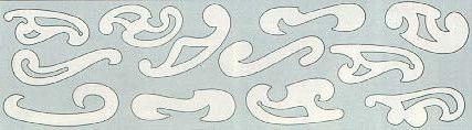
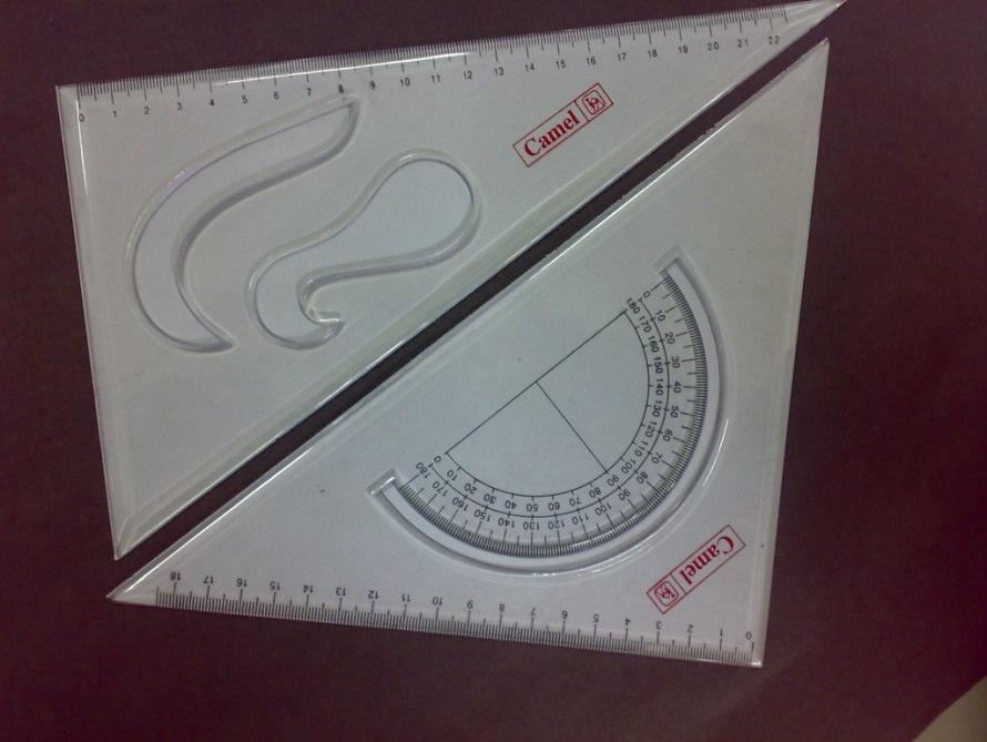
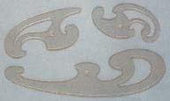

13 Set-square Drawing Clips French Curves 13
14 Scale set 14
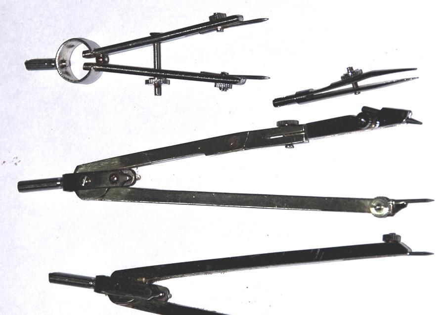
15 Engineering Drawing Box 15
16 16

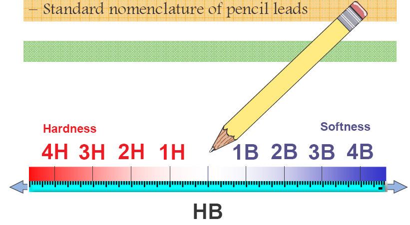
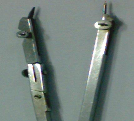
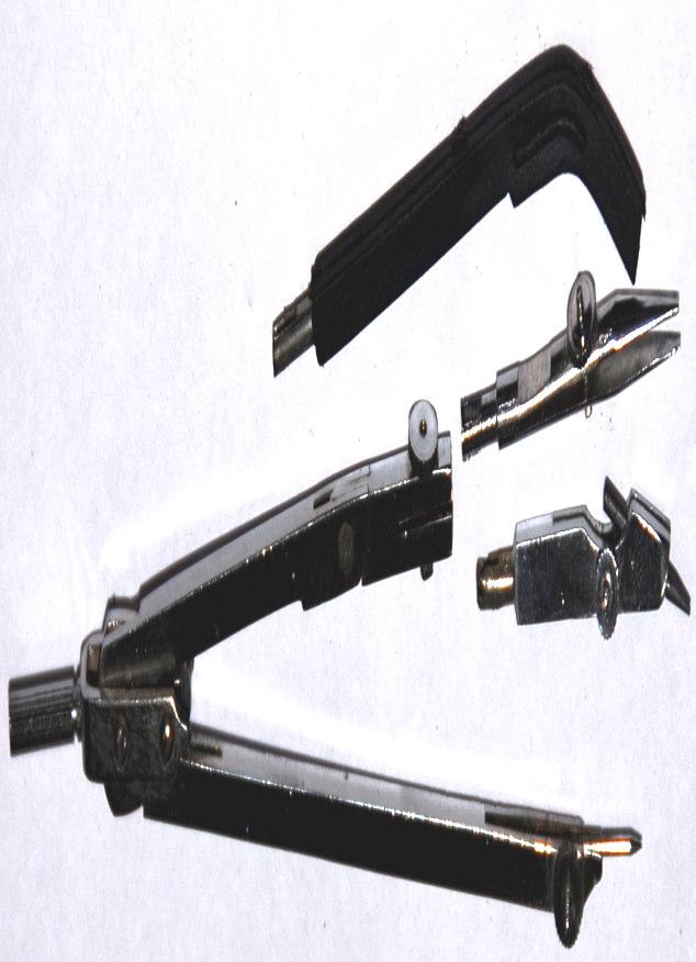
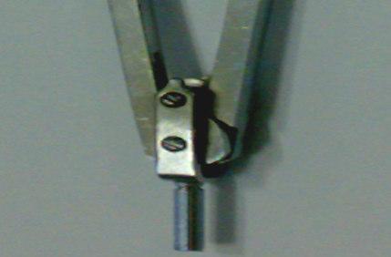
17 Pencils 17
18 Dimensions of Engineer s Drawing Boards Designation Length x Width (mm) Recommended for use with sheet sizes D x 1000 A0 D x 700 A1 D2 700 x 500 A2 D3 500 x 500 A3 D0 and D1 for drawing offices, for students use D2 18
19 Standard sizes of drawing sheets as per BIS Designation Size (mm) A0 841 x 1189 A1 594 x 841 A2 420 x 594 A3 297 x 420 A4 210 x
20 Drawing Sheet Sizes 20
21 Drawing sheet Layout 21

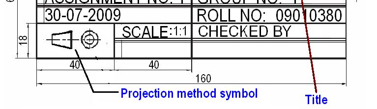
22 Title Block 22
23 LINES AND LETTERING* LINES Lines are the basic feature of a drawing. A line may be straight, curved, continuous, segmented, thin, thick, etc., each having its own specific sense. Line strokes refer to the directions of drawing straight and curved lines *standard given in BIS : SP-46, 2003 Available in //intranet.iitg.ernet.in/bis_asp/start.shtml 8/11/
24 Line Strokes Vertical and inclined lines are drawn from top to bottom, horizontal lines are drawn from left to right. Curved lines are drawn from left to right or top to bottom. 8/11/
25 Illustration Line types Application Thick Outlines, visible edges, surface boundaries of objects, margin lines Continuous thin Dimension lines, extension lines, section lines leader or pointer lines, construction lines, boarder lines Continuous thin wavy Short break lines or irregular boundary lines drawn freehand Continuous thin with zig-zag Long break lines Short dashes, gap 1, length 3 mm Invisible or interior surfaces 8/11/
26 Line types Illustration Short dashes Long chain thick at end and thin elsewhere Application Center lines, locus lines Alternate long and short dashes in a proportion of 6:1, Cutting plane lines Continuous thick border line Border 8/11/
27 Uses of different types of lines in a given drawing 8/11/
28 Units of Measurement International systems of units (SI) which is based on the meter. Millimeter (mm) - The common SI unit of measure on engineering drawing. Individual identification of linear units is not required if all dimensions on a drawing are in the same unit (mm). The drawing shall however contain a note: ALL DIMENSIONS ARE IN MM. (Bottom left corner outside the title box) 8/11/
29 Dimensioning Indicating on a drawing, the size of the object and other details essential for its construction and function, using lines, numerals, symbols, notes, etc. Dimensions indicated on a drawing should be those that are essential for the production, inspection and functioning of the object. Dimensions indicated should not be mistaken as those that are required to make the drawing of an object. 8/11/2011
30 An example 30
31 Extension line a thin, solid line perpendicular to a dimension line, indicating which feature is associated with the dimension. Visible gap there should be a visible gap of 1.5 mm between the feature s corners and the end of the extension line. 8/11/
32 Leader line A thin, solid line used to indicate the feature with which a dimension, note, or symbol is associated. Generally a straight line drawn at an angle that is neither horizontal nor vertical. Terminated with an arrow touching the part or detail. On the end opposite the arrow, the leader line will have a short, horizontal shoulder. Text is extended from this shoulder such that the text height is centered with the shoulder line. 8/11/


33 Arrows 3 mm wide and should be 1/3 rd as wide as they are long - symbols placed at the end of dimension lines to show the limits of the dimension. Arrows are uniform in size and style, regardless of the size of the drawing. 8/11/

34 Spacing of Dimensions 34

35 Placing of Dimensions Orientation of Dimensioning Text 35
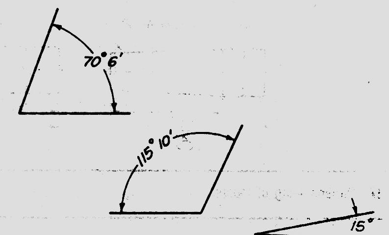

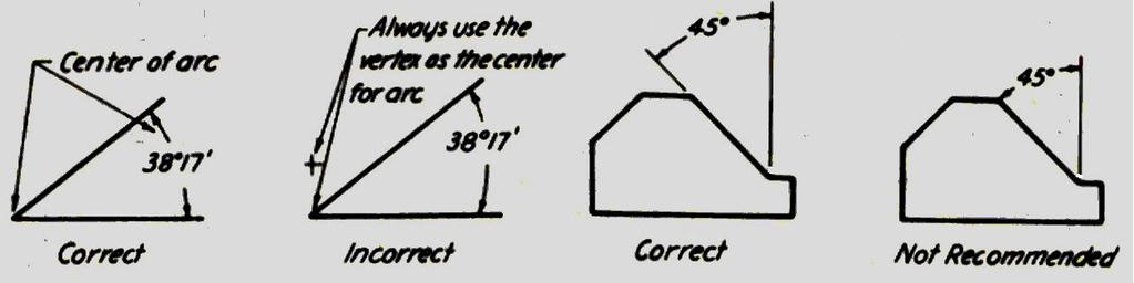
36 Dimensioning of angles 8/11/
37 Dimensioning of Circular Features A circle should be dimensioned by giving its diameter instead of radius. The dimension indicating a diameter should always be preceded by the symbol ø, 8/11/


38 Dimensioning a Length Depends on Available Space 38


39 Dimensioning Radii Arcs of Circle Precede with R to distinguish from length 39
40 RULES OF DIMENSIONING 1. Between any two extension lines, there must be one and only one dimension line bearing one dimension. 2. As far as possible, all the dimensions should be placed outside the views. Inside dimensions are preferred only if they are clearer and more easily readable. 3. All the dimensions on a drawing must be shown using either Aligned System or Unidirectional System. In no case should, the two systems be mixed on the same drawing. 4. The same unit of length should be used for all the dimensions on a drawing. The unit should not be written after each dimension, but a note mentioning the unit should be placed below the drawing. 5. Dimension lines should not cross each other. Dimension lines should also not cross any other lines of the object. 6. All dimensions must be given. 7. Each dimension should be given only once. No dimension should be redundant. 8/11/2011
41 8. Do not use an outline or a centre line as a dimension line. A centre line may be extended to serve as an extension line. 9. Avoid dimensioning hidden lines. 10. For dimensions in series, adopt any one of the following ways. i. Chain dimensioning (Continuous dimensioning) All the dimensions are aligned in such a way that an arrowhead of one dimension touches tip-to-tip the arrowhead of the adjacent dimension. The overall dimension is placed outside the other smaller dimensions. ii. Parallel dimensioning (Progressive dimensioning) All the dimensions are shown from a common reference line. Obviously, all these dimensions share a common extension line. This method is adopted when dimensions have to be established from a particular datum surface iii. Combined dimensioning When both the methods, i.e., chain dimensioning and parallel dimensioning are used on the same drawing, the method of dimensioning is called combined dimensioning. 8/11/2011
42 Dimensioning Guidelines Avoid crossing extension lines Multiple extension line crossings may be confused for the outside corner of the part. 42
43 Single stroke refers to the thickness obtained in one stroke of a pencil or ink pen. It does not mean that the pencil or pen should not be lifted while completing a particular letter. Lettering types Lettering A Height of the capital letter is divided into 14 equal parts Lettering B Height of the capital letter is divided into 10 equal parts 8/11/
44 Specifications of A -Type Lettering Specifications Value Size (mm) Capital letter height h Lowercase letter height a = (5/7)h Thickness of lines b = (1/14)h Spacing between characters c = (1/7)h Min. spacing b/n words d = (3/7)h Min. spacing b/n baselines e = (10/7)h Ratio of height to width varies, but in most cases is 6:5
45 8/11/
(As per New Revised Syllabus of Anna University) Department of Mechanical Engineering. SATHYABAMA UNIVERSITY Jeppiaar Nagar, Chennai
 Department of Mechanical Engineering. SATHYABAMA UNIVERSITY Jeppiaar Nagar, Chennai") (1*,1((5,1* *5$3+,&6 (As per New Revised Syllabus of Anna University) Dr. S.RAMACHANDRAN, M.E., Ph.D. Professor & Head K. PANDIAN, M.E., E.V.V.RAMANAMURTHY, M.Tech., R. DEVARAJ, M.E., Associate Professors
(1*,1((5,1* *5$3+,&6 (As per New Revised Syllabus of Anna University) Dr. S.RAMACHANDRAN, M.E., Ph.D. Professor & Head K. PANDIAN, M.E., E.V.V.RAMANAMURTHY, M.Tech., R. DEVARAJ, M.E., Associate Professors
DRAWING INSTRUMENTS AND THEIR USES
 Chapter - 1A DRAWING INSTRUMENTS AND THEIR USES Drawing Instruments are used to prepare neat and accurate Drawings. To a greater extent, the accuracy of the Drawings depend on the quality of instruments
Multiview Drawing. Definition: Graphical representation of a 3- dimensional object on one plane (sheet of paper) using two or more views.
 using two or more views.") Multiview Drawing Definition: Graphical representation of a 3- dimensional object on one plane (sheet of paper) using two or more views. Multiview Drawing Another name for multiview drawing is orthographic
Multiview Drawing Definition: Graphical representation of a 3- dimensional object on one plane (sheet of paper) using two or more views. Multiview Drawing Another name for multiview drawing is orthographic
Engineering Graphics Essentials with AutoCAD 2015 Instruction
 Kirstie Plantenberg Engineering Graphics Essentials with AutoCAD 2015 Instruction Text and Video Instruction Multimedia Disc SDC P U B L I C AT I O N S Better Textbooks. Lower Prices. www.sdcpublications.com
ENGINEERING GRAPHICS ESSENTIALS
 ENGINEERING GRAPHICS ESSENTIALS with AutoCAD 2012 Instruction Introduction to AutoCAD Engineering Graphics Principles Hand Sketching Text and Independent Learning CD Independent Learning CD: A Comprehensive
UNIT Lines and Symbols
 3 UNIT Lines and Symbols Various lines on a drawing have different meanings. They may appear solid, broken, thick, or thin. Each is designed to help the blueprint reader make an interpretation. The standards
Drawing sheet: - The various size of the drawing sheet used for engineering drawing as per IS Are listed in the table
 Dronacharya Group of Institutions, Greater Noida Computer Aided Engineering Graphics (CAEG) (NCE 151/251) List of Drawing Sheets: 1. Letter writing & Dimensioning. 2. Projection of Points & Lines. 3. Projection
CHAPTER 01 PRESENTATION OF TECHNICAL DRAWING. Prepared by: Sio Sreymean
 CHAPTER 01 PRESENTATION OF TECHNICAL DRAWING Prepared by: Sio Sreymean 2015-2016 Why do we need to study this subject? Effectiveness of Graphics Language 1. Try to write a description of this object. 2.
Technological Design Mr. Wadowski. Orthographic & Isometric Drawing Lesson
 Technological Design Mr. Wadowski Orthographic & Isometric Drawing Lesson TOPICS Working Drawings, Isometric Drawings & Orthographic Drawings Glass box concept Multiview projection Orthographic projection
Chapter 1 Introduction
 Chapter 1 Introduction Contents Engineering drawing Drawing standards Drawing sheet Scale Lettering Line types Engineering Drawing Contents Engineering Drawing Effectiveness of Graphic Language 1. Try
Sketching in SciTech. What you need to know for graphic communication
 Sketching in SciTech What you need to know for graphic communication Sketching in your Logbook Use pencil Take up the WHOLE PAGE Label things 1. Proportion Each part of the sketch is the right size,
Chapter 1 Overview of an Engineering Drawing
 Chapter 1 Overview of an Engineering Drawing TOPICS Graphics language Engineering drawing Projection methods Orthographic projection Drawing standards TOPICS Traditional Drawing Tools Lettering Freehand
ENGINEERING DRAWING LECTURE 4
 ENGINEERING DRAWING LECTURE 4 Conventions Convention or Code: The representation of any matter by some sign or mark on the drawing is known as convention or code. The convention make the drawing simple
Introduction CHAPTER Graphics: A Tool to Communicate Ideas
 CHAPTER 1 Introduction 1.1 Graphics: A Tool to Communicate Ideas Engineering graphics or drawing is the universal language of engineers. An engineer communicate his idea to others with the help of this
ENGINEERING GRAPHICS ESSENTIALS. (A Text and Lecture Aid) Second Edition. Kirstie Plantenberg University of Detroit Mercy SDC PUBLICATIONS
 Second Edition. Kirstie Plantenberg University of Detroit Mercy SDC PUBLICATIONS") ENGINEERING GRAPHICS ESSENTIALS (A Text and Lecture Aid) Second Edition Kirstie Plantenberg University of Detroit Mercy SDC PUBLICATIONS Schroff Development Corporation www.schroff.com www.schroff-europe.com
ENGINEERING GRAPHICS ESSENTIALS (A Text and Lecture Aid) Second Edition Kirstie Plantenberg University of Detroit Mercy SDC PUBLICATIONS Schroff Development Corporation www.schroff.com www.schroff-europe.com
Student Name: Teacher: Date: District: Rowan. Assessment: 9_12 T and I IC61 - Drafting I Test 2. Description: Drafting 1 - Test 6.
 Student Name: Teacher: Date: District: Rowan Assessment: 9_12 T and I IC61 - Drafting I Test 2 Description: Drafting 1 - Test 6 Form: 501 1. 2X on a hole note means: A. Double the size of the hole. B.
Copyrighted Material. Copyrighted Material. Copyrighted. Copyrighted. Material
 Engineering Graphics ORTHOGRAPHIC PROJECTION People who work with drawings develop the ability to look at lines on paper or on a computer screen and "see" the shapes of the objects the lines represent.
3. The dimensioning SYMBOLS for arcs and circles should be given:
 Draft Student Name: Teacher: District: Date: Wake County Test: 9_12 T and I IC61 - Drafting I Test 2 Description: 4.08 Dimensioning Form: 501 1. The MINIMUM amount of space between two, ADJACENT DIMENSION
Chapter 2: Dimensioning Basic Topics Advanced Topics Exercises
 Chapter 2: Dimensioning Basic Topics Advanced Topics Exercises Dimensioning: Basic Topics Summary 2-1) Detailed Drawings 2-2) Learning to Dimension 2-3) Dimension Appearance and Techniques. 2-4) Dimensioning
Geometric dimensioning & tolerancing (Part 1) KCEC 1101
 KCEC 1101") Geometric dimensioning & tolerancing (Part 1) KCEC 1101 Introduction Before an object can be built, complete information about both the size and shape of the object must be available. The exact shape of
Geometric dimensioning & tolerancing (Part 1) KCEC 1101 Introduction Before an object can be built, complete information about both the size and shape of the object must be available. The exact shape of
Alphabet of Lines Chapter 3
 Alphabet of Lines Chapter 3 Sacramento City College EDT 300/ ENGR 306 EDT 300/306 - Basic Technical Drafting 1 Alphabet of Lines The design industry has agreed on a set of standard lines that are used
Engineering Working Drawings Basics
 Engineering Working Drawings Basics Engineering graphics is an effective way of communicating technical ideas and it is an essential tool in engineering design where most of the design process is graphically
Glass Box Projection. Gives you 6 sides to view of an object. 10/2/14 2
 2D Drawings Glass Box Projection Gives you 6 sides to view of an object. 10/2/14 2 We can simplify this for some objects to 3 views Glass Box Approach Glass Box Approach Glass Box Approach Glass Box Approach
Orthographic Projection
 Orthographic Projection Why Orthographic Projection is used in technical drawing Orthographic projection is a method of producing a number of separate two-dimensional inter-related views, which are mutually
DFTG-1305 Technical Drafting Prof. Francis Ha
 DFTG-1305 Technical Drafting Prof. Francis Ha Session 5 Dimensioning Geisecke s textbook: 14 th Ed. Chapter 10 p. 362 15 th Ed. Chapter 11 p. 502 Update: 17-0508 Dimensioning Part 1 of 2 Dimensioning Summary
AutoCAD 2D-I. Module 1: Introduction to Drawing Tools. IAT Curriculum Unit PREPARED BY. January 2011
 AutoCAD 2D-I Module 1: Introduction to Drawing Tools PREPARED BY IAT Curriculum Unit January 2011 Institute of Applied Technology, 2011 Module 1: Introduction to Drawing Tools Module Objectives After
Engineering Graphics- Basics.
 Engineering Graphics- Basics DRAWINGS: ( A Graphical Representation) The Fact about: If compared with Verbal or Written Description, Drawings offer far better idea about the Shape, Size & Appearance of
Multi-View Drawing Review
 Multi-View Drawing Review Sacramento City College EDT 300/ENGR 306 EDT 300 / ENGR 306 - Chapter 5 1 Objectives Identify and select the various views of an object. Determine the number of views needed to
ENGINEERING GRAPHICS ESSENTIALS
 ENGINEERING GRAPHICS ESSENTIALS Text and Digital Learning KIRSTIE PLANTENBERG FIFTH EDITION SDC P U B L I C AT I O N S Better Textbooks. Lower Prices. www.sdcpublications.com ACCESS CODE UNIQUE CODE INSIDE
CE 100 Civil Engineering Drawing Sessional (Lab Manual)
") CE 100 Civil Engineering Drawing Sessional (Lab Manual) Department of Civil Engineering Ahsanullah University of Science and Technology November, 2017 1 Preface This course is designed to provide civil
CE 100 Civil Engineering Drawing Sessional (Lab Manual) Department of Civil Engineering Ahsanullah University of Science and Technology November, 2017 1 Preface This course is designed to provide civil
Multiview Projection
 DFTG-1305 Technical Drafting Prof. Francis Ha Session 4 Multiview Projection (or Orthographic Projection) Reading: Geisecke s textbook: 14 th Ed. Chapter 5 p.162 15 th Ed. Chapter 6 p.232 Update: 17-0510
DIMENSIONING ENGINEERING DRAWINGS
 DIMENSIONING ENGINEERING DRAWINGS An engineering drawing must be properly dimensioned in order to convey the designer s intent to the end user. Dimensions provide the information needed to specify the
DFTG-1305 Technical Drafting Prof. Francis Ha
 DFTG-1305 Technical Drafting Prof. Francis Ha Session 4 Orthographic Projection (or Multiview Projection) Reading: Geisecke s textbook: 14 th Ed. Chapter 5 p.162 15 th Ed. Chapter 6 p.232 Update: 18-0205
Chapter 6. Architectural Lines and Lettering
 Chapter 6 Architectural Lines and Lettering Drafting Introduction Universal graphic language Uses lines, symbols, dimensions, and notes to describe a structure to be built Properly drawn lines are dark,
Chapter 5 SECTIONS OF SOLIDS 5.1 INTRODUCTION
 Chapter 5 SECTIONS OF SOLIDS 5.1 INTRODUCTION We have studied about the orthographic projections in which a 3 dimensional object is detailed in 2-dimension. These objects are simple. In engineering most
Fundamentals for building Drawing
 Fundamentals for building Drawing What is Drawing Introduction Knowledge of preparing and understanding drawing will prove to be an invaluable aid while performing their jobs effectively, efficiently.
DELHI TECHNOLOGICAL UNIVERSITY ENGINEERING GRAPHICS LAB MANUAL
 DELHI TECHNOLOGICAL UNIVERSITY ENGINEERING GRAPHICS LAB MANUAL NAME: - ROLL NO: - GROUP: - BRANCH: - GROUP TEACHER: Page 1 www.rooplalrana.com 1 GENERAL INSTRUCTIONS FOR ENGG. GRAPHICS LAB 1) Students
ENGINEERING DRAWING INTRODUCTION
 ENGINEERING DRAWING INTRODUCTION Drawing is the graphical language of engineers which is built upon certain basic principles and standards. A good drawing can be prepared making use of these principles
Dimensioning. Dimensions: Are required on detail drawings. Provide the shape, size and location description: ASME Dimensioning Standards
 Dimensioning Dimensions: Are required on detail drawings. Provide the shape, size and location description: - Size dimensions - Location dimensions - Notes Local notes (specific notes) General notes ASME
Chapter 5 Pictorial sketching
 Chapter 5 Pictorial sketching Contents Freehand sketching techniques Pictorial projections - Axonometric - Oblique Isometric projection vs isometric sketch Isometric sketch from an orthographic views Isometric
 RAKESH JALLA B.Tech. (ME), M. Tech. (CAD/CAM) Assistant Professor, Department Of Mechanical Engineering, CMR Institute of Technology. Introduction to Engineering Drawing Principles of Engineering Drawing/Graphics:
Beginning Engineering Graphics 3 rd Week Lecture Notes Instructor: Edward N. Locke Topic: The Coordinate System, Types of Drawings and Orthographic
 Beginning Engineering Graphics 3 rd Week Lecture Notes Instructor: Edward N. Locke Topic: The Coordinate System, Types of Drawings and Orthographic 1 st Subject: The Cartesian Coordinate System The Cartesian
ENGINEERING GRAPHICS 1E9
 Lecture 3 Monday, 15 December 2014 1 ENGINEERING GRAPHICS 1E9 Lecture 3: Isometric Projections Lecture 3 Monday, 15 December 2014 2 What is ISOMETRIC? It is a method of producing pictorial view of an object
Fundamentals of Drafting - Orthographic Projection with Hidden Details
 Fundamentals of Drafting - Orthographic Projection with Hidden Details Objectives: 1. To extend the principle of orthographic projection for hidden details. 2. To illustrate the representation of hidden
Student Name: Teacher: Date: District: Rowan. Assessment: 9_12 T and I IC61 - Drafting I Test 1. Description: Unit C - Sketching - Test 2.
 Student Name: Teacher: Date: District: Rowan Assessment: 9_12 T and I IC61 - Drafting I Test 1 Description: Unit C - Sketching - Test 2 Form: 501 1. The most often used combination of views includes the:
MISS. HANNA S CLASSROOM RULES
 MISS. HANNA S CLASSROOM RULES 1. My students never fail. I believe in you and so shall you! Miss. Hanna s Quote! 2. Come to class on time. 3. Bring a positive attitude. 4. Come prepared and bring your
At the conclusion of this unit you should be able to accomplish the following with a 70% accuracy
 7 Multiview Drawing OBJECTIVES At the conclusion of this unit you should be able to accomplish the following with a 70% accuracy 1. explain the importance of mulitview drawing as a communication tool far
Guide To British Standards
 Guide To British Standards Higher Graphic Communication C O N T E N T S page TITLE BLOCK 2 DRAWING SCALES 2 LINE TYPES 3 ORTHOGRAPHIC PROJECTION 4 SECTIONAL VIEWS 4 SCREW THREADS & COMPONENTS 7 INTERUPTTED
Chapter 8. Technical Drawings
 Chapter 8 Technical Drawing Technical Drawings Multiview drawings Also called three-view drawings Simple objects take three views Front, top, one side Title block Identifies who did the design Gives date,
(Common to E&E /MECHATRONICS/ HPT/ WSM/TEXTILE /MINING/CERAMICS/AGRICULTURE ENGG./ AERONAUTICAL ENGG./LEATHER & FASHION TECHNOLOGY Programmes)
") Government of Karnataka Department of Technical Education Board of Technical Examinations, Bengaluru Course Title: ENGINEERING Course Code: 15ME01D DRAWING Semester : I / II Core/ Elective: Core Teaching
Government of Karnataka Department of Technical Education Board of Technical Examinations, Bengaluru Course Title: ENGINEERING Course Code: 15ME01D DRAWING Semester : I / II Core/ Elective: Core Teaching
ORTHOGRAPHIC PROJECTIONS. Ms. Sicola
 ORTHOGRAPHIC PROJECTIONS Ms. Sicola Objectives List the six principal views of projection Sketch the top, front and right-side views of an object with normal, inclined, and oblique surfaces Objectives
Contents. Notes on the use of this publication
 Contents Preface xxiii Scope Notes on the use of this publication xxv xxvi 1 Layout of drawings 1 1.1 General 1 1.2 Drawing sheets 1 1.3 Title block 2 1.4 Borders and frames 2 1.5 Drawing formats 2 1.6
Engineering Graphics. Class 2 Drafting Instruments Mohammad Kilani
 Engineering Graphics Class 2 Drafting Instruments Mohammad Kilani Drafting Instruments A Design is as good as its instruments A engineering drawing is a highly stylized graphic representation of an idea.
Philadelphia University Faculty of Engineering Mechanical Engineering Department
 Philadelphia University Faculty of Engineering Mechanical Engineering Department Basics of Engineering Drawing Manual Done by:- Eng. Laith R.I. Batarseh Eng. Hanan Khamis 2017 1 Table of contents SUBJECT
1 st Subject: Types and Conventions of Dimensions and Notes
 Beginning Engineering Graphics 7 th Week Lecture Notes Instructor: Edward N. Locke Topic: Dimensions, Tolerances, Graphs and Charts 1 st Subject: Types and Conventions of Dimensions and Notes A. Definitions
AABTKJX by Prentice Hall, Inc. A Pearson Company
 Figure Number: 03-01 Page Number: Principal Items of Equipment. AABTKJX0 Figure Number: 03-02 Page Number: The T-square. AABTKJY0 Figure Number: 03-03 Page Number: Testing the Working Edge of the Drawing
Page 1 of 5. ENGINEERING SKETCHES INFORMATION SHEETS MEL02INF2430 v1.1 HEALTH & SAFETY REQUIREMENTS
 Page 1 of 5 Competenz - N Z Engineering Food & Manufacturing Industry Training Organisation Inc. ENGINEERING SKETCHES INFORMATION SHEETS MEL02INF2430 v1.1 HEALTH & SAFETY REQUIREMENTS RECORDING REQUIREMENTS:
Isometric Drawings. Figure A 1
 A Isometric Drawings ISOMETRIC BASICS Isometric drawings are a means of drawing an object in picture form for better clarifying the object s appearance. These types of drawings resemble a picture of an
ENGINEERING GRAPHICS 1.0 Introduction Engineering Graphics Drawing as an art Artist Graphic design Engineering graphics engineering drawing
 ENGINEERING GRAPHICS 1.0 Introduction Engineering is the profession in which the knowledge of mathematics and science gained by study, experience and practice is applied with good judgment to develop a
GUIDELINES FOR DRAFTING
 UNIT 1 GUIDELINES FOR DRAFTING 1.1 Introduction The term draughting is used to describe the language of drafting in this book. It defines the terminology, symbology, conventions, and standards used in
PROJECTIONS PARALLEL CONICAL PROJECTIONS PROJECTIONS OBLIQUE ORTHOGRAPHIC PROJECTIONS PROJECTIONS
 PROJECTIONS CONICAL PROJECTIONS PARALLEL PROJECTIONS OBLIQUE PROJECTIONS ORTHOGRAPHIC PROJECTIONS ISOMETRIC MULTI-VIEW an object; The Description of Forms Behind every drawing of an object is space relationship
Interpretation of Drawings. An Introduction to the Basic Concepts of Creating Technical Drawings
 Interpretation of Drawings An Introduction to the Basic Concepts of Creating Technical Drawings Introduction In the design process drawings are the main way in which information about an object or product
PELLISSIPPI STATE TECHNICAL COMMUNITY COLLEGE MASTER SYLLABUS. FUNDAMENTALS OF TECHNICAL DRAWING W/LAB CID 1100 (formerly CID 1104)
") PELLISSIPPI STATE TECHNICAL COMMUNITY COLLEGE MASTER SYLLABUS FUNDAMENTALS OF TECHNICAL DRAWING W/LAB CID 1100 (formerly CID 1104) Class Hours: 3.0 Credit Hours: 3.0 Laboratory Hours: 3.0 Revised: Spring
PELLISSIPPI STATE TECHNICAL COMMUNITY COLLEGE MASTER SYLLABUS FUNDAMENTALS OF TECHNICAL DRAWING W/LAB CID 1100 (formerly CID 1104) Class Hours: 3.0 Credit Hours: 3.0 Laboratory Hours: 3.0 Revised: Spring
2018 Technical Drawing Specifications Resource A guide to support VCE Visual Communication Design Study Design
 2018 Technical Drawing Specifications Resource A guide to support VCE Visual Communication Design Study Design 2018 22 VICTORIAN CURRICULUM AND ASSESSMENT AUTHORITY 1 Contents A guide to support VCE Visual
TIME SCHEDULE. Module Topic Periods 1 Importance of Engineering Graphics Drawing Instruments Drawing Standards Lettering and Numbering
 COURSE TITLE : ENGINEERING GRAPHICS (First Semester) COURSE CODE : COURSE CATEGORY : F PERIODS/WEEK : 3 PERIODS/SEMESTER : 54 CREDITS : Examination in the Second Semester RATIONALE: Engineering Graphics
ORTHOGRAPHIC PROJECTION
 ORTHOGRAPHIC PROJECTION C H A P T E R S I X OBJECTIVES 1. Recognize and the symbol for third-angle projection. 2. List the six principal views of projection. 3. Understand which views show depth in a drawing
Chapter 1 Overview of a Technical Drawing
 Chapter 1 Overview of a Technical Drawing TOPICS Graphics language Engineering drawing Projection methods Orthographic projection Drawing standards TOPICS Traditional Drawing Tools Lettering Dimensioning
Civil Engineering Drawing
 Civil Engineering Drawing Third Angle Projection In third angle projection, front view is always drawn at the bottom, top view just above the front view, and end view, is drawn on that side of the front
GE ENGINEERING GRAPHICS
 ANNA UNIVERSITY, CHENNAI (REGULATION GE8152 - ENGINEERING GRAPHICS B.E SEMESTER I Lecture Tutorial Practical Marks Credits Total Hours 2 0 3 100 4 90 Mr.S.Gokul (Asst. Prof/Mech) Sri Eshwar College of
2004 Academic Challenge
 2004 Academic Challenge ENGINEERING GRAPHICS TEST - REGIONAL Engineering Graphics Test Production Team Ryan Brown, Illinois State University Author/Team Coordinator Kevin Devine, Illinois State University
AutoCAD Tutor 2011 Support Docs
 AutoCAD Tutor 2011 Support Docs CHAPTER 1 CUSTOMIZING THE QUICK ACCESS TOOLBAR One of the advantages of the Quick Access Toolbar is the ability to display the AutoCAD commands that you frequently use.
ENGINEERING DRAWING. 1. Set squares are used to draw different angles. What is the angel a formed by the 45⁰ set square? Give a brief answer.
 ENGINEERING DRAWING 1. Set squares are used to draw different angles. What is the angel a formed by the 45⁰ set square? Give a brief answer. 2. Which is the correct method of hatching a plane surface?
Brief Introduction to Engineering Graphics The use of drawings to convey information. Sketching freehand straight edge
 Brief Introduction to Engineering Graphics The use of drawings to convey information. Sketching freehand straight edge CAD drawings 2D drafting 3D model to 2D drawings 1 Different Graphical Representation
Continuous thick. Continuous thin. Continuous thin straight with zigzags. Dashed thin line. Chain thin. Chain thin double dash
 Types of line used Continuous thick Used for visible outlines and edges. Continuous thin Used for projection, dimensioning, leader lines, hatching and short centre lines. Continuous thin straight with
11/12/2015 CHAPTER 7. Axonometric Drawings (cont.) Axonometric Drawings (cont.) Isometric Projections (cont.) 1) Axonometric Drawings
 Axonometric Drawings (cont.) Isometric Projections (cont.) 1) Axonometric Drawings") CHAPTER 7 1) Axonometric Drawings 1) Introduction Isometric & Oblique Projection Axonometric projection is a parallel projection technique used to create a pictorial drawing of an object by rotating the
CHAPTER 7 1) Axonometric Drawings 1) Introduction Isometric & Oblique Projection Axonometric projection is a parallel projection technique used to create a pictorial drawing of an object by rotating the
Study Unit. Auxiliary Views. This sneak preview of your study material has been prepared in advance of the book's actual online release.
 Study Unit Auxiliary Views This sneak preview of your study material has been prepared in advance of the book's actual online release. iii Preview You re entering now into another subject area in your
ENGINEERING GRAPHICS (Engineering Drawing is the language of Engineers)
") ENGINEERING GRAPHICS (Engineering Drawing is the language of Engineers) UNIT 1 Conic Section (Ellipse, Parabola & Hyperbola) - Cycloids, epicycloids, hypocycloids & Involutes around circle and square scales
ENGINEERING GRAPHICS (Engineering Drawing is the language of Engineers) UNIT 1 Conic Section (Ellipse, Parabola & Hyperbola) - Cycloids, epicycloids, hypocycloids & Involutes around circle and square scales
Geometric Dimensioning and Tolerancing
 Geometric Dimensioning and Tolerancing (Known as GDT) What is GDT Helps ensure interchangeability of parts. Use is dictated by function and relationship of the part feature. It does not take the place
DFTG 1305 UNIT 1. Semester: Spring 2016 Class #: Term: SS Instructor: Mays ALSabbagh
 DFTG 1305 UNIT 1 Semester: Spring 2016 Class #: 94412 Term: SS Instructor: Mays ALSabbagh Technical Drafting Unit One: Introduction to Drafting Chapter 1 : The World Wide Graphic language for Design Lecture
Mechanical Drawing. Unit 2 Study Guide for Chapters 6-10
 Mechanical Drawing Unit 2 Study Guide for Chapters 6-10 Chapter 6 Multiview Drawing Section 6.1 Understanding Orthographic Projection A. Technical Drawing: How can a technical drawing give more accurate
Graphic representation in technological projects
 1st ESO: Technology, Programming and Robotics Graphic representation in technological projects Author: Guillermo Gómez Revision: Pablo Rivas Martín Contents 1 Prior knowledge... 2 2 Keywords... 2 3 Mindmap
Leaving Certificate Technology
 Leaving Certificate Technology Core Module Resource: Communications and Graphics Media Communications and Graphics Media Resource Document Material and Layout Range of tasks exploring topics and learning
ENGR 1182 Exam 1 First Mid Term Exam Study Guide and Practice Problems
 Spring Semester 2016 ENGR 1182 Exam 1 First Mid Term Exam Study Guide and Practice Problems Disclaimer Problems in this study guide resemble problems relating mainly to the pertinent homework assignments.
Engineering Drawing Lecture 5 PROJECTION THEORY
 University of Palestine College of Engineering & Urban Planning First Level Engineering Drawing Lecture 5 PROJECTION THEORY Lecturer: Eng. Eman Al.Swaity Eng.Heba hamad PART 1 PROJECTION METHOD TOPICS
Trade of Metal Fabrication. Module 3: Plate Fabrication Unit 12: Duct Sections Phase 2
 Trade of Metal Fabrication Module 3: Plate Fabrication Unit 12: Duct Sections Phase 2 Table of Contents List of Figures... 4 List of Tables... 5 Document Release History... 6 Module 3 Plate Fabrication...
ME 111: Engineering Drawing
 ME 111: Engineering Drawing Lecture 5 12-08-2011 Orthographic projection and Projection of Points Indian Institute of Technology Guwahati Guwahati 781039 1 Orthographic Projection A parallel projection
ISOMETRIC PROJECTION. Contents. Isometric Scale. Construction of Isometric Scale. Methods to draw isometric projections/isometric views
 ISOMETRIC PROJECTION Contents Introduction Principle of Isometric Projection Isometric Scale Construction of Isometric Scale Isometric View (Isometric Drawings) Methods to draw isometric projections/isometric
Course Title: Basics Engineering Drawing (Code: )
") GUJARAT TECHNOLOGICAL UNIVERSITY, AHMEDABAD, GUJARAT COURSE CURRICULUM Course Title: Basics Engineering Drawing (Code: 3300007) Diploma Programmes in which this course is offered Automobile Engineering,
GUJARAT TECHNOLOGICAL UNIVERSITY, AHMEDABAD, GUJARAT COURSE CURRICULUM Course Title: Basics Engineering Drawing (Code: 3300007) Diploma Programmes in which this course is offered Automobile Engineering,
. These are not necessarily. There is much more to the, as we will see.
 Dimensioning Study Guide (Study Chapter 11 in Technical Drawing) 1. In addition to a complete shape description of an object... a drawing of the design must also give a complete ; that is, it must be.
Multiviews and Auxiliary Views
 Multiviews and Auxiliary Views Multiviews and Auxiliary Views Objectives Explain orthographic and multiview projection. Identifying the six principal views. Apply standard line practices to multiviews
Course Structure : Lectures Tutorials Practical s Credits 2-4 6
 Department Course Code Course Title Course Category : MECHANICAL ENGINEERING : A10301 : ENGINEERING DRAWING : Core Course Structure : Lectures Tutorials Practical s Credits 2-4 6 I. Course Overview: One
UNIT 5a STANDARD ORTHOGRAPHIC VIEW DRAWINGS
 UNIT 5a STANDARD ORTHOGRAPHIC VIEW DRAWINGS 5.1 Introduction Orthographic views are 2D images of a 3D object obtained by viewing it from different orthogonal directions. Six principal views are possible
APJ ABDUL KALAM TECHNOLOGICAL UNIVERSITY SECOND SEMESTER B.TECH DEGREE EXAMINATION, MAY PART A Answer ANY Two questions. 10 marks each.
 B B2B111 Pages: 2 Reg. No. Name: SECOND SEMESTER B.TECH DEGREE EXAMINATION, MAY 2017 Max.Marks:50 Course Code: BE110 Duration:3Hours Answer ANY Two questions. 10 marks each. 1. A line AB 100 mm long and
Dimensioning in the figure below could be improved by: A
 1-Multiview-study Page 1 of 8 irections For Numbers 1-53 : Read each of the following multiple-choice items and the possible answers carefully. Mark the letter of the correct answer on your answer sheet
AutoCAD 2D I. Module 16. Isometric and Dimensioning. IAT Curriculum Unit PREPARED BY. January 2011
 AutoCAD 2D I Module 16 Isometric and Dimensioning PREPARED BY IAT Curriculum Unit January 2011 Institute of Applied Technology, 2011 Module 16 Auto CAD Self-paced Learning Modules AutoCAD 2D Isometric
DWG 002. Blueprint Reading. Geometric Terminology Orthographic Projection. Instructor Guide
 DWG 002 Blueprint Reading Geometric Terminology Orthographic Projection Instructor Guide Introduction Module Purpose The purpose of the Blueprint Reading modules is to introduce students to production
the same information given in two different 1. Dimensions should NOT be duplicated, or Dimension Guidelines Incorrect ways.
 Dimension Guidelines 1. Dimensions should NOT be duplicated, or the same information given in two different ways. Incorrect 1. Dimensions should NOT be duplicated, or the same information given in two
CLASS views from detail on a grid paper. (use appropriate line types to show features) - Optional views. Turn in for grading on class 6 (06/04)
 - Optional views. Turn in for grading on class 6 (06/04)") CLASS 4 Review: - Projections - Orthographic projections Lab: - 3 views from detail on a grid paper. (use appropriate line types to show features) - Optional views. Turn in for grading on class 6 (06/04)
CLASS 4 Review: - Projections - Orthographic projections Lab: - 3 views from detail on a grid paper. (use appropriate line types to show features) - Optional views. Turn in for grading on class 6 (06/04)
Scale and Dimensioning (Architectural Board Drafting)
") Youth Explore Trades Skills Description In this activity, the teacher will first select an object that is larger than the page and scale it to fit in the designated drawing area to explain architectural
Youth Explore Trades Skills Description In this activity, the teacher will first select an object that is larger than the page and scale it to fit in the designated drawing area to explain architectural
Lecture #4 MULTIVIEW PROJECTION RES 112E COMPUTER AIDED TECHNICAL DRAWING ITU
 Lecture #4 MULTIVIEW PROJECTION This week You will learn multi-view projection. The steps to follow are: Projections (ISO-E & ISO-A) Multi-view drawings Views (Basic,Auxiliary, Detailed etc.) Sketching