Engineering Graphics. Class 2 Drafting Instruments Mohammad Kilani
|
|
|
- Vivien Morris
- 6 years ago
- Views:
Transcription

1 Engineering Graphics Class 2 Drafting Instruments Mohammad Kilani
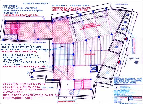
2 Drafting Instruments A Design is as good as its instruments A engineering drawing is a highly stylized graphic representation of an idea. The idea might be of something that we can see such a real or virtual object, space or environment. In some cases, such as an electronic schematic diagram for example, the drawing will bear no visual resemblance to the physical object that will be built from the information it provides.


3 Drafting Instruments A Design is as good as its instruments Conventional CAD
4 Conventional Drafting Tools


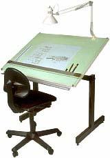
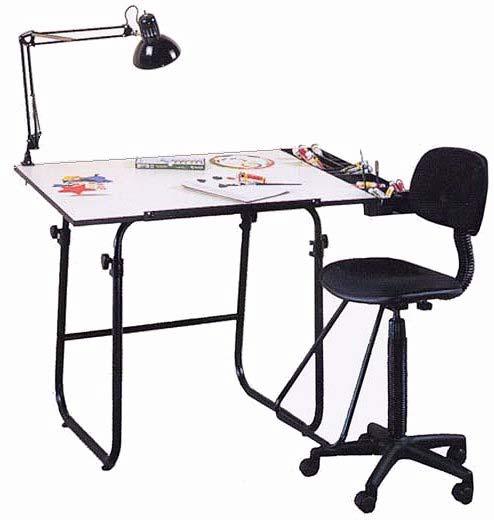
5 Drawing Board Drawing Table Drafting Board

6 Drawing Board Available in a variety of styles and sizes. Most are adjustable up and down, and can tilt to almost any angle from vertical 90 o to horizontal The drawing surface must be clean, flat, smooth, and large enough to accommodate the drawing and some drafting equipment. If a T-square is to be used, at least one edge on the board must be absolutely true. Most quality boards have a metal edge to ensure against warping and to hold the T-square securely Drawing Table with a Drafting machine
7 T-Square It provides a parallel straight edge for the beginning drawing drafter. It is composed of two parts: the head and the blade. The two parts are fastened together at an exact right angle. The blade must be straight and free of any necks and imperfections.

8 T-Square Used to draw horizontal lines on the drawing sheet. Used to draw vertical lines and slanted lines with the help of additional equipment basically 45 o and 60 o triangles. Draw lines only against the upper edge of the blade. Make sure the head is held against the left edge of the drawing board to guarantee parallel lines. Use a T-square to align the drawing paper to the drawing board, and to draw parallel horizontal lines on the paper.
9 Parallel Straight Edge A parallel straightedge is a laminated maple blade with transparent plastic edges similar to those on the T square. Its primary purpose is the same as the T square. The parallel straightedge uses a system of cords and pulleys so that it is supported at both ends by a cord tacked to the drawing board. You can move the straightedge up or down the board with pressure at any point along its length and maintain parallel motion automatically.
10 Parallel Straight Edge The straightedge is locked into place by turning the cord lock clockwise. This permits use of the straightedge on an inclined board. It also prevents accidental movement when you are inking or using mechanical lettering devices. The advantages of the parallel straight- edge become particularly significant when you are working on large drawings. While the T square works well for small work, it becomes unwieldy and inaccurate when you are working on the far right-hand side of large drawings

11 Drafting Machine The standard drafting machine combines the functions of a parallel ruler, protractor, scales, and triangles. Various drafting operations requiring straight and parallel lines may be performed advantageously with a drafting machine. The majority of drafting machines are constructed so that the protractor head may be moved over the surface of a drafting table without change in orientation by means of a parallel- motion linkage.

12 Drafting Machine A drafting machine is a device that attaches to the drafting table and replaces the T-square, triangles and protractors. They increase the accuracy and greatly reduce drafting time. Most drafting machines have a protractor and a vernier which permits reading to 5 minutes of an arc.

13 Drafting Machine

14 A compass is used mainly to draw circles and circular curves of relatively short radius. The large pivot joint compass is satisfactory for drawing circles of 25 mm to about 300 mm in diameter without an extension bar. The pivot joint provides enough friction to hold the legs of the compass in a set position. One of the legs is equipped with a setscrew for mounting either a pen or a pencil attachment on the compass. The metal point extends slightly more than the lead to compensate for the distance the point penetrates the paper. Pivot Compass

15 The other type of compass is the bow compass. Many experienced draftsmen prefer the bow compass over the pivot joint compass. The bow compass is much sturdier and is capable of taking the heavy pressure necessary to produce opaque pencil lines without losing the radius setting. Most compasses have interchangeable needlepoints. The conical or plain needlepoint is used when the compass is used as dividers. Bow Compass


16 Extension bars are available for large bow compasses to draw large diameter circles. Extension Bars
17 Using the compass to draw a circle To draw a circle with the bow compass, the compass is revolved between the thumb and the index finger.

18 Compass Center Disk When many circles are drawn using the same center, the compass needle may tend to bore an oversized hole in the drawing. To prevent these holes, use a device called a horn center or center disk. This disk is placed over the center point. The point of the compass needle is then placed into the hole in its center

19 Divider Dividers are similar to compasses, except that both legs are provided with needle points. As with compasses, dividers are available in large and small sizes, and in pivot joint, and bow types. Pivot joint dividers are used for measurements of approximately 20 mm or more. For measurements of less than 20 mm, bow dividers should be used. Dividers are used to transfer measurements. to step off a series of equal distances, and to divide lines into a number of equal parts A divider is similar to a compass, except that it has a metal point on each leg. It is used to lay off distances and to transfer measurements.

20 Triangles Triangles are used in combination with the T square or straightedge to draw vertical and inclined lines. They are usually made of transparent plastic, which allows you to see your work underneath the triangles. Two standard triangles are used by the drafters. One is the degree triangle. The other is the 45-degree triangle. When laying out lines, triangles are placed firmly against the upper edge of the T-square. Pencils are placed against the left edge of the triangle, and lines drawn upwards, away from the edge. Parallel angular lines are made by moving the triangle to the right after each new line has been drawn.
21 Triangles Triangles are used in combination with the T square or straightedge to draw vertical and inclined lines. They are usually made of transparent plastic, which allows you to see your work underneath the triangles. Two standard triangles are used by the drafters. One is the degree triangle. The other is the 45-degree triangle. When laying out lines, triangles are placed firmly against the upper edge of the T-square. Pencils are placed against the left edge of the triangle, and lines drawn upwards, away from the edge. Parallel angular lines are made by moving the triangle to the right after each new line has been drawn.
22 Triangles To test the straightness of a triangle, place it against the T square and draw a vertical line, then reverse the triangle and draw another line along the same edge. If the triangle is straight, the two lines will coincide; if they don t coincide, the error is half the resulting space

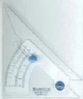
23 Adjustable Triangle The adjustable triangle combines the functions of the triangle and the protractor. When it is used as a right triangle, the hypotenuse can be set and locked at any desired angle to one of the bases. The transparent protractor portion is equivalent to a protractor graduated in 1/2 increments. By holding either base against a T-square, you can measure or draw any angle between 0 and 90. The adjustable triangle allows you to transfer parallel inclined lines by sliding the base along the T square or straightedgean adjustable triangle may take place of both the 30 o - 60 o and 45 o triangles. It is recommended that this tool be used for drawing angular lines that can not be made with the two standard triangles. The adjustable triangle is not as accurate as the solid triangle.


24 Drawing Templates A template is a thin, flat piece of plastic containing various cutout shapes. It is designed to increase the speed and accuracy of the drafter. Templates are available for drawing circles, ellipses, plumbing fixtures, bolts, nuts, screw threads, electronic symbols, springs, gears and much more. A template should be used whenever possible to increase the accuracy and the speed. Circle Template Ellipse Template

25 Drawing Templates Nut, Bolt and Screw Template

26 Drawing Templates Screw Heads Template


27 French Curves and Flex Curves French curves are thin plastic tools that come in assortment of curved surfaces. They are used to produce curved lines that cannot be made by a compass. Most common French curves are actually segments of ellipses, parabolas and hyperbolas. Adjustable curves may also be used to create a smooth curve between a set of points.

28 French Curves and Flex Curves


29 French Curves and Flex Curves Protractors are used for measuring and laying off angles other than those that may be drawn with the triangle or a combination of triangles. Like the triangle, most protractors are made of transparent plastic. They are either circular or semicircular in shape.

30 French Curves and Flex Curves To use a protractor, place the center point on the corner point of the angle. Align the base of the protractor along one side of the angle. The degrees are read along the semicircular edge.

31 Erasing Shield An erasing shield restricts the erasing area so that the correctly drawn lines will not be disturbed during the erasing procedure. It is made from a thin flat piece of metal with variously sized cutouts. The shield is used by placing it over the line to be erased and erasing through the cutout.
32
33

34 Scales in Engineering Drawing On drawing On Site Scale: 1=10 Scale 1:10
35 Metric Scales

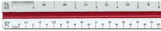
36 Inches Scales

37 Wooden Pencils Grades Softest Hardest
38 Pencil Grades Softest Hardest
39 Pen Sizes and Line Weights Line weights are a vital part of conventional technical graphics language. They are embodied to the extent of being defined in national and international standards. In manual drafting, different pen sizes allow the drafter to give different line weights to the lines in the drawing. Line types and line weights allow drawings to communicate information that would otherwise be very difficult to convey. For example: Hidden outlines Paths of motion Planes of symmetry Fictitious outlines such as major and minor diameters of screw threads Dimensions and projections Materials (hatching) Centers and imaginary intersections
40 Pen Sizes Conventional practice is that only two different line weights be used on any one drawing. This is subject to discretion and some disciplines regularly use three, and occasionally four. Different line weights. Consistency and clarity of communication are the deciding factors. You could use 10 line weights in a drawing provided everyone understood what they all meant and the document was consistent
41 . Pen Sizes Line weight groups chosen for most engineering drawings are selected from adjacent pen thicknesses (in mm). The table below indicates line weight groups for various sheet sizes. Pen thickness are shown in mm A4, A2, A A A
42 . Line Types Line type Thickness Example Application Fine Thick Continuous thick Visible outlines, existing features, cut edges, general line work Continuous medium Used where another level of line weight would assist the delineation e.g. internal line work, notes Continuous thin Fictitious outlines, imaginary intersections and projections, hatching, dimensions, break lines Dashed thick Hidden outlines and edges Dashed thin Chain thick Indication of special surface requirements or (sometimes with a text component) to indicate pipelines and services Chain thin Center lines, motion paths, indication of repeated detail

43 . LINE STANDARDS NAME CONVENTION DESCRIPTION AND APPLICATION SAMPLE CENTER LINES THIN LINES MADE UP OF LONG AND SHORT DASHES ALTERNATELY SPACED AND CONSISTENT IN LENGTH USED TO INDICATE SYMMETRU ABOUT AN AXIS AND LOCATION OF CENTERS VISIBLE LINES HEAVY UNBROKEN LINES USED TO INDICATE VISIBLE EDGES OF AN OBJECT HIDDEN LINES MEDIUM LINES WITH SHORT EVENLY SPACED DASHES USED TO INDICATE CONCEALED EDGES THIN UNBROKEN LINES EXTENSION LINES USED TO INDICATE EXTENT OF DIMENSIONS DIMENSION LINES THIN LINES TERMINATED WITH ARROWS HEADS AT EACH END USED TO INDICATE DISTANCE MEASURED

44 Scales Drawing Table Adjustable Triangle
Chapter 2 Using Drawing Tools & Applied Geometry
 Chapter 2 Using Drawing Tools & Applied Geometry TOPICS Preparation of Tools. Using of Tools Applied Geometry PREPARATION OF TOOLS Fastening Paper to Drafting Board 1. Place the paper close to the table
AutoCAD 2D-I. Module 1: Introduction to Drawing Tools. IAT Curriculum Unit PREPARED BY. January 2011
 AutoCAD 2D-I Module 1: Introduction to Drawing Tools PREPARED BY IAT Curriculum Unit January 2011 Institute of Applied Technology, 2011 Module 1: Introduction to Drawing Tools Module Objectives After
DRAWING INSTRUMENTS AND THEIR USES
 Chapter - 1A DRAWING INSTRUMENTS AND THEIR USES Drawing Instruments are used to prepare neat and accurate Drawings. To a greater extent, the accuracy of the Drawings depend on the quality of instruments
Chapter 1 Overview of an Engineering Drawing
 Chapter 1 Overview of an Engineering Drawing TOPICS Graphics language Engineering drawing Projection methods Orthographic projection Drawing standards TOPICS Traditional Drawing Tools Lettering Freehand
(As per New Revised Syllabus of Anna University) Department of Mechanical Engineering. SATHYABAMA UNIVERSITY Jeppiaar Nagar, Chennai
 Department of Mechanical Engineering. SATHYABAMA UNIVERSITY Jeppiaar Nagar, Chennai") (1*,1((5,1* *5$3+,&6 (As per New Revised Syllabus of Anna University) Dr. S.RAMACHANDRAN, M.E., Ph.D. Professor & Head K. PANDIAN, M.E., E.V.V.RAMANAMURTHY, M.Tech., R. DEVARAJ, M.E., Associate Professors
(1*,1((5,1* *5$3+,&6 (As per New Revised Syllabus of Anna University) Dr. S.RAMACHANDRAN, M.E., Ph.D. Professor & Head K. PANDIAN, M.E., E.V.V.RAMANAMURTHY, M.Tech., R. DEVARAJ, M.E., Associate Professors
Drafting Dictionary (Mechanical Board Drafting)
") Description In this lesson the teacher will introduce the tools and equipment specific to board drafting. Board drafting (also known as manual drafting) refers to precision drawing with specialized instruments.
Description In this lesson the teacher will introduce the tools and equipment specific to board drafting. Board drafting (also known as manual drafting) refers to precision drawing with specialized instruments.
Introduction CHAPTER Graphics: A Tool to Communicate Ideas
 CHAPTER 1 Introduction 1.1 Graphics: A Tool to Communicate Ideas Engineering graphics or drawing is the universal language of engineers. An engineer communicate his idea to others with the help of this
Copyrighted Material. Copyrighted Material. Copyrighted. Copyrighted. Material
 Engineering Graphics ORTHOGRAPHIC PROJECTION People who work with drawings develop the ability to look at lines on paper or on a computer screen and "see" the shapes of the objects the lines represent.
Vocabulary. Cavalier oblique: An oblique drawing in which the depth axis lines are drawn at full scale (full size).
.") 10-11-11 Vocabulary Cavalier oblique: An oblique drawing in which the depth axis lines are drawn at full scale (full size). 10-12-11 Vocabulary Centerlines: Thin lines made up of long and short dashes
10-11-11 Vocabulary Cavalier oblique: An oblique drawing in which the depth axis lines are drawn at full scale (full size). 10-12-11 Vocabulary Centerlines: Thin lines made up of long and short dashes
MISS. HANNA S CLASSROOM RULES
 MISS. HANNA S CLASSROOM RULES 1. My students never fail. I believe in you and so shall you! Miss. Hanna s Quote! 2. Come to class on time. 3. Bring a positive attitude. 4. Come prepared and bring your
Student Name: Teacher: Date: District: Rowan. Assessment: 9_12 T and I IC61 - Drafting I Test 1. Description: Unit C - Sketching - Test 2.
 Student Name: Teacher: Date: District: Rowan Assessment: 9_12 T and I IC61 - Drafting I Test 1 Description: Unit C - Sketching - Test 2 Form: 501 1. The most often used combination of views includes the:
Continuous thick. Continuous thin. Continuous thin straight with zigzags. Dashed thin line. Chain thin. Chain thin double dash
 Types of line used Continuous thick Used for visible outlines and edges. Continuous thin Used for projection, dimensioning, leader lines, hatching and short centre lines. Continuous thin straight with
Sketching Fundamentals
 Sketching Fundamentals Learning Outcome When you complete this module you will be able to: Make basic engineering sketches of plant equipment. Learning Objectives Here is what you will be able to do when
Chapter 13 SQUARES HOW TO CHOOSE AND USE THEM TM The Types and Uses section provides you with a list of
 Chapter 13 SQUARES HOW TO CHOOSE AND USE THEM The Types and Uses section provides you with a list of the types of squares. These pages should help you select the right square for the job. The Using Squares
Unit 4: Geometric Construction (Chapter4: Geometry For Modeling and Design)
") Unit 4: Geometric Construction (Chapter4: Geometry For Modeling and Design) DFTG-1305 Technical Drafting Instructor: Jimmy Nhan OBJECTIVES 1. Identify and specify basic geometric elements and primitive
Unit 4: Geometric Construction (Chapter4: Geometry For Modeling and Design) DFTG-1305 Technical Drafting Instructor: Jimmy Nhan OBJECTIVES 1. Identify and specify basic geometric elements and primitive
ORTHOGRAPHIC PROJECTIONS. Ms. Sicola
 ORTHOGRAPHIC PROJECTIONS Ms. Sicola Objectives List the six principal views of projection Sketch the top, front and right-side views of an object with normal, inclined, and oblique surfaces Objectives
Multi-View Drawing Review
 Multi-View Drawing Review Sacramento City College EDT 300/ENGR 306 EDT 300 / ENGR 306 - Chapter 5 1 Objectives Identify and select the various views of an object. Determine the number of views needed to
2004 Academic Challenge
 2004 Academic Challenge ENGINEERING GRAPHICS TEST - REGIONAL Engineering Graphics Test Production Team Ryan Brown, Illinois State University Author/Team Coordinator Kevin Devine, Illinois State University
Guide To British Standards
 Guide To British Standards Higher Graphic Communication C O N T E N T S page TITLE BLOCK 2 DRAWING SCALES 2 LINE TYPES 3 ORTHOGRAPHIC PROJECTION 4 SECTIONAL VIEWS 4 SCREW THREADS & COMPONENTS 7 INTERUPTTED
The type of drafting we will be studying is called mechanical drafting. It is the typical foundation of all drafting fields.
 Design Drafting Lectures Lecture 1 Introduction: Tools and Trades Drafter Defined: Drafters translate ideas and sketches of engineers, architects, and scientists into detailed drawings which are used in
2003 Academic Challenge
 Worldwide Youth in Science and Engineering 2003 Academic Challenge ENGINEERING GRAPHICS TEST - SECTIONAL Engineering Graphics Test Production Team Ryan Brown, Illinois State University Author/Team Coordinator
2010 Academic Challenge
 2010 Academic Challenge ENGINEERING GRAPHICS TEST STATE FINALS This Test Consists of 40 Questions Engineering Graphics Test Production Team Ryan K. Brown, Illinois State University Author/Team Leader Jacob
MODELING AND DESIGN C H A P T E R F O U R
 MODELING AND DESIGN C H A P T E R F O U R OBJECTIVES 1. Identify and specify basic geometric elements and primitive shapes. 2. Select a 2D profile that best describes the shape of an object. 3. Identify
ENGINEERING GRAPHICS ESSENTIALS
 ENGINEERING GRAPHICS ESSENTIALS Text and Digital Learning KIRSTIE PLANTENBERG FIFTH EDITION SDC P U B L I C AT I O N S Better Textbooks. Lower Prices. www.sdcpublications.com ACCESS CODE UNIQUE CODE INSIDE
Orthographic Projection
 Orthographic Projection Why Orthographic Projection is used in technical drawing Orthographic projection is a method of producing a number of separate two-dimensional inter-related views, which are mutually
2003 Academic Challenge
 Worldwide Youth in Science and Engineering 2003 Academic Challenge ENGINEERING GRAPHICS TEST - REGIONAL Engineering Graphics Test Production Team Ryan Brown, Illinois State University Author/Team Coordinator
2012 Academic Challenge
 2012 Academic Challenge ENGINEERING GRAPHICS TEST STATE FINAL This Test Consists of 40 Questions Engineering Graphics Test Production Team Ryan Brown, Illinois State University Author/Team Leader Jacob
Multiview Drawing. Definition: Graphical representation of a 3- dimensional object on one plane (sheet of paper) using two or more views.
 using two or more views.") Multiview Drawing Definition: Graphical representation of a 3- dimensional object on one plane (sheet of paper) using two or more views. Multiview Drawing Another name for multiview drawing is orthographic
Multiview Drawing Definition: Graphical representation of a 3- dimensional object on one plane (sheet of paper) using two or more views. Multiview Drawing Another name for multiview drawing is orthographic
Two-Dimensional Drawing
 22 Chapter Cxxxx 40757 3/19/08 10:24 AM Page 1 7% 3% 3% 18% 20% 22 Chapter CXXXX 40757 Page 1 03/18/08 MD 22 Two-Dimensional Drawing objectives After completing this chapter, you should be able to Identify
Sketch-Up Guide for Woodworkers
 W Enjoy this selection from Sketch-Up Guide for Woodworkers In just seconds, you can enjoy this ebook of Sketch-Up Guide for Woodworkers. SketchUp Guide for BUY NOW! Google See how our magazine makes you
Engineering Graphics- Basics.
 Engineering Graphics- Basics DRAWINGS: ( A Graphical Representation) The Fact about: If compared with Verbal or Written Description, Drawings offer far better idea about the Shape, Size & Appearance of
Chapter 2: Dimensioning Basic Topics Advanced Topics Exercises
 Chapter 2: Dimensioning Basic Topics Advanced Topics Exercises Dimensioning: Basic Topics Summary 2-1) Detailed Drawings 2-2) Learning to Dimension 2-3) Dimension Appearance and Techniques. 2-4) Dimensioning
Contents. Notes on the use of this publication
 Contents Preface xxiii Scope Notes on the use of this publication xxv xxvi 1 Layout of drawings 1 1.1 General 1 1.2 Drawing sheets 1 1.3 Title block 2 1.4 Borders and frames 2 1.5 Drawing formats 2 1.6
UNIT I PLANE CURVES AND FREE HAND SKETCHING CONIC SECTIONS
 UNIT I PLANE CURVES AND FREE HAND SKETCHING CONIC SECTIONS Definition: The sections obtained by the intersection of a right circular cone by a cutting plane in different positions are called conic sections
GENERAL NOTES: Page 1 of 9
 Laminating A Zia Into A Turning Blank by W. H. Kloepping, Jan. 2009 This describes how a zia (the New Mexico state symbol) can be laminated into a turning blank. Materials needed: Square Turning Block
Engineering Graphics Essentials with AutoCAD 2015 Instruction
 Kirstie Plantenberg Engineering Graphics Essentials with AutoCAD 2015 Instruction Text and Video Instruction Multimedia Disc SDC P U B L I C AT I O N S Better Textbooks. Lower Prices. www.sdcpublications.com
Beginning Engineering Graphics 3 rd Week Lecture Notes Instructor: Edward N. Locke Topic: The Coordinate System, Types of Drawings and Orthographic
 Beginning Engineering Graphics 3 rd Week Lecture Notes Instructor: Edward N. Locke Topic: The Coordinate System, Types of Drawings and Orthographic 1 st Subject: The Cartesian Coordinate System The Cartesian
11/12/2015 CHAPTER 7. Axonometric Drawings (cont.) Axonometric Drawings (cont.) Isometric Projections (cont.) 1) Axonometric Drawings
 Axonometric Drawings (cont.) Isometric Projections (cont.) 1) Axonometric Drawings") CHAPTER 7 1) Axonometric Drawings 1) Introduction Isometric & Oblique Projection Axonometric projection is a parallel projection technique used to create a pictorial drawing of an object by rotating the
CHAPTER 7 1) Axonometric Drawings 1) Introduction Isometric & Oblique Projection Axonometric projection is a parallel projection technique used to create a pictorial drawing of an object by rotating the
ENGINEERING GRAPHICS ESSENTIALS
 ENGINEERING GRAPHICS ESSENTIALS with AutoCAD 2012 Instruction Introduction to AutoCAD Engineering Graphics Principles Hand Sketching Text and Independent Learning CD Independent Learning CD: A Comprehensive
CHAPTER 01 PRESENTATION OF TECHNICAL DRAWING. Prepared by: Sio Sreymean
 CHAPTER 01 PRESENTATION OF TECHNICAL DRAWING Prepared by: Sio Sreymean 2015-2016 Why do we need to study this subject? Effectiveness of Graphics Language 1. Try to write a description of this object. 2.
Technological Design Mr. Wadowski. Orthographic & Isometric Drawing Lesson
 Technological Design Mr. Wadowski Orthographic & Isometric Drawing Lesson TOPICS Working Drawings, Isometric Drawings & Orthographic Drawings Glass box concept Multiview projection Orthographic projection
Civil Engineering Drawing
 Civil Engineering Drawing Third Angle Projection In third angle projection, front view is always drawn at the bottom, top view just above the front view, and end view, is drawn on that side of the front
Orthographic Drawing (Architectural Board Drafting)
") Design and Drafting Description In this activity, the teacher will introduce orthographic projection, in which a multi-view drawing shows how the sides of an object are related to each another. Students
Design and Drafting Description In this activity, the teacher will introduce orthographic projection, in which a multi-view drawing shows how the sides of an object are related to each another. Students
Engineering Graphics, Class 8 Orthographic Projection. Mohammad I. Kilani. Mechanical Engineering Department University of Jordan
 Engineering Graphics, Class 8 Orthographic Projection Mohammad I. Kilani Mechanical Engineering Department University of Jordan Multi view drawings Multi view drawings provide accurate shape descriptions
Graphic representation in technological projects
 1st ESO: Technology, Programming and Robotics Graphic representation in technological projects Author: Guillermo Gómez Revision: Pablo Rivas Martín Contents 1 Prior knowledge... 2 2 Keywords... 2 3 Mindmap
Engineering Working Drawings Basics
 Engineering Working Drawings Basics Engineering graphics is an effective way of communicating technical ideas and it is an essential tool in engineering design where most of the design process is graphically
DFTG-1305 Technical Drafting Prof. Francis Ha
 DFTG-1305 Technical Drafting Prof. Francis Ha Session 4 Orthographic Projection (or Multiview Projection) Reading: Geisecke s textbook: 14 th Ed. Chapter 5 p.162 15 th Ed. Chapter 6 p.232 Update: 18-0205
CE 100 Civil Engineering Drawing Sessional (Lab Manual)
") CE 100 Civil Engineering Drawing Sessional (Lab Manual) Department of Civil Engineering Ahsanullah University of Science and Technology November, 2017 1 Preface This course is designed to provide civil
CE 100 Civil Engineering Drawing Sessional (Lab Manual) Department of Civil Engineering Ahsanullah University of Science and Technology November, 2017 1 Preface This course is designed to provide civil
CLASS views from detail on a grid paper. (use appropriate line types to show features) - Optional views. Turn in for grading on class 6 (06/04)
 - Optional views. Turn in for grading on class 6 (06/04)") CLASS 4 Review: - Projections - Orthographic projections Lab: - 3 views from detail on a grid paper. (use appropriate line types to show features) - Optional views. Turn in for grading on class 6 (06/04)
CLASS 4 Review: - Projections - Orthographic projections Lab: - 3 views from detail on a grid paper. (use appropriate line types to show features) - Optional views. Turn in for grading on class 6 (06/04)
Engineering Graphics, Class 5 Geometric Construction. Mohammad I. Kilani. Mechanical Engineering Department University of Jordan
 Engineering Graphics, Class 5 Geometric Construction Mohammad I. Kilani Mechanical Engineering Department University of Jordan Conic Sections A cone is generated by a straight line moving in contact with
ENGINEERING GRAPHICS
 ENGINEERING GRAPHICS Time allowed : 3 hours Maximum Marks : 70 Note : (ii) Attempt all the questions. Use both sides of the drawing sheet, if necessary. (iii) All dimensions are in millimetres. (iv) Missing
AABTKJX by Prentice Hall, Inc. A Pearson Company
 Figure Number: 03-01 Page Number: Principal Items of Equipment. AABTKJX0 Figure Number: 03-02 Page Number: The T-square. AABTKJY0 Figure Number: 03-03 Page Number: Testing the Working Edge of the Drawing
ORTHOGRAPHIC PROJECTION
 ORTHOGRAPHIC PROJECTION C H A P T E R S I X OBJECTIVES 1. Recognize and the symbol for third-angle projection. 2. List the six principal views of projection. 3. Understand which views show depth in a drawing
Multiview Projection
 DFTG-1305 Technical Drafting Prof. Francis Ha Session 4 Multiview Projection (or Orthographic Projection) Reading: Geisecke s textbook: 14 th Ed. Chapter 5 p.162 15 th Ed. Chapter 6 p.232 Update: 17-0510
Drawing Types & Construction Drawings
 Drawing Types & Construction Drawings Building projects require several types of specialised drawings. This collection of drawings, known as a project set, includes: Location Plan Site Plan Floor Plan
2007 Academic Challenge
 2007 Academic Challenge ENGINEERING GRAPHICS TEST - STATE FINALS This Test Consists of 50 Questions Engineering Graphics Test Production Team Ryan Brown, Illinois State University Author/Team Coordinator
Index Set Squares Measurement / Drawing Instruments Curves Scale Ruler T-Squares
 Index Set Squares Measurement / Drawing Instruments Curves Scale Ruler T-Squares Mechanical Pencil Lead and Pencil Ink PVC Free Eraser Eraser Pen Eraser Shield Black / White Board Instruments Masking Tape
A Concise Introduction to Engineering Graphics
 A Concise Introduction to Engineering Graphics Fourth Edition Including Worksheet Series A Timothy J. Sexton, Professor Department of Industrial Technology Ohio University BONUS Book on CD: TECHNICAL GRAPHICS
Machine Drawing MEC-304. Dr. Shankar Sehgal Asst. Professor in Mech. Engg. UIET, Panjab University, Chandigarh
 Machine Drawing MEC-304 Dr. Shankar Sehgal Asst. Professor in Mech. Engg. UIET, Panjab University, Chandigarh Standard Abbreviations Standard Abbreviations Standard Abbreviations Standard Abbreviations
Chapter 1 Overview of a Technical Drawing
 Chapter 1 Overview of a Technical Drawing TOPICS Graphics language Engineering drawing Projection methods Orthographic projection Drawing standards TOPICS Traditional Drawing Tools Lettering Dimensioning
1 st Subject: 2D Geometric Shape Construction and Division
 Joint Beginning and Intermediate Engineering Graphics 2 nd Week 1st Meeting Lecture Notes Instructor: Edward N. Locke Topic: Geometric Construction 1 st Subject: 2D Geometric Shape Construction and Division
Multiviews and Auxiliary Views
 Multiviews and Auxiliary Views Multiviews and Auxiliary Views Objectives Explain orthographic and multiview projection. Identifying the six principal views. Apply standard line practices to multiviews
ENGINEERING DRAWING INTRODUCTION
 ENGINEERING DRAWING INTRODUCTION Drawing is the graphical language of engineers which is built upon certain basic principles and standards. A good drawing can be prepared making use of these principles
ENGINEERING GRAPHICS 1.0 Introduction Engineering Graphics Drawing as an art Artist Graphic design Engineering graphics engineering drawing
 ENGINEERING GRAPHICS 1.0 Introduction Engineering is the profession in which the knowledge of mathematics and science gained by study, experience and practice is applied with good judgment to develop a
Question 1. Flat file. Half -round. Round file. Three square ( triangle ) Needle files. Page 1 of 46
 Needle files. Page 1 of 46") Question 1 Name Picture Cross section Uses: Cut pattern:: Flat file Half -round Round file Three square ( triangle ) Needle files Page 1 of 46 Question 2 The graph shown below is the data collected for
Question 1 Name Picture Cross section Uses: Cut pattern:: Flat file Half -round Round file Three square ( triangle ) Needle files Page 1 of 46 Question 2 The graph shown below is the data collected for
Dimensioning. Dimensions: Are required on detail drawings. Provide the shape, size and location description: ASME Dimensioning Standards
 Dimensioning Dimensions: Are required on detail drawings. Provide the shape, size and location description: - Size dimensions - Location dimensions - Notes Local notes (specific notes) General notes ASME
GOAL Practise techniques for creating various types of geometric lines by constructing and reproducing figures. sheet of letter-sized white paper
 TECHNIQUE STUDENT BOOK Chapter 11, page 340 TOOLBOX Pages 62 67 GOAL Practise techniques for creating various types of geometric lines by constructing and reproducing figures. MATERIALS drawing board T-square
Study Unit. Auxiliary Views. This sneak preview of your study material has been prepared in advance of the book's actual online release.
 Study Unit Auxiliary Views This sneak preview of your study material has been prepared in advance of the book's actual online release. iii Preview You re entering now into another subject area in your
Chapter 1 Introduction
 Chapter 1 Introduction Contents Engineering drawing Drawing standards Drawing sheet Scale Lettering Line types Engineering Drawing Contents Engineering Drawing Effectiveness of Graphic Language 1. Try
Scale and Dimensioning (Architectural Board Drafting)
") Youth Explore Trades Skills Description In this activity, the teacher will first select an object that is larger than the page and scale it to fit in the designated drawing area to explain architectural
Youth Explore Trades Skills Description In this activity, the teacher will first select an object that is larger than the page and scale it to fit in the designated drawing area to explain architectural
Finish Neck and Fretboard Wednesday, January 16, :36 PM
 ASL Breakdown Page 1 Finish Neck and Fretboard Wednesday, January 16, 2013 9:36 PM Layer on the fret board, making sure registration pins are in place and everything lays flat. The 3/16" aluminum nutsurrogate
DFTG-1305 Technical Drafting Prof. Francis Ha
 DFTG-1305 Technical Drafting Prof. Francis Ha Session 5 Dimensioning Geisecke s textbook: 14 th Ed. Chapter 10 p. 362 15 th Ed. Chapter 11 p. 502 Update: 17-0508 Dimensioning Part 1 of 2 Dimensioning Summary
Test Answers and Exam Booklet. Geometric Tolerancing
 Test Answers and Exam Booklet Geometric Tolerancing iii Contents ANSWERS TO THE GEOMETRIC TOLERANCING TEST............. 1 Part 1. Questions Part 2. Calculations SAMPLE ANSWERS TO THE GEOMETRIC TOLERANCING
Planning and Designing Projects
 Lesson A3 1 Planning and Designing Projects Unit A. Mechanical Systems and Technology Problem Area 3. Construction Systems Lesson 1. Planning and Designing Projects Content/Process Statement: ACS10 Core
ENGINEERING GRAPHICS
 ENGINEERING GRAPHICS CLASS - XII (046) DESIGN OF THE QUESTION PAPER Time : 3 Hrs Max. Marks : 70 The weightage of the distribution of marks over different contents of the question paper shall be as follows:
Geometric Dimensioning and Tolerancing
 Geometric Dimensioning and Tolerancing (Known as GDT) What is GDT Helps ensure interchangeability of parts. Use is dictated by function and relationship of the part feature. It does not take the place
Using Siemens NX 11 Software. Sheet Metal Design - Casing
 Using Siemens NX 11 Software Sheet Metal Design - Casing Based on a YouTube NX tutorial 1. 1 https://www.youtube.com/watch?v=-siyi1vz87k A&M CAD in mechanical engineering 1 1 Introduction. Start NX 11
3. The dimensioning SYMBOLS for arcs and circles should be given:
 Draft Student Name: Teacher: District: Date: Wake County Test: 9_12 T and I IC61 - Drafting I Test 2 Description: 4.08 Dimensioning Form: 501 1. The MINIMUM amount of space between two, ADJACENT DIMENSION
UNIT Lines and Symbols
 3 UNIT Lines and Symbols Various lines on a drawing have different meanings. They may appear solid, broken, thick, or thin. Each is designed to help the blueprint reader make an interpretation. The standards
Flat file. Round file. Hand file. Half -round. Mill file. Square file
 Name Picture Cross section Uses: Cut pattern:: Hand file used for roughing and finishing. It has double cut teeth on two faces, single cut teeth on one edge, and one safe edge Flat file used for roughing
UNIT 5a STANDARD ORTHOGRAPHIC VIEW DRAWINGS
 UNIT 5a STANDARD ORTHOGRAPHIC VIEW DRAWINGS 5.1 Introduction Orthographic views are 2D images of a 3D object obtained by viewing it from different orthogonal directions. Six principal views are possible
HEAVY DUTY GASKET CUTTER
 HEAVY DUTY GASKET CUTTER GUIDE TO PERFECT GASKETS CUTTING GASKETS 1 TO 13 IN DIAMETER: 1. Lay out gasket outer diameter (OD), inner diameter (ID) and bolt holes on template or gasket material. See section
ENGINEERING GRAPHICS ESSENTIALS. (A Text and Lecture Aid) Second Edition. Kirstie Plantenberg University of Detroit Mercy SDC PUBLICATIONS
 Second Edition. Kirstie Plantenberg University of Detroit Mercy SDC PUBLICATIONS") ENGINEERING GRAPHICS ESSENTIALS (A Text and Lecture Aid) Second Edition Kirstie Plantenberg University of Detroit Mercy SDC PUBLICATIONS Schroff Development Corporation www.schroff.com www.schroff-europe.com
ENGINEERING GRAPHICS ESSENTIALS (A Text and Lecture Aid) Second Edition Kirstie Plantenberg University of Detroit Mercy SDC PUBLICATIONS Schroff Development Corporation www.schroff.com www.schroff-europe.com
Engineering Graphics & Technology. NQF Level 2. Sparrow Consulting LECTURER S GUIDE TVET FIRST
 Engineering Graphics & Technology NQF Level 2 Sparrow Consulting LECTURER S GUIDE TVET FIRST Engineering Graphics & Technology NQF Level 2 Lecturer s Guide M Conradie Engineering Graphics & Technology
ISOMETRIC PROJECTION. Contents. Isometric Scale. Construction of Isometric Scale. Methods to draw isometric projections/isometric views
 ISOMETRIC PROJECTION Contents Introduction Principle of Isometric Projection Isometric Scale Construction of Isometric Scale Isometric View (Isometric Drawings) Methods to draw isometric projections/isometric
2009 Academic Challenge
 2009 Academic Challenge ENGINEERING GRAPHICS TEST STATE FINALS This Test Consists of 50 Questions Engineering Graphics Test Production Team Ryan Brown, Illinois State University Author/Team Leader Kevin
Surface Developments. Sacramento City College Engineering Design Technology. Surface Developments 1
 Surface Developments Sacramento City College Engineering Design Technology Surface Developments 1 Surface Developments A surface development is a full-size layout of an object made on a single flat plane.
Alphabet of Lines Chapter 3
 Alphabet of Lines Chapter 3 Sacramento City College EDT 300/ ENGR 306 EDT 300/306 - Basic Technical Drafting 1 Alphabet of Lines The design industry has agreed on a set of standard lines that are used
359 Precision Universal Bevel Vernier Protractors - Graduations in Degrees through 360º In Case
 359 PRECISION UNIVERSAL BEVEL VERNIER WITH FINE ADJUSTMENT GRADUATIONS IN DEGREES THRU 360º These tools are designed for precision measuring and for laying out angles. The protractor is one of the most
Isometric Drawing (Architectural Board drafting)
") Design and Drafting Description Isometric drawings use perspective to communicate a large amount of information in a single drawing. Isometric drawings show three sides of an object, making it easier to
Design and Drafting Description Isometric drawings use perspective to communicate a large amount of information in a single drawing. Isometric drawings show three sides of an object, making it easier to
ENGINEERING DRAWING. 1. Set squares are used to draw different angles. What is the angel a formed by the 45⁰ set square? Give a brief answer.
 ENGINEERING DRAWING 1. Set squares are used to draw different angles. What is the angel a formed by the 45⁰ set square? Give a brief answer. 2. Which is the correct method of hatching a plane surface?
Layout Tools. Marking and Layout Tools
 Best Welds, Contour Sales Vendor Code: BWS, CON Welders & Pipe Fitters Rap-Around Double ruled so both the top and bottom surfaces can be used for layouts - it is never upside-down! Packaged in its own
SDC PUBLICATIONS. Schroff Development Corporation
 SDC PUBLICATIONS Schroff Development Corporation www.schroff.com www.schroff-europe.com SECTIONING In chapter 3 you will learn how to create various types of sectional views. Sectional views allow you
Student Name: Teacher: Date: District: Rowan. Assessment: 9_12 T and I IC61 - Drafting I Test 2. Description: Drafting 1 - Test 6.
 Student Name: Teacher: Date: District: Rowan Assessment: 9_12 T and I IC61 - Drafting I Test 2 Description: Drafting 1 - Test 6 Form: 501 1. 2X on a hole note means: A. Double the size of the hole. B.
Set No - 1 I B. Tech I Semester Regular/Supplementary Examinations Jan./Feb ENGINEERING DRAWING (EEE)
") Set No - 1 I B. Tech I Semester Regular/Supplementary Examinations Jan./Feb. - 2015 ENGINEERING DRAWING Time: 3 hours (EEE) Question Paper Consists of Part-A and Part-B Answering the question in Part-A
Set No - 1 I B. Tech I Semester Regular/Supplementary Examinations Jan./Feb. - 2015 ENGINEERING DRAWING Time: 3 hours (EEE) Question Paper Consists of Part-A and Part-B Answering the question in Part-A
1 st Subject: Types and Conventions of Dimensions and Notes
 Beginning Engineering Graphics 7 th Week Lecture Notes Instructor: Edward N. Locke Topic: Dimensions, Tolerances, Graphs and Charts 1 st Subject: Types and Conventions of Dimensions and Notes A. Definitions
Brief Introduction to Engineering Graphics The use of drawings to convey information. Sketching freehand straight edge
 Brief Introduction to Engineering Graphics The use of drawings to convey information. Sketching freehand straight edge CAD drawings 2D drafting 3D model to 2D drawings 1 Different Graphical Representation
The Magic Circle Basic Lesson. Developed by The Alexandria Seaport Foundation
 The Magic Circle Basic Lesson Developed by The Alexandria Seaport Foundation The Tools Needed Compass Straightedge Pencil Paper (not graph paper, 8.5 x 11 is fine) Your Brain (the most important tool!)
Simple Geometry For Saddlemakers
 Simple Geometry For Saddlemakers Written and illustrated By Verlane Desgrange 2003 Most saddlemakers fear the word geometry as they believe it is complicated and not useful for their purposes. This is
GlideRite Retractable Cover System For HotSpring & Tiger River Spas (except Classic & pre-2000 Landmark Spas)
") List of Contents Quantity Description 12 #10 x 1 ½ Flat Head Phillips Screw (see pg. 2) 2 #10 x ½ Pan Head Phillips Screw (see pg. 2) 8 ¼ x 2 ½ Lag Bolt (see pg. 2) 7 ¼ 20 x 5 / 8 Hex Head Bolt (see pg.
List of Contents Quantity Description 12 #10 x 1 ½ Flat Head Phillips Screw (see pg. 2) 2 #10 x ½ Pan Head Phillips Screw (see pg. 2) 8 ¼ x 2 ½ Lag Bolt (see pg. 2) 7 ¼ 20 x 5 / 8 Hex Head Bolt (see pg.