Lecture #4 MULTIVIEW PROJECTION RES 112E COMPUTER AIDED TECHNICAL DRAWING ITU
|
|
|
- Ralph Randall
- 5 years ago
- Views:
Transcription

1 Lecture #4 MULTIVIEW PROJECTION
2 This week You will learn multi-view projection. The steps to follow are: Projections (ISO-E & ISO-A) Multi-view drawings Views (Basic,Auxiliary, Detailed etc.) Sketching 2-D Geometry Assignment # 3
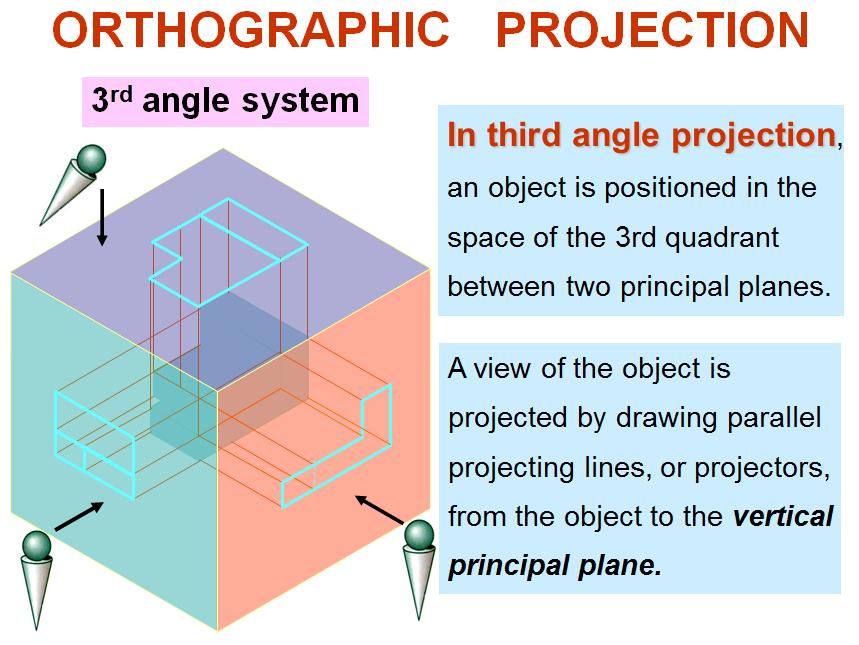
3 Principles ORTHOGRAPHIC PROJECTION
4
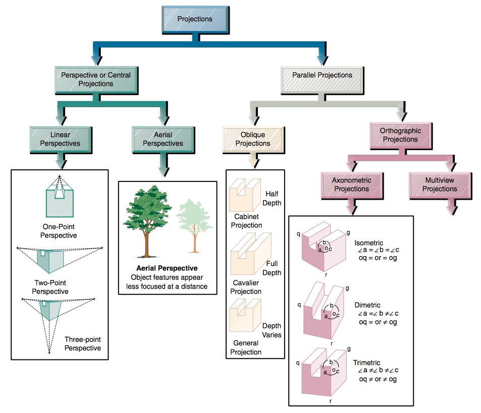
5 Projections Multi-view projection (Orthographic projections): are drawn as multi view drawings, which show flat representations of principal views of the object. Parallel Projection is a type of projection where the line of sight or projectors are parallel and are perpendicular to the picture planes. Oblique Projections: actually show the full size of one view. Axonometric Projections: are three-dimensional drawings, and are of three different varieties: Isometric, Dimetric and Trimetric. Perspective projections are drawings which attempt to replicate what the human eye actually sees when it views an object.

6 The attributes of projection methods

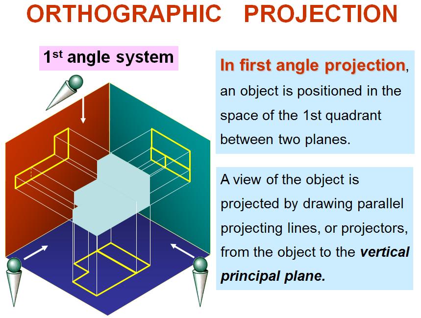
7 What is orthographic? Orthographic projection is a method of producing a number of separate two-dimensional inter-related views, which are mutually at right angles to each other. Using this projection, even the most complex shape can be fully described. the plane upon which the frontal view is projected the plane upon which the top view is projected the plane upon which the side view is projected

8 History of orthographic The way of communicating ideas that everybody understood was a problem that faced Gaspard Monge (as an Engineer in the French Military). He devised a system that could be used to communicate an object to anyone across the world. This system is called Orthographic Projection and was quickly adopted by army engineers.

9 Orthographic Projections Orthographic projections are drawings where the projectors, the observer or station point remain parallel to each other and perpendicular to the plane of projection. Orthographic projections are further subdivided into axonomet ric projections and multi-view projections. Effective in technical representation of objects.
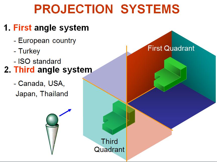
10 Projection systems
11 Orthographic projection
12 Orthographic projection
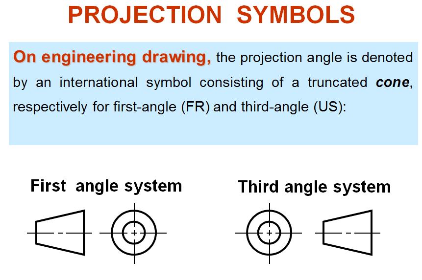
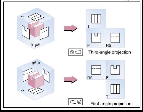
13 Projection Symbols
14

15 Miter line Orthographic Projection utilizes a Miter Line drawn at 45 degrees which enables information to be projected from the top view to the side view, and from the side view to the top view.
16 Principles MUTLIVIEW DRAWING
17 What is multiview? Another name for orthographic projection is multiview drawing. Multi-view (multiplanar) projection is a method by which the exact shape of an object can be represented by two or more separate views produced on projection planes that are at right angles to each other. Involves visualization and implementation oability to see an object clearly in the mind s eye. oprocess (steps) of drawing the object
18 Multiview drawing omultiview drawing is classified as a parallel projection technique, because the lines of sight used to view the object are parallel oa system that allows you to make a two-dimensional drawingof a three-dimensional object. othe images are called views. TOP BACK L.SIDE FRONT R.SIDE BOTTOM

19 Basic views There are 9 different types of views used for engineering drawings, namely Front view Top view Bottom view Rear view Left-side view Right-side view Auxiliary view Section view Detailed view
20


21 Alphabet of Lines
22 Linetypes Center Lines You will draw the centerlines for the circle. Center lines for holes must be included in all views. A centermark and four lines extending beyond the four quadrant points are used. The centerline is used to: o Show the axis of symmetry of a feature or part o Indicate a path of motion o Show the location for bolt circles or other circular patterns

23 Linetypes Hidden Lines You should follow at least three general practices when drawing hidden lines to help prevent confusion and to make the drawing easier to read. o clearly show intersections using intersecting line segments o clearly show corners, using intersecting line segments o leave a noticeable gap between aligned continuous lines and hidden lines

24 Adjusting linteype scale LTSCALE determines the relative length of dashes in linetypes such as hidden and center lines. Setting a linetype scale ensures that the lines you draw are represented properly on the screen and when the drawing is plotted. Command : LTSCALE Enter new linetype scale factor <1.000> : 0.5 Regenerating model. Command :


25 Linetypes Width of slot projected into top view
26 Line Precedence Different types of lines often align with each other within the same view. The rule is that continuous lines take precedence over hidden lines, and hidden lines take precedence over centerlines. If you show the short end segments were a centerline would extend, be sure to leave a gap.
27 The order of precedence of lines Visible object lines Hidden lines Center line or cutting plane line Break lines Dimension and extension lines Crosshatch / section lines
28 Line Precedence Continuous line over a hidden line Hidden line over a centerline Continuous line over a hidden line

 Section line symbols Conventional practice Assembly")
29 The following week You will learn creating section view. The steps to follow are: Cutting plane Kind ofsectional views (full, half, etc.) Section line symbols Conventional practice Assembly sections Creatingsection viewsinautocad Assignment # 4

30 Team Meeting DURATION 1 HOUR

31 Library web site :

32 TSE web site :


33 TPE web site :

34 European Patent Office web site :

35 Meeting minute

36 Assignment #3 Page Figure You will sketch and complete views Submit the assignment on time Upload file into NINOVA
ORTHOGRAPHIC PROJECTION
 ORTHOGRAPHIC PROJECTION C H A P T E R S I X OBJECTIVES 1. Recognize and the symbol for third-angle projection. 2. List the six principal views of projection. 3. Understand which views show depth in a drawing
ORTHOGRAPHIC PROJECTIONS. Ms. Sicola
 ORTHOGRAPHIC PROJECTIONS Ms. Sicola Objectives List the six principal views of projection Sketch the top, front and right-side views of an object with normal, inclined, and oblique surfaces Objectives
Multiviews and Auxiliary Views
 Multiviews and Auxiliary Views Multiviews and Auxiliary Views Objectives Explain orthographic and multiview projection. Identifying the six principal views. Apply standard line practices to multiviews
Orthographic Projection
 Orthographic Projection Why Orthographic Projection is used in technical drawing Orthographic projection is a method of producing a number of separate two-dimensional inter-related views, which are mutually
CLASS views from detail on a grid paper. (use appropriate line types to show features) - Optional views. Turn in for grading on class 6 (06/04)
 - Optional views. Turn in for grading on class 6 (06/04)") CLASS 4 Review: - Projections - Orthographic projections Lab: - 3 views from detail on a grid paper. (use appropriate line types to show features) - Optional views. Turn in for grading on class 6 (06/04)
CLASS 4 Review: - Projections - Orthographic projections Lab: - 3 views from detail on a grid paper. (use appropriate line types to show features) - Optional views. Turn in for grading on class 6 (06/04)
Multiview Drawing. Definition: Graphical representation of a 3- dimensional object on one plane (sheet of paper) using two or more views.
 using two or more views.") Multiview Drawing Definition: Graphical representation of a 3- dimensional object on one plane (sheet of paper) using two or more views. Multiview Drawing Another name for multiview drawing is orthographic
Multiview Drawing Definition: Graphical representation of a 3- dimensional object on one plane (sheet of paper) using two or more views. Multiview Drawing Another name for multiview drawing is orthographic
DMT113 Engineering Drawing. Chapter 3 Stretch System
 DMT113 Engineering Drawing Chapter 3 Stretch System Contents Theory & Multiview Planes 6 Principle Views Multiview Sketching Technique & Perspective First & Third Angle Multiview Representations Theory
Technological Design Mr. Wadowski. Orthographic & Isometric Drawing Lesson
 Technological Design Mr. Wadowski Orthographic & Isometric Drawing Lesson TOPICS Working Drawings, Isometric Drawings & Orthographic Drawings Glass box concept Multiview projection Orthographic projection
Engineering Drawing Lecture 5 PROJECTION THEORY
 University of Palestine College of Engineering & Urban Planning First Level Engineering Drawing Lecture 5 PROJECTION THEORY Lecturer: Eng. Eman Al.Swaity Eng.Heba hamad PART 1 PROJECTION METHOD TOPICS
ENGINEERING GRAPHICS 1E9
 Lecture 3 Monday, 15 December 2014 1 ENGINEERING GRAPHICS 1E9 Lecture 3: Isometric Projections Lecture 3 Monday, 15 December 2014 2 What is ISOMETRIC? It is a method of producing pictorial view of an object
Copyrighted Material. Copyrighted Material. Copyrighted. Copyrighted. Material
 Engineering Graphics ORTHOGRAPHIC PROJECTION People who work with drawings develop the ability to look at lines on paper or on a computer screen and "see" the shapes of the objects the lines represent.
UNIT 5a STANDARD ORTHOGRAPHIC VIEW DRAWINGS
 UNIT 5a STANDARD ORTHOGRAPHIC VIEW DRAWINGS 5.1 Introduction Orthographic views are 2D images of a 3D object obtained by viewing it from different orthogonal directions. Six principal views are possible
At the conclusion of this unit you should be able to accomplish the following with a 70% accuracy
 7 Multiview Drawing OBJECTIVES At the conclusion of this unit you should be able to accomplish the following with a 70% accuracy 1. explain the importance of mulitview drawing as a communication tool far
11/12/2015 CHAPTER 7. Axonometric Drawings (cont.) Axonometric Drawings (cont.) Isometric Projections (cont.) 1) Axonometric Drawings
 Axonometric Drawings (cont.) Isometric Projections (cont.) 1) Axonometric Drawings") CHAPTER 7 1) Axonometric Drawings 1) Introduction Isometric & Oblique Projection Axonometric projection is a parallel projection technique used to create a pictorial drawing of an object by rotating the
CHAPTER 7 1) Axonometric Drawings 1) Introduction Isometric & Oblique Projection Axonometric projection is a parallel projection technique used to create a pictorial drawing of an object by rotating the
Student Name: Teacher: Date: District: Rowan. Assessment: 9_12 T and I IC61 - Drafting I Test 1. Description: Unit C - Sketching - Test 2.
 Student Name: Teacher: Date: District: Rowan Assessment: 9_12 T and I IC61 - Drafting I Test 1 Description: Unit C - Sketching - Test 2 Form: 501 1. The most often used combination of views includes the:
ME 111: Engineering Drawing
 ME 111: Engineering Drawing Lecture 5 12-08-2011 Orthographic projection and Projection of Points Indian Institute of Technology Guwahati Guwahati 781039 1 Orthographic Projection A parallel projection
Chapter 8. Technical Drawings
 Chapter 8 Technical Drawing Technical Drawings Multiview drawings Also called three-view drawings Simple objects take three views Front, top, one side Title block Identifies who did the design Gives date,
ORTHOGRAPHIC PROJECTION
 ORTHOGRAPHIC PROJECTION INTRODUCTION Any object has three dimensions, that is, length, width and thickness. A projection is defined as a representation of an object on a two dimensional plane. The projections
ME1105 Engineering Drawing & Design
 City University London Term 1 Assessment 2008/2009 School of Engineering and Mathematical Sciences ME1105 Engineering Drawing & Design Student Name:.., Group: Examination duration: Reading time: This paper
MULTIPLE CHOICE QUESTIONS - CHAPTER 6
 MULTIPLE CHOICE QUESTIONS - CHAPTER 6 1. The selection of the front view in executing a multiview drawing of an object is dependent upon the following factors: a. size and shape of the object and their
ENGINEERING DRAWING. 1. Set squares are used to draw different angles. What is the angel a formed by the 45⁰ set square? Give a brief answer.
 ENGINEERING DRAWING 1. Set squares are used to draw different angles. What is the angel a formed by the 45⁰ set square? Give a brief answer. 2. Which is the correct method of hatching a plane surface?
Isometric Projection Drawing CHAPTER 6
 Isometric Projection Drawing CHAPTER 6 Content Overview Pictorial projection Parallel projection Axonometric projection Isometric projection Axes and selection Isometric lines and planes Isometric scale
I B.TECH- I SEMESTER DEPARTMENT OF MECHANICAL ENGINEERING ENGINEERING DRAWING
 I B.TECH- I SEMESTER DEPARTMENT OF MECHANICAL ENGINEERING ENGINEERING DRAWING ENGINEERING DRAWING UNIT-V DEFINITIONS: Axonometric Trimetric Dimetric Isometric It is a parallel technique used to create
Chapter 5 Pictorial sketching
 Chapter 5 Pictorial sketching Contents Freehand sketching techniques Pictorial projections - Axonometric - Oblique Isometric projection vs isometric sketch Isometric sketch from an orthographic views Isometric
Glass Box Projection. Gives you 6 sides to view of an object. 10/2/14 2
 2D Drawings Glass Box Projection Gives you 6 sides to view of an object. 10/2/14 2 We can simplify this for some objects to 3 views Glass Box Approach Glass Box Approach Glass Box Approach Glass Box Approach
Graphical Communication for Engineering ENSC 204 Final Exam
 Name: Student #: Graphical Communication for Engineering ENSC 204 Final Exam December 16, 2015 Time: 3 hours CLOSED BOOK EXAM Read all the instructions below. Do NOT start the exam until you are told to.
Graphical Communication
 Chapter 9 Graphical Communication mmm Becoming a fully competent engineer is a long yet rewarding process that requires the acquisition of many diverse skills and a wide body of knowledge. Learning most
Brief Introduction to Engineering Graphics The use of drawings to convey information. Sketching freehand straight edge
 Brief Introduction to Engineering Graphics The use of drawings to convey information. Sketching freehand straight edge CAD drawings 2D drafting 3D model to 2D drawings 1 Different Graphical Representation
Transform 3D objects on to a 2D plane using projections
 PROJECTIONS 1 Transform 3D objects on to a 2D plane using projections 2 types of projections Perspective Parallel In parallel projection, coordinate positions are transformed to the view plane along parallel
60 Most Important Engineering Drawing Questions
 1. If a client of yours is having difficulty visualizing a design, what type of drawing would be the easiest to understand? A. axonometric B. three-view orthographic C. one-view orthographic D. bimetric
Interactive Computer Graphics A TOP-DOWN APPROACH WITH SHADER-BASED OPENGL
 International Edition Interactive Computer Graphics A TOP-DOWN APPROACH WITH SHADER-BASED OPENGL Sixth Edition Edward Angel Dave Shreiner 228 Chapter 4 Viewing Front elevation Elevation oblique Plan oblique
Multi-View Drawing Review
 Multi-View Drawing Review Sacramento City College EDT 300/ENGR 306 EDT 300 / ENGR 306 - Chapter 5 1 Objectives Identify and select the various views of an object. Determine the number of views needed to
CE 100 Civil Engineering Drawing Sessional (Lab Manual)
") CE 100 Civil Engineering Drawing Sessional (Lab Manual) Department of Civil Engineering Ahsanullah University of Science and Technology November, 2017 1 Preface This course is designed to provide civil
CE 100 Civil Engineering Drawing Sessional (Lab Manual) Department of Civil Engineering Ahsanullah University of Science and Technology November, 2017 1 Preface This course is designed to provide civil
AutoCAD Tutor 2011 Support Docs
 AutoCAD Tutor 2011 Support Docs CHAPTER 1 CUSTOMIZING THE QUICK ACCESS TOOLBAR One of the advantages of the Quick Access Toolbar is the ability to display the AutoCAD commands that you frequently use.
Chapter 5 Pictorial Projection
 Chapter 5 Pictorial Projection Objectives After completing this chapter, the students will be able to Create freehand sketches using the correct sketching techniques. Explainthe difference between axonometric
Classical Viewing. Ed Angel Professor of Computer Science, Electrical and Computer Engineering, and Media Arts University of New Mexico
 Classical Viewing Ed Angel Professor of Computer Science, Electrical and Computer Engineering, and Media Arts University of New Mexico 1 Objectives Introduce the classical views Compare and contrast image
Describing an Angle Bracket
 Basics of Drafting Describing an Angle Bracket Orthographic Projection Orthographic drawings represent three dimensional objects in three separate views arranged in a standard manner. Orthographic Views
ENGR 1182 Exam 1 First Mid Term Exam Study Guide and Practice Problems
 Spring Semester 2016 ENGR 1182 Exam 1 First Mid Term Exam Study Guide and Practice Problems Disclaimer Problems in this study guide resemble problems relating mainly to the pertinent homework assignments.
Principles and Practice
 Principles and Practice An Integrated Approach to Engineering Graphics and AutoCAD 2011 Randy H. Shih Oregon Institute of Technology SDC PUBLICATIONS www.sdcpublications.com Schroff Development Corporation
Introduction to Computer Graphics (CS602) Lecture 19 Projections
 Lecture 19 Projections") Introduction to Computer Graphics (CS602) Lecture 19 Projections For centuries, artists, engineers, designers, drafters, and architects have been facing difficulties and constraints imposed by the problem
Introduction to Computer Graphics (CS602) Lecture 19 Projections For centuries, artists, engineers, designers, drafters, and architects have been facing difficulties and constraints imposed by the problem
Orthographic and Pictorial Views
 ASME Y14.3-2012 [Revision of ASME Y14.3-2003 (R2008) and Consolidation of ASME Y14.4M-1989 (R2009)] Orthographic and Pictorial Views Engineering Drawing and Related Documentation Practices AN AMERICAN
PROJECTIONS PARALLEL CONICAL PROJECTIONS PROJECTIONS OBLIQUE ORTHOGRAPHIC PROJECTIONS PROJECTIONS
 PROJECTIONS CONICAL PROJECTIONS PARALLEL PROJECTIONS OBLIQUE PROJECTIONS ORTHOGRAPHIC PROJECTIONS ISOMETRIC MULTI-VIEW an object; The Description of Forms Behind every drawing of an object is space relationship
Orthographic and Pictorial Views
 ASME Y14.3-2012 [Revision of ASME Y14.3-2003 (R2008) and Consolidation of ASME Y14.4M-1989 (R2009)] Orthographic and Pictorial Views Engineering Drawing and Related Documentation Practices AN AMERICAN
Assignment 12 CAD Mechanical Part 2
 Assignment 12 CAD Mechanical Part 2 Objectives In this assignment you will learn to apply the hidden lines, isometric snap, and ellipses commands along with commands previously learned.. General Hidden
3D Viewing I. Acknowledgement: Some slides are from the Dr. Andries van Dam lecture. CMSC 435/634 August D Viewing I # /27
 3D Viewing I Acknowledgement: Some slides are from the Dr. Andries van Dam lecture. From 3D to 2D: Orthographic and Perspective Projection Part 1 Geometrical Constructions Types of Projection Projection
2003 Academic Challenge
 Worldwide Youth in Science and Engineering 2003 Academic Challenge ENGINEERING GRAPHICS TEST - REGIONAL Engineering Graphics Test Production Team Ryan Brown, Illinois State University Author/Team Coordinator
Bridge Course On Engineering Drawing for Mechanical Engineers
 G. PULLAIAH COLLEGE OF ENGINEERING AND TECHNOLOGY Accredited by NAAC with A Grade of UGC, Approved by AICTE, New Delhi Permanently Affiliated to JNTUA, Ananthapuramu (Recognized by UGC under 2(f) and 12(B)
Drawing Types & Construction Drawings
 Drawing Types & Construction Drawings Building projects require several types of specialised drawings. This collection of drawings, known as a project set, includes: Location Plan Site Plan Floor Plan
(Ans:d) a. A0 b. A1 c. A2 d. A3. (Ans:b) (Ans:a) (Ans:d) (Ans:d)
 a. A0 b. A1 c. A2 d. A3. (Ans:b) (Ans:a) (Ans:d) (Ans:d)") Multiple Choice Questions (MCQ) on Engineering Drawing (Instruments) The mini drafter serves the purpose of everything except a. Scales b. Set square c. Protractor d. Compass (Ans:d) During operation,
Multiple Choice Questions (MCQ) on Engineering Drawing (Instruments) The mini drafter serves the purpose of everything except a. Scales b. Set square c. Protractor d. Compass (Ans:d) During operation,
Fundamentals of Drafting - Orthographic Projection with Hidden Details
 Fundamentals of Drafting - Orthographic Projection with Hidden Details Objectives: 1. To extend the principle of orthographic projection for hidden details. 2. To illustrate the representation of hidden
Appendix. Springer International Publishing Switzerland 2016 A.Y. Brailov, Engineering Graphics, DOI /
 Appendix See Figs. A.1, A.2, A.3, A.4, A.5, A.6, A.7, A.8, A.9, A.10, A.11, A.12, A.13, A.14, A.15, A.16, A.17, A.18, A.19, A.20, A.21, A.22, A.23, A.24, A.25, A.26, A.27, A.28, A.29, A.30, A.31, A.32,
Multiview Projection
 DFTG-1305 Technical Drafting Prof. Francis Ha Session 4 Multiview Projection (or Orthographic Projection) Reading: Geisecke s textbook: 14 th Ed. Chapter 5 p.162 15 th Ed. Chapter 6 p.232 Update: 17-0510
2. Line composed of closely and evenly spaced short dashes in a drawing represents
 1. Hidden lines are drawn as (a) dashed narrow lines (b) dashed wide lines (c) long-dashed dotted wide line (d) long-dashed double dotted wide line Ans: (a) 2. Line composed of closely and evenly spaced
technical drawing
 technical drawing school of art, design and architecture nust spring 2011 http://www.youtube.com/watch?v=q6mk9hpxwvo http://www.youtube.com/watch?v=bnu2gb7w4qs Objective abstraction - axonometric view
VIEWING 1. CLASSICAL AND COMPUTER VIEWING. Computer Graphics
 VIEWING We now investigate the multitude of ways in which we can describe our virtual camera. Along the way, we examine related topics, such as the relationship between classical viewing techniques and
Isometric Drawing Chapter 26
 Isometric Drawing Chapter 26 Sacramento City College EDT 310 EDT 310 - Chapter 26 - Isometric Drawing 1 Drawing Types Pictorial Drawing types: Perspective Orthographic Isometric Oblique Pictorial - like
Introduction to Projection The art of representing a three-dimensional object or scene in a 2D space is called projection.
 Introduction to Projection The art of representing a three-dimensional object or scene in a 2D space is called projection. Projection is carried out by passing projectors through each vertex and intersecting
ENGINEERING GRAPHICS ESSENTIALS
 ENGINEERING GRAPHICS ESSENTIALS with AutoCAD 2012 Instruction Introduction to AutoCAD Engineering Graphics Principles Hand Sketching Text and Independent Learning CD Independent Learning CD: A Comprehensive
ENGINEERING GRAPHICS ESSENTIALS
 ENGINEERING GRAPHICS ESSENTIALS Text and Digital Learning KIRSTIE PLANTENBERG FIFTH EDITION SDC P U B L I C AT I O N S Better Textbooks. Lower Prices. www.sdcpublications.com ACCESS CODE UNIQUE CODE INSIDE
Engineering Working Drawings Basics
 Engineering Working Drawings Basics Engineering graphics is an effective way of communicating technical ideas and it is an essential tool in engineering design where most of the design process is graphically
GL5: Visualisation and reading drawings
 436-105 Engineering Communications GL5:1 GL5: Visualisation and reading drawings Being able to both: represent a 3D object in multiview drawings interpret a multiview drawing to visualise a 3D object is
Isometric Drawings. Figure A 1
 A Isometric Drawings ISOMETRIC BASICS Isometric drawings are a means of drawing an object in picture form for better clarifying the object s appearance. These types of drawings resemble a picture of an
CHAPTER 01 PRESENTATION OF TECHNICAL DRAWING. Prepared by: Sio Sreymean
 CHAPTER 01 PRESENTATION OF TECHNICAL DRAWING Prepared by: Sio Sreymean 2015-2016 Why do we need to study this subject? Effectiveness of Graphics Language 1. Try to write a description of this object. 2.
Orthographic Projection
 ENG3000 Orthographic Projection 1 Session Objectives To understand the basic principles of orthographic projection To be able to construct orthographic views of simple objects To visualize 3 D objects
DFTG-1305 Technical Drafting Prof. Francis Ha
 DFTG-1305 Technical Drafting Prof. Francis Ha Session 4 Orthographic Projection (or Multiview Projection) Reading: Geisecke s textbook: 14 th Ed. Chapter 5 p.162 15 th Ed. Chapter 6 p.232 Update: 18-0205
Course Title: Mechanical Drawing Topic/Concept: Views Of Objects Time Allotment: 3 6 Weeks Unit Sequence: 1 Major Concepts to be learned:
 Course Title: Mechanical Drawing Topic/Concept: Views Of Objects Time Allotment: 3 6 Weeks Unit Sequence: 1 1. Sketching skills 2. Orthographic projection 3. Visualization of views 4. Location of lines
Engineering Graphics Essentials with AutoCAD 2015 Instruction
 Kirstie Plantenberg Engineering Graphics Essentials with AutoCAD 2015 Instruction Text and Video Instruction Multimedia Disc SDC P U B L I C AT I O N S Better Textbooks. Lower Prices. www.sdcpublications.com
Projections Computer Graphics and Visualization
 Planar Geometric Fall 2010 Standard projections project onto a plane Projectors are lines that either converge at a center of projection are parallel Nonplanar projections are needed for applications such
Exploring 3D in Flash
 1 Exploring 3D in Flash We live in a three-dimensional world. Objects and spaces have width, height, and depth. Various specialized immersive technologies such as special helmets, gloves, and 3D monitors
AUXILIARY VIEWS C H A P T E R N I N E
 AUXILIARY VIEWS C H A P T E R N I N E Giesecke, Hill, Spencer, Dygdon, Novak, Lockhart, Goodman 1 OBJECTIVES 1. Create an auxiliary view from orthographic views. 2. Draw folding lines or reference-plane
1. When sketching long, narrow objects in OBLIQUE, distortion can be lessened by placing the long dimension along:
 Draft Student Name: Teacher: District: Date: Wake County Test: 9_12 T and I IC61 - Drafting I Test 2 Description: 3.03 Apply 3D sketching Form: 501 1. When sketching long, narrow objects in OBLIQUE, distortion
Chapter 1 Overview of an Engineering Drawing
 Chapter 1 Overview of an Engineering Drawing TOPICS Graphics language Engineering drawing Projection methods Orthographic projection Drawing standards TOPICS Traditional Drawing Tools Lettering Freehand
EDUCATIONAL REND LAKE COLLEGE CAD INTRODUCTION TO COMPUTER-AIDED DRAFTING ISOMETRIC DRAWING REVISED: FALL 2010 INSTRUCTOR: THOMAS ARPASI
 INSTRUCTOR: THOMAS ARPASI REND LAKE COLLEGE CAD 1201-51 INTRODUCTION TO COMPUTER-AIDED DRAFTING ISOMETRIC DRAWING 1 Pictoral Drawing Pictoral drawing have evolved from cave paintings to photorealistic
Engineering Drawing I
 Instructional Unit Advanced Assembly Drawings -Introduction To Types of Assembly Drawings. -Students will be able -Identify component Class Discussions 3.1.10.B, to identify the details information in
Engineering Graphics, Class 8 Orthographic Projection. Mohammad I. Kilani. Mechanical Engineering Department University of Jordan
 Engineering Graphics, Class 8 Orthographic Projection Mohammad I. Kilani Mechanical Engineering Department University of Jordan Multi view drawings Multi view drawings provide accurate shape descriptions
DIMENSIONING ENGINEERING DRAWINGS
 DIMENSIONING ENGINEERING DRAWINGS An engineering drawing must be properly dimensioned in order to convey the designer s intent to the end user. Dimensions provide the information needed to specify the
Civil Engineering Drawing
 Civil Engineering Drawing Third Angle Projection In third angle projection, front view is always drawn at the bottom, top view just above the front view, and end view, is drawn on that side of the front
3D COMPUTER GRAPHICS
 3D COMPUTER GRAPHICS http://www.tutorialspoint.com/computer_graphics/3d_computer_graphics.htm Copyright tutorialspoint.com In the 2D system, we use only two coordinates X and Y but in 3D, an extra coordinate
Activity 2.4 Multi-view Sketching
 Activity 2.4 Multi-view Sketching Introduction It s a very common occurrence to see a product advertisement and think, I thought of an idea for something like that just a few months ago. People spend a
Engineering Graphics, Class 13 Descriptive Geometry. Mohammad I. Kilani. Mechanical Engineering Department University of Jordan
 Engineering Graphics, Class 13 Descriptive Geometry Mohammad I. Kilani Mechanical Engineering Department University of Jordan Projecting a line into other views Given the front and right side projections
Beginning Engineering Graphics 3 rd Week Lecture Notes Instructor: Edward N. Locke Topic: The Coordinate System, Types of Drawings and Orthographic
 Beginning Engineering Graphics 3 rd Week Lecture Notes Instructor: Edward N. Locke Topic: The Coordinate System, Types of Drawings and Orthographic 1 st Subject: The Cartesian Coordinate System The Cartesian
A Concise Introduction to Engineering Graphics
 A Concise Introduction to Engineering Graphics Fourth Edition Including Worksheet Series A Timothy J. Sexton, Professor Department of Industrial Technology Ohio University BONUS Book on CD: TECHNICAL GRAPHICS
Sketching in SciTech. What you need to know for graphic communication
 Sketching in SciTech What you need to know for graphic communication Sketching in your Logbook Use pencil Take up the WHOLE PAGE Label things 1. Proportion Each part of the sketch is the right size,
ME 113 Computer Aided Engineering Drawing
 ME 113 Computer Aided Engineering Drawing Orthographic Projection - Visualizing Solids and Multiview Drawings Asst.Prof.Dr.Turgut AKYÜREK Çankaya University, Ankara Visualizing Solids and Multiview Drawings
Chapter 1 Overview of a Technical Drawing
 Chapter 1 Overview of a Technical Drawing TOPICS Graphics language Engineering drawing Projection methods Orthographic projection Drawing standards TOPICS Traditional Drawing Tools Lettering Dimensioning
Fundamentals for building Drawing
 Fundamentals for building Drawing What is Drawing Introduction Knowledge of preparing and understanding drawing will prove to be an invaluable aid while performing their jobs effectively, efficiently.
7/9/2009. Offset Tool. Offset Tool. Offsetting - Erasing the Original Object. Chapter 8 Construction Tools and Multiview Drawings
 Chapter 8 Construction Tools and Multiview Drawings Use the OFFSET tool to draw parallel lines and curves. Mark points on objects at equal lengths using the DIVIDE tool. Set designated increments on an
1 ISOMETRIC PROJECTION SECTION I: INTRODUCTION TO ISOMETRIC PROJECTION
 1 ISOMETRIC PROJECTION SECTION I: INTRODUCTION TO ISOMETRIC PROJECTION Orthographic projection shows drawings of an object in a two-dimensional format, with views given in plan, elevation and end elevation
Interpretation of Drawings. An Introduction to the Basic Concepts of Creating Technical Drawings
 Interpretation of Drawings An Introduction to the Basic Concepts of Creating Technical Drawings Introduction In the design process drawings are the main way in which information about an object or product
3D Viewing. Introduction to Computer Graphics Torsten Möller / Manfred Klaffenböck. Machiraju/Zhang/Möller
 3D Viewing Introduction to Computer Graphics Torsten Möller / Manfred Klaffenböck Machiraju/Zhang/Möller Reading Chapter 5 of Angel Chapter 13 of Hughes, van Dam, Chapter 7 of Shirley+Marschner Machiraju/Zhang/Möller
CS475/CS675 Computer Graphics
 CS475/CS675 Computer Graphics Viewing Perspective Projection Projectors Centre of Projection Object Image Plane or Projection Plane 2 Parallel Projection Projectors Centre of Projection? Object Image Plane
1. Open the Feature Modeling demo part file on the EEIC website. Ask student about which constraints needed to Fully Define.
 BLUE boxed notes are intended as aids to the lecturer RED boxed notes are comments that the lecturer could make Control + Click HERE to view enlarged IMAGE and Construction Strategy he following set of
Chapter 4 ORTHOGRAPHIC PROJECTION
 Chapter 4 ORTHOGRAPHIC PROJECTION 4.1 INTRODUCTION We, the human beings are gifted with power to think. The thoughts are to be shared. You will appreciate that different ways and means are available to
ENGINEERING COMMUNICATIONS. Student Number:.
 The University of Melbourne Semester 2 Assessment, 1999 Department of Mechanical and Manufacturing Engineering 436-105 ENGINEERING COMMUNICATIONS Student Number:. Examination duration: Reading time: This
2009 Academic Challenge
 2009 Academic Challenge ENGINEERING GRAPHICS TEST STATE FINALS This Test Consists of 50 Questions Engineering Graphics Test Production Team Ryan Brown, Illinois State University Author/Team Leader Kevin
2009 Academic Challenge
 2009 Academic Challenge ENGINEERING GRAPHICS TEST SECTIONAL This Test Consists of 50 Questions Engineering Graphics Test Production Team Ryan Brown, Illinois State University Author/Team Leader Kevin Devine,
2010 Academic Challenge
 2010 Academic Challenge ENGINEERING GRAPHICS TEST STATE FINALS This Test Consists of 40 Questions Engineering Graphics Test Production Team Ryan K. Brown, Illinois State University Author/Team Leader Jacob
Question. Question. Product Features The Vocabulary of Design Download from web site. CAD/Fab Orthographic Projection 4
 Orthographic Projection Question What is the name of the feature indicated? A. Countersink B. Counterbore C. Spotface D. Hole E. Stepped hole CAD/Fab Assemblies & Mobility 2 Question Product Features The
DWG 002. Blueprint Reading. Geometric Terminology Orthographic Projection. Instructor Guide
 DWG 002 Blueprint Reading Geometric Terminology Orthographic Projection Instructor Guide Introduction Module Purpose The purpose of the Blueprint Reading modules is to introduce students to production