Chapter 1 Introduction
|
|
|
- Trevor Rice
- 5 years ago
- Views:
Transcription


1 Chapter 1 Introduction
2 Contents Engineering drawing Drawing standards Drawing sheet Scale Lettering Line types

3 Engineering Drawing Contents
4 Engineering Drawing

5 Effectiveness of Graphic Language 1. Try to write a description of this object. 2. Test your written description by having someone attempt to make a sketch or visualize from your description. You can easily understand that The word language is inadequate for describing the size, shape and features completely as well as concisely.
6 Graphic Language in Engineering Drawing Engineering drawing or blueprint uses lines to represent the features of an object. Features of an object are surface (include plane) and edge. Surface Edge
7 Ways to Create an Engineering Drawing A drawing can be created in 3 ways 1. Freehand sketch 2. Using typical drawing instruments 3. Using a computer
8 Create a Drawing : Freehand sketch The lines are drawn using only pencil and erasers on a blank or grid paper. Example Pictorial sketch Orthographic sketch

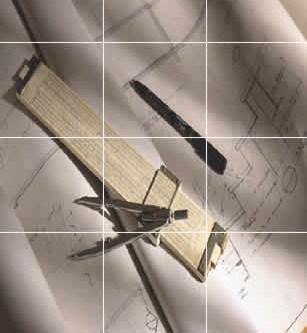
9 Create a Drawing : Using instruments Drawing instruments are used to draw straight lines, circles, and curves concisely and accurately. Drawings are usually made to scale. Example
 software is used.")
10 Create a Drawing : Using a computer Computer aided drafting (CAD) software is used. Example 2D drawing Solid modeling
11 Elements of a Drawing A clear and precise engineering drawing requires both graphics and word languages. Graphics language Describe a shape (mainly). Word language Describe an exact size, location and specification of the object.
12 Text on drawings : Example Dimensions & Notes General notes Title block
13 Knowledge and Skills Require Engineering Drawing Graphics language Word language Geometric construction Using line types Projection method Visualization Dimensions & Notes Visualization is the ability to mentally picture things that do not exists. Contents
14 Drawing Standard Drawing sheet Scale Lettering Line types Contents
15 Definition and Necessity Drawing standards are set of rules that govern how technical drawings are represented. Drawing standards are used so that drawings convey the same meaning to everyone who reads them.
16 Standard Code Country Code Full name USA Japan UK Australia Germany ANSI JIS BS AS DIN ISO American National Standard Institute Japanese Industrial Standard British Standard Australian Standard Deutsches Institut für Normung International Standards Organization
17 Drawing Standard Drawing Sheet Drawing standard Contents
18 Drawing Sheet : Standard size Trimmed paper of a size A0 ~ A4. Standard sheet size (JIS) A4 210 x 297 A3 297 x 420 A2 420 x 594 A1 594 x 841 A0 841 x 1189 (Dimensions in millimeters) A4 A3 A2 A1 A0
19 c c Drawing Sheet : Orientation & Margin 1. Type X (A0~A4) Sheet size c (min) d (min) Border lines d 2. Type Y (A4 only) Drawing space c Title block A A A A A d Drawing space Title block
20 Drawing Standard Drawing Scale Drawing standard Contents
21 Drawing Scales : Definition Length, size Scale is a ratio between the linear dimension of a drawn representation of an object and the actual object. 1 : 2 Drawing Actual
 for an enlargement scales SCALE 1:X (X > 1) for a reduction scales Drawing scale is commonly found in a title block.")
22 Drawing Scales : Designation Designation of a scale consists of the word SCALE followed by the indication of its ratio, as follows SCALE 1:1 for full size SCALE X:1 (X > 1) for an enlargement scales SCALE 1:X (X > 1) for a reduction scales Drawing scale is commonly found in a title block.
23 Drawing Scales : Notes Dimension numbers shown in the drawing represent the true size of an object and they are independent of the drawing scale used.
24 Drawing Scales : Standard scale Standard reducing scales are 1:2, 1:5, 1:10, 1:20, 1:50, 1:100 Standard enlarging scales are 2:1, 5:1, 10:1, 20:1, 50:1, 100:1
25 Drawing Standard Lettering Drawing standard Contents
26 Recommendation Text s style on the drawing must have the following 2 properties Legibility - Shape - Space between letters - Space between words Uniformity - Size (or text height) - line thickness Examples GOOD Not uniform in style. Not uniform in height. Not uniformly vertical. Not uniform in thickness of stroke. Inappropriate space between letters
27 Style (this course) Gothic vertical style. Begin the sentence, phrase or word with a capital letter. Text height 3~5 mm. Space between lines of text is about of text height. Height of the lower-case letter is about 2/3 of that of a capital letter.
28 Basic Strokes Straight Slanted Horizontal Curved Examples I letter A letter B letter

29 Suggested Upper-case Strokes Letters & Sequence Numerals Straight line letters Curved line letters & Numerals
30 Lower-case Letters
31 Stroke Sequence : Upper-case I L T F E H Skip section
32 Stroke Sequence : Upper-case V X W Skip section
33 Stroke Sequence : Upper-case N M K Z Y A 4 Skip section
34 Stroke Sequence : Upper-case O Q C G Skip section
35 Stroke Sequence : Upper-case D U P B R J Skip section
36 Stroke Sequence : Upper-case Skip section
37 Stroke Sequence : Upper-case S Skip section
38 Stroke Sequence : Lower-case l i Skip section
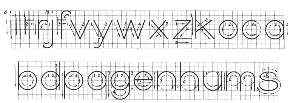
39 Stroke Sequence : Lower-case v w x k z Skip section
40 Stroke Sequence : Lower-case j y f t r Skip section
41 Stroke Sequence : Lower-case c o a b d p q e Skip section
42 Stroke Sequence : Lower-case g n m h u s Skip section
43 Word Composition Space between the letters depends on the adjacent contour of the letters. Non-uniform spacing DRAWING Uniform spacing D R A W I N G Word having Non-uniform spacing is more readable.
44 Spacing Word Composition DRAWING Contour Contour can be denoted as straight, slant and curve. Adjacent contour can be 1. straight-straight : II, IN, IM, IP etc. 2. straight-curve (or curve-straight) : IO, QR etc. 3. straight-slant (or slant-straight) : IV, IW etc. 4. curve-curve : OO, OG etc. 5. slant-curve (or curve-slant) : VO, WG, VC etc. 6. slant-slant : VW, VX etc.
45 Sentence Composition Leave the space between words equal to the space requires for writing a letter O. Example ALL O DIMENSIONS O ARE O IN MILLIMETERS O UNLESS OTHERWISE O SPECIFIED.


46 Drawing Standard Line Types Drawing standard Contents
47 Basic Line Types & Name according to application Thickness Thick Thin 1. Dimension line Style Continuous Dash Chain Visible line 2. Extension line 3. Leader line Hidden line Center line 1. Visible line 2. Dimension line Extension line Leader line represent features that can be seen in the current view. indicate the sizes and location of features. 3. Hidden line 4. Center line represent features that can not be seen in the current view. represents symmetry, path of motion, centers of circles, axis of axisymmetrical parts
48 Example Contents
Chapter 1 Overview of an Engineering Drawing
 Chapter 1 Overview of an Engineering Drawing TOPICS Graphics language Engineering drawing Projection methods Orthographic projection Drawing standards TOPICS Traditional Drawing Tools Lettering Freehand
Chapter 1 Overview of a Technical Drawing
 Chapter 1 Overview of a Technical Drawing TOPICS Graphics language Engineering drawing Projection methods Orthographic projection Drawing standards TOPICS Traditional Drawing Tools Lettering Dimensioning
CHAPTER 01 PRESENTATION OF TECHNICAL DRAWING. Prepared by: Sio Sreymean
 CHAPTER 01 PRESENTATION OF TECHNICAL DRAWING Prepared by: Sio Sreymean 2015-2016 Why do we need to study this subject? Effectiveness of Graphics Language 1. Try to write a description of this object. 2.
AutoCAD 2D-I. Module 1: Introduction to Drawing Tools. IAT Curriculum Unit PREPARED BY. January 2011
 AutoCAD 2D-I Module 1: Introduction to Drawing Tools PREPARED BY IAT Curriculum Unit January 2011 Institute of Applied Technology, 2011 Module 1: Introduction to Drawing Tools Module Objectives After
Chapter 6. Architectural Lines and Lettering
 Chapter 6 Architectural Lines and Lettering Drafting Introduction Universal graphic language Uses lines, symbols, dimensions, and notes to describe a structure to be built Properly drawn lines are dark,
Fundamentals for building Drawing
 Fundamentals for building Drawing What is Drawing Introduction Knowledge of preparing and understanding drawing will prove to be an invaluable aid while performing their jobs effectively, efficiently.
Orthographic Projection
 Orthographic Projection Why Orthographic Projection is used in technical drawing Orthographic projection is a method of producing a number of separate two-dimensional inter-related views, which are mutually
CE 100 Civil Engineering Drawing Sessional (Lab Manual)
") CE 100 Civil Engineering Drawing Sessional (Lab Manual) Department of Civil Engineering Ahsanullah University of Science and Technology November, 2017 1 Preface This course is designed to provide civil
CE 100 Civil Engineering Drawing Sessional (Lab Manual) Department of Civil Engineering Ahsanullah University of Science and Technology November, 2017 1 Preface This course is designed to provide civil
ORTHOGRAPHIC PROJECTIONS. Ms. Sicola
 ORTHOGRAPHIC PROJECTIONS Ms. Sicola Objectives List the six principal views of projection Sketch the top, front and right-side views of an object with normal, inclined, and oblique surfaces Objectives
DFTG 1305 UNIT 1. Semester: Spring 2016 Class #: Term: SS Instructor: Mays ALSabbagh
 DFTG 1305 UNIT 1 Semester: Spring 2016 Class #: 94412 Term: SS Instructor: Mays ALSabbagh Technical Drafting Unit One: Introduction to Drafting Chapter 1 : The World Wide Graphic language for Design Lecture
MISS. HANNA S CLASSROOM RULES
 MISS. HANNA S CLASSROOM RULES 1. My students never fail. I believe in you and so shall you! Miss. Hanna s Quote! 2. Come to class on time. 3. Bring a positive attitude. 4. Come prepared and bring your
Multiview Drawing. Definition: Graphical representation of a 3- dimensional object on one plane (sheet of paper) using two or more views.
 using two or more views.") Multiview Drawing Definition: Graphical representation of a 3- dimensional object on one plane (sheet of paper) using two or more views. Multiview Drawing Another name for multiview drawing is orthographic
Multiview Drawing Definition: Graphical representation of a 3- dimensional object on one plane (sheet of paper) using two or more views. Multiview Drawing Another name for multiview drawing is orthographic
Copyrighted Material. Copyrighted Material. Copyrighted. Copyrighted. Material
 Engineering Graphics ORTHOGRAPHIC PROJECTION People who work with drawings develop the ability to look at lines on paper or on a computer screen and "see" the shapes of the objects the lines represent.
CAD Mechanical Design I
 EXAM INFORMATION Items 58 Points 85 Prerequisites NONE Course Length ONE SEMESTER Career Cluster ARCHITECTURE AND CONSTRUCTION MANUFACTURING SCIENCE, TECHNOLOGY, ENGINEERING AND MATHEMATICS Performance
Student Name: Teacher: Date: District: Rowan. Assessment: 9_12 T and I IC61 - Drafting I Test 1. Description: Unit C - Sketching - Test 2.
 Student Name: Teacher: Date: District: Rowan Assessment: 9_12 T and I IC61 - Drafting I Test 1 Description: Unit C - Sketching - Test 2 Form: 501 1. The most often used combination of views includes the:
Civil Engineering Drawing
 Civil Engineering Drawing Third Angle Projection In third angle projection, front view is always drawn at the bottom, top view just above the front view, and end view, is drawn on that side of the front
Sketching in SciTech. What you need to know for graphic communication
 Sketching in SciTech What you need to know for graphic communication Sketching in your Logbook Use pencil Take up the WHOLE PAGE Label things 1. Proportion Each part of the sketch is the right size,
Guide To British Standards
 Guide To British Standards Higher Graphic Communication C O N T E N T S page TITLE BLOCK 2 DRAWING SCALES 2 LINE TYPES 3 ORTHOGRAPHIC PROJECTION 4 SECTIONAL VIEWS 4 SCREW THREADS & COMPONENTS 7 INTERUPTTED
Engineering Working Drawings Basics
 Engineering Working Drawings Basics Engineering graphics is an effective way of communicating technical ideas and it is an essential tool in engineering design where most of the design process is graphically
Chapter 8. Technical Drawings
 Chapter 8 Technical Drawing Technical Drawings Multiview drawings Also called three-view drawings Simple objects take three views Front, top, one side Title block Identifies who did the design Gives date,
ME 111: Engineering Drawing
 ME 111: Engineering Drawing Lecture # 01 Introduction For more detail, visit http://shilloi.iitg.ernet.in/~psr/ Indian Institute of Technology Guwahati Guwahati 781039 1 Syllabus 1. Importance of engineering
ORTHOGRAPHIC PROJECTION
 ORTHOGRAPHIC PROJECTION C H A P T E R S I X OBJECTIVES 1. Recognize and the symbol for third-angle projection. 2. List the six principal views of projection. 3. Understand which views show depth in a drawing
(As per New Revised Syllabus of Anna University) Department of Mechanical Engineering. SATHYABAMA UNIVERSITY Jeppiaar Nagar, Chennai
 Department of Mechanical Engineering. SATHYABAMA UNIVERSITY Jeppiaar Nagar, Chennai") (1*,1((5,1* *5$3+,&6 (As per New Revised Syllabus of Anna University) Dr. S.RAMACHANDRAN, M.E., Ph.D. Professor & Head K. PANDIAN, M.E., E.V.V.RAMANAMURTHY, M.Tech., R. DEVARAJ, M.E., Associate Professors
(1*,1((5,1* *5$3+,&6 (As per New Revised Syllabus of Anna University) Dr. S.RAMACHANDRAN, M.E., Ph.D. Professor & Head K. PANDIAN, M.E., E.V.V.RAMANAMURTHY, M.Tech., R. DEVARAJ, M.E., Associate Professors
CLASS views from detail on a grid paper. (use appropriate line types to show features) - Optional views. Turn in for grading on class 6 (06/04)
 - Optional views. Turn in for grading on class 6 (06/04)") CLASS 4 Review: - Projections - Orthographic projections Lab: - 3 views from detail on a grid paper. (use appropriate line types to show features) - Optional views. Turn in for grading on class 6 (06/04)
CLASS 4 Review: - Projections - Orthographic projections Lab: - 3 views from detail on a grid paper. (use appropriate line types to show features) - Optional views. Turn in for grading on class 6 (06/04)
TECHNICAL DESIGN I (540)
") DESCRIPTION The first assessment in a series, Technical Design I prepares students to develop technical knowledge and skills required to plan and prepare scale pictorial interpretations of engineering
DESCRIPTION The first assessment in a series, Technical Design I prepares students to develop technical knowledge and skills required to plan and prepare scale pictorial interpretations of engineering
GUIDELINES FOR DRAFTING
 UNIT 1 GUIDELINES FOR DRAFTING 1.1 Introduction The term draughting is used to describe the language of drafting in this book. It defines the terminology, symbology, conventions, and standards used in
Pictorial Drawings. DFTG-1305 Technical Drafting Prepared by Francis Ha, Instructor
 DFTG-1305 Technical Drafting Prepared by Francis Ha, Instructor Pictorial Drawings Geisecke s textbook for reference: 14 th Ed. Ch. 15: p. 601 Ch. 16: p. 620 15 th Ed. Ch. 14: p. 518 Ch. 15: p. 552 Update:
Multiviews and Auxiliary Views
 Multiviews and Auxiliary Views Multiviews and Auxiliary Views Objectives Explain orthographic and multiview projection. Identifying the six principal views. Apply standard line practices to multiviews
Brief Introduction to Engineering Graphics The use of drawings to convey information. Sketching freehand straight edge
 Brief Introduction to Engineering Graphics The use of drawings to convey information. Sketching freehand straight edge CAD drawings 2D drafting 3D model to 2D drawings 1 Different Graphical Representation
ENGINEERING GRAPHICS 1.0 Introduction Engineering Graphics Drawing as an art Artist Graphic design Engineering graphics engineering drawing
 ENGINEERING GRAPHICS 1.0 Introduction Engineering is the profession in which the knowledge of mathematics and science gained by study, experience and practice is applied with good judgment to develop a
ENGR 1182 Midterm Exam 1: Study Guide and Practice Problems
 ENGR 1182 Midterm Exam 1: Study Guide and Practice Problems Disclaimer Problems seen in this study guide may resemble problems relating mainly to the pertinent homework assignments. Reading this study
Multi-View Drawing Review
 Multi-View Drawing Review Sacramento City College EDT 300/ENGR 306 EDT 300 / ENGR 306 - Chapter 5 1 Objectives Identify and select the various views of an object. Determine the number of views needed to
Drawing sheet: - The various size of the drawing sheet used for engineering drawing as per IS Are listed in the table
 Dronacharya Group of Institutions, Greater Noida Computer Aided Engineering Graphics (CAEG) (NCE 151/251) List of Drawing Sheets: 1. Letter writing & Dimensioning. 2. Projection of Points & Lines. 3. Projection
Engineering Graphics- Basics.
 Engineering Graphics- Basics DRAWINGS: ( A Graphical Representation) The Fact about: If compared with Verbal or Written Description, Drawings offer far better idea about the Shape, Size & Appearance of
Multiview Projection
 DFTG-1305 Technical Drafting Prof. Francis Ha Session 4 Multiview Projection (or Orthographic Projection) Reading: Geisecke s textbook: 14 th Ed. Chapter 5 p.162 15 th Ed. Chapter 6 p.232 Update: 17-0510
the same information given in two different 1. Dimensions should NOT be duplicated, or Dimension Guidelines Incorrect ways.
 Dimension Guidelines 1. Dimensions should NOT be duplicated, or the same information given in two different ways. Incorrect 1. Dimensions should NOT be duplicated, or the same information given in two
At the conclusion of this unit you should be able to accomplish the following with a 70% accuracy
 7 Multiview Drawing OBJECTIVES At the conclusion of this unit you should be able to accomplish the following with a 70% accuracy 1. explain the importance of mulitview drawing as a communication tool far
Activity 5.2 Making Sketches in CAD
 Activity 5.2 Making Sketches in CAD Introduction It would be great if computer systems were advanced enough to take a mental image of an object, such as the thought of a sports car, and instantly generate
Concepts I Principles of Engineering Drawing
 Concepts I Principles of Engineering Drawing Tuesday 1 st Week Introduction Today it is common for a part to be designed in one country, manufactured in another and assembled in a third This can be done
Alphabet of Lines Chapter 3
 Alphabet of Lines Chapter 3 Sacramento City College EDT 300/ ENGR 306 EDT 300/306 - Basic Technical Drafting 1 Alphabet of Lines The design industry has agreed on a set of standard lines that are used
Chapter 2: Dimensioning Basic Topics Advanced Topics Exercises
 Chapter 2: Dimensioning Basic Topics Advanced Topics Exercises Dimensioning: Basic Topics Summary 2-1) Detailed Drawings 2-2) Learning to Dimension 2-3) Dimension Appearance and Techniques. 2-4) Dimensioning
Engineering Graphics Essentials with AutoCAD 2015 Instruction
 Kirstie Plantenberg Engineering Graphics Essentials with AutoCAD 2015 Instruction Text and Video Instruction Multimedia Disc SDC P U B L I C AT I O N S Better Textbooks. Lower Prices. www.sdcpublications.com
Engineering Graphics. Class 2 Drafting Instruments Mohammad Kilani
 Engineering Graphics Class 2 Drafting Instruments Mohammad Kilani Drafting Instruments A Design is as good as its instruments A engineering drawing is a highly stylized graphic representation of an idea.
KNOWLEDGE & INTERPRETATION
 CONTENTS DESK TOP PUBLISHING ALIGNMENT positions of text lines on a page or column e.g. aligned right, aligned left or fully justified. BLEED this is to extend an artwork graphic beyond the trimmed edge
Introduction CHAPTER Graphics: A Tool to Communicate Ideas
 CHAPTER 1 Introduction 1.1 Graphics: A Tool to Communicate Ideas Engineering graphics or drawing is the universal language of engineers. An engineer communicate his idea to others with the help of this
Technology Education Grades Drafting I
 Technology Education Grades 9-12 Drafting I 46 Grade Level: 9, 10, 11, 12 Technology Education, Grades 9-12 Drafting I Prerequisite: None Drafting I is an elective course which provides students the opportunity
ENGINEERING GRAPHICS ESSENTIALS. (A Text and Lecture Aid) Second Edition. Kirstie Plantenberg University of Detroit Mercy SDC PUBLICATIONS
 Second Edition. Kirstie Plantenberg University of Detroit Mercy SDC PUBLICATIONS") ENGINEERING GRAPHICS ESSENTIALS (A Text and Lecture Aid) Second Edition Kirstie Plantenberg University of Detroit Mercy SDC PUBLICATIONS Schroff Development Corporation www.schroff.com www.schroff-europe.com
ENGINEERING GRAPHICS ESSENTIALS (A Text and Lecture Aid) Second Edition Kirstie Plantenberg University of Detroit Mercy SDC PUBLICATIONS Schroff Development Corporation www.schroff.com www.schroff-europe.com
Beginning Engineering Graphics 3 rd Week Lecture Notes Instructor: Edward N. Locke Topic: The Coordinate System, Types of Drawings and Orthographic
 Beginning Engineering Graphics 3 rd Week Lecture Notes Instructor: Edward N. Locke Topic: The Coordinate System, Types of Drawings and Orthographic 1 st Subject: The Cartesian Coordinate System The Cartesian
Glass Box Projection. Gives you 6 sides to view of an object. 10/2/14 2
 2D Drawings Glass Box Projection Gives you 6 sides to view of an object. 10/2/14 2 We can simplify this for some objects to 3 views Glass Box Approach Glass Box Approach Glass Box Approach Glass Box Approach
Interpretation of Drawings. An Introduction to the Basic Concepts of Creating Technical Drawings
 Interpretation of Drawings An Introduction to the Basic Concepts of Creating Technical Drawings Introduction In the design process drawings are the main way in which information about an object or product
Technological Design Mr. Wadowski. Orthographic & Isometric Drawing Lesson
 Technological Design Mr. Wadowski Orthographic & Isometric Drawing Lesson TOPICS Working Drawings, Isometric Drawings & Orthographic Drawings Glass box concept Multiview projection Orthographic projection
DELHI TECHNOLOGICAL UNIVERSITY ENGINEERING GRAPHICS LAB MANUAL
 DELHI TECHNOLOGICAL UNIVERSITY ENGINEERING GRAPHICS LAB MANUAL NAME: - ROLL NO: - GROUP: - BRANCH: - GROUP TEACHER: Page 1 www.rooplalrana.com 1 GENERAL INSTRUCTIONS FOR ENGG. GRAPHICS LAB 1) Students
INTRODUCTION to CAD ACAD BASICS. 2.1 Starting with ACAD. 2.2 Layout and sketching. 2.3 Drawing environment. 2.4 Elements of drawing
 INTRODUCTION to CAD ACAD BASICS 2.1 Starting with ACAD 2.2 Layout and sketching 2.3 Drawing environment 2.4 Elements of drawing 2.4.1 Draw commands 2.5 3D functions 2.6 Starting the drawing 2.6.1 Drawing
UNIT 5a STANDARD ORTHOGRAPHIC VIEW DRAWINGS
 UNIT 5a STANDARD ORTHOGRAPHIC VIEW DRAWINGS 5.1 Introduction Orthographic views are 2D images of a 3D object obtained by viewing it from different orthogonal directions. Six principal views are possible
Production drawing Diagram. a) I am a freehand drawing that follows technical drawing standards.
 I am a freehand drawing that follows technical drawing standards.") THE TECHNOLOGICAL WORLD Graphical language STUDENT BOOK Ch. 11, pp. 336 342 Basic lines, geometric lines, sketches 1. In technology, the two most widely used types of technical drawings are: a) sketch
THE TECHNOLOGICAL WORLD Graphical language STUDENT BOOK Ch. 11, pp. 336 342 Basic lines, geometric lines, sketches 1. In technology, the two most widely used types of technical drawings are: a) sketch
DMT113 Engineering Drawing. Chapter 3 Stretch System
 DMT113 Engineering Drawing Chapter 3 Stretch System Contents Theory & Multiview Planes 6 Principle Views Multiview Sketching Technique & Perspective First & Third Angle Multiview Representations Theory
ENGINEERING GRAPHICS ESSENTIALS
 ENGINEERING GRAPHICS ESSENTIALS with AutoCAD 2012 Instruction Introduction to AutoCAD Engineering Graphics Principles Hand Sketching Text and Independent Learning CD Independent Learning CD: A Comprehensive
Student Name: Teacher: Date: District: Rowan. Assessment: 9_12 T and I IC61 - Drafting I Test 2. Description: Drafting 1 - Test 6.
 Student Name: Teacher: Date: District: Rowan Assessment: 9_12 T and I IC61 - Drafting I Test 2 Description: Drafting 1 - Test 6 Form: 501 1. 2X on a hole note means: A. Double the size of the hole. B.
ENGINEERING GRAPHICS ESSENTIALS
 ENGINEERING GRAPHICS ESSENTIALS Text and Digital Learning KIRSTIE PLANTENBERG FIFTH EDITION SDC P U B L I C AT I O N S Better Textbooks. Lower Prices. www.sdcpublications.com ACCESS CODE UNIQUE CODE INSIDE
1: Assemblage & Hierarchy
 What: 1: Assemblage & Hierarchy 2 compositional sequences o abstract, line compositions based on a 9 square grid o one symmetrical o one asymmetrical Step 1: Collage Step 2: Additional lines Step 3: Hierarchy
ENGR 1182 Exam 1 First Mid Term Exam Study Guide and Practice Problems
 Spring Semester 2016 ENGR 1182 Exam 1 First Mid Term Exam Study Guide and Practice Problems Disclaimer Problems in this study guide resemble problems relating mainly to the pertinent homework assignments.
Principles and Practice
 Principles and Practice An Integrated Approach to Engineering Graphics and AutoCAD 2011 Randy H. Shih Oregon Institute of Technology SDC PUBLICATIONS www.sdcpublications.com Schroff Development Corporation
Technical English -I 4 th week ENGINEERING DRAWING
 Technical English -I 4 th week ENGINEERING DRAWING What is engineering drawing? It is the art of representation of geometrical objects on a drawing sheet. An engineering drawing is used to fully and clearly
3. The dimensioning SYMBOLS for arcs and circles should be given:
 Draft Student Name: Teacher: District: Date: Wake County Test: 9_12 T and I IC61 - Drafting I Test 2 Description: 4.08 Dimensioning Form: 501 1. The MINIMUM amount of space between two, ADJACENT DIMENSION
TIME SCHEDULE. Module Topic Periods 1 Importance of Engineering Graphics Drawing Instruments Drawing Standards Lettering and Numbering
 COURSE TITLE : ENGINEERING GRAPHICS (First Semester) COURSE CODE : COURSE CATEGORY : F PERIODS/WEEK : 3 PERIODS/SEMESTER : 54 CREDITS : Examination in the Second Semester RATIONALE: Engineering Graphics
Reavis High School Curriculum Snapshot/Cover Page for Computer Aided Design (CAD)
") Reavis High School Curriculum Snapshot/Cover Page for Computer Aided Design (CAD) Unit 1: Introduction In this unit, students will identify components of a Computer Aided Design (CAD) system and how to
Reavis High School Curriculum Snapshot/Cover Page for Computer Aided Design (CAD) Unit 1: Introduction In this unit, students will identify components of a Computer Aided Design (CAD) system and how to
Mechanical Drawing. Unit 2 Study Guide for Chapters 6-10
 Mechanical Drawing Unit 2 Study Guide for Chapters 6-10 Chapter 6 Multiview Drawing Section 6.1 Understanding Orthographic Projection A. Technical Drawing: How can a technical drawing give more accurate
Test Code: 8294 / Version 1
 Pennsylvania Customized Assessment Blueprint Test Code: 8294 / Version 1 Copyright 2014. All Rights Reserved. General Assessment Information Blueprint Contents General Assessment Information Written Assessment
DFTG-1305 Technical Drafting Prof. Francis Ha
 DFTG-1305 Technical Drafting Prof. Francis Ha Session 5 Dimensioning Geisecke s textbook: 14 th Ed. Chapter 10 p. 362 15 th Ed. Chapter 11 p. 502 Update: 17-0508 Dimensioning Part 1 of 2 Dimensioning Summary
ORTHOGRAPHIC PROJECTION
 ORTHOGRAPHIC PROJECTION INTRODUCTION Any object has three dimensions, that is, length, width and thickness. A projection is defined as a representation of an object on a two dimensional plane. The projections
Graphical Communication
 Chapter 9 Graphical Communication mmm Becoming a fully competent engineer is a long yet rewarding process that requires the acquisition of many diverse skills and a wide body of knowledge. Learning most
11/12/2015 CHAPTER 7. Axonometric Drawings (cont.) Axonometric Drawings (cont.) Isometric Projections (cont.) 1) Axonometric Drawings
 Axonometric Drawings (cont.) Isometric Projections (cont.) 1) Axonometric Drawings") CHAPTER 7 1) Axonometric Drawings 1) Introduction Isometric & Oblique Projection Axonometric projection is a parallel projection technique used to create a pictorial drawing of an object by rotating the
CHAPTER 7 1) Axonometric Drawings 1) Introduction Isometric & Oblique Projection Axonometric projection is a parallel projection technique used to create a pictorial drawing of an object by rotating the
Orthographic Drawing (Architectural Board Drafting)
") Design and Drafting Description In this activity, the teacher will introduce orthographic projection, in which a multi-view drawing shows how the sides of an object are related to each another. Students
Design and Drafting Description In this activity, the teacher will introduce orthographic projection, in which a multi-view drawing shows how the sides of an object are related to each another. Students
2003 Academic Challenge
 Worldwide Youth in Science and Engineering 2003 Academic Challenge ENGINEERING GRAPHICS TEST - SECTIONAL Engineering Graphics Test Production Team Ryan Brown, Illinois State University Author/Team Coordinator
Chapter 5 Pictorial sketching
 Chapter 5 Pictorial sketching Contents Freehand sketching techniques Pictorial projections - Axonometric - Oblique Isometric projection vs isometric sketch Isometric sketch from an orthographic views Isometric
2010 Academic Challenge
 2010 Academic Challenge ENGINEERING GRAPHICS TEST STATE FINALS This Test Consists of 40 Questions Engineering Graphics Test Production Team Ryan K. Brown, Illinois State University Author/Team Leader Jacob
technical drawing
 technical drawing school of art, design and architecture nust spring 2011 http://www.youtube.com/watch?v=q6mk9hpxwvo http://www.youtube.com/watch?v=bnu2gb7w4qs Objective abstraction - axonometric view
ARCHITECTURAL DESIGN (542)
") DESCRIPTION This is the first assessment in a sequence, Architectural Design I prepares students with knowledge of residential architectural and related construction. Topics include; architectural blueprint
DESCRIPTION This is the first assessment in a sequence, Architectural Design I prepares students with knowledge of residential architectural and related construction. Topics include; architectural blueprint
PLAN, SECTION, ISOMETRIC: OBJECT
 ISOMETRIC #5a PLAN, ELEVATION, ISOMETRIC Draft due Monday, October 15 correct & precise Redraft with Ink Due Monday October 22 On a sheet of 18"x24" strathmore, compile a set of drawings of a small object
Chapter 5 SECTIONS OF SOLIDS 5.1 INTRODUCTION
 Chapter 5 SECTIONS OF SOLIDS 5.1 INTRODUCTION We have studied about the orthographic projections in which a 3 dimensional object is detailed in 2-dimension. These objects are simple. In engineering most
DFTG-1305 Technical Drafting Prof. Francis Ha
 DFTG-1305 Technical Drafting Prof. Francis Ha Session 4 Orthographic Projection (or Multiview Projection) Reading: Geisecke s textbook: 14 th Ed. Chapter 5 p.162 15 th Ed. Chapter 6 p.232 Update: 18-0205
SDC PUBLICATIONS. Schroff Development Corporation
 SDC PUBLICATIONS Schroff Development Corporation www.schroff.com www.schroff-europe.com SECTIONING In chapter 3 you will learn how to create various types of sectional views. Sectional views allow you
ENGINEERING DRAWING. 1. Set squares are used to draw different angles. What is the angel a formed by the 45⁰ set square? Give a brief answer.
 ENGINEERING DRAWING 1. Set squares are used to draw different angles. What is the angel a formed by the 45⁰ set square? Give a brief answer. 2. Which is the correct method of hatching a plane surface?
Unit-5 ISOMETRIC PROJECTION
 Unit-5 ISOMETRIC PROJECTION Importance Points in Isometric: 1. For drawing the isometric, the object must be viewed such that either the front -right or the left edges becomes nearest. 2. All vertical
ISOMETRIC PROJECTION. Contents. Isometric Scale. Construction of Isometric Scale. Methods to draw isometric projections/isometric views
 ISOMETRIC PROJECTION Contents Introduction Principle of Isometric Projection Isometric Scale Construction of Isometric Scale Isometric View (Isometric Drawings) Methods to draw isometric projections/isometric
UNIT Lines and Symbols
 3 UNIT Lines and Symbols Various lines on a drawing have different meanings. They may appear solid, broken, thick, or thin. Each is designed to help the blueprint reader make an interpretation. The standards
2018 Technical Drawing Specifications Resource A guide to support VCE Visual Communication Design Study Design
 2018 Technical Drawing Specifications Resource A guide to support VCE Visual Communication Design Study Design 2018 22 VICTORIAN CURRICULUM AND ASSESSMENT AUTHORITY 1 Contents A guide to support VCE Visual
ENGINEERING DRAWING LECTURE 4
 ENGINEERING DRAWING LECTURE 4 Conventions Convention or Code: The representation of any matter by some sign or mark on the drawing is known as convention or code. The convention make the drawing simple
Activity Multiview Sketches
 Activity 1.2.4 Multiview Sketches Purpose It s a very common occurrence to see a product advertisement and think, I thought of an idea for something like that just a few months ago. People spend a lot
Activity Multiview Sketches
 Activity 1.2.4 Multiview Sketches Introduction It s a very common occurrence to see a product advertisement and think, I thought of an idea for something like that just a few months ago. People spend a
Copyrighted. Material. Copyrighted. Material. Copyrighted. Copyrighted. Material
 Engineering Graphics FREEHAND SKETCHING Introduction to Freehand Sketching Sketching is a very important technique for technical communication. Sketches can transfer ideas, instructions and information
A Concise Introduction to Engineering Graphics
 A Concise Introduction to Engineering Graphics Fourth Edition Including Worksheet Series A Timothy J. Sexton, Professor Department of Industrial Technology Ohio University BONUS Book on CD: TECHNICAL GRAPHICS
ME1105 Engineering Drawing & Design
 City University London Term 1 Assessment 2008/2009 School of Engineering and Mathematical Sciences ME1105 Engineering Drawing & Design Student Name:.., Group: Examination duration: Reading time: This paper
DIMENSIONING ENGINEERING DRAWINGS
 DIMENSIONING ENGINEERING DRAWINGS An engineering drawing must be properly dimensioned in order to convey the designer s intent to the end user. Dimensions provide the information needed to specify the
ME 111: Engineering Drawing
 ME 111: Engineering Drawing Lecture 5 12-08-2011 Orthographic projection and Projection of Points Indian Institute of Technology Guwahati Guwahati 781039 1 Orthographic Projection A parallel projection
Contents. Notes on the use of this publication
 Contents Preface xxiii Scope Notes on the use of this publication xxv xxvi 1 Layout of drawings 1 1.1 General 1 1.2 Drawing sheets 1 1.3 Title block 2 1.4 Borders and frames 2 1.5 Drawing formats 2 1.6
TECHNICAL DRAWING HIGHER LEVEL PAPER II(A) ENGINEERING APPLICATIONS
 ENGINEERING APPLICATIONS") M. 84 AN ROINN OIDEACHAIS AGUS EOLAÍOCHTA LEAVING CERTIFICATE EXAMINATION, 2001 TECHNICAL DRAWING HIGHER LEVEL PAPER II(A) ENGINEERING APPLICATIONS Friday, 15 June, Afternoon 2.00 5.00 p.m. 200 Marks INSTRUCTIONS
M. 84 AN ROINN OIDEACHAIS AGUS EOLAÍOCHTA LEAVING CERTIFICATE EXAMINATION, 2001 TECHNICAL DRAWING HIGHER LEVEL PAPER II(A) ENGINEERING APPLICATIONS Friday, 15 June, Afternoon 2.00 5.00 p.m. 200 Marks INSTRUCTIONS
Geometric dimensioning & tolerancing (Part 1) KCEC 1101
 KCEC 1101") Geometric dimensioning & tolerancing (Part 1) KCEC 1101 Introduction Before an object can be built, complete information about both the size and shape of the object must be available. The exact shape of
Geometric dimensioning & tolerancing (Part 1) KCEC 1101 Introduction Before an object can be built, complete information about both the size and shape of the object must be available. The exact shape of
ENGINEERING DRAWING INTRODUCTION
 ENGINEERING DRAWING INTRODUCTION Drawing is the graphical language of engineers which is built upon certain basic principles and standards. A good drawing can be prepared making use of these principles