ENGINEERING DRAWING INTRODUCTION
|
|
|
- Zoe Fowler
- 5 years ago
- Views:
Transcription
1 ENGINEERING DRAWING INTRODUCTION Drawing is the graphical language of engineers which is built upon certain basic principles and standards. A good drawing can be prepared making use of these principles and standards. It is a graphic representation of an object, of a part of it, and is the result of creative thought by engineer or technician. Engineering drawing is a two dimensional representation of three dimensional objects. In general, it provides necessary information about the shape, size, surface quality, material, manufacturing process, etc., of the object. It is the graphic language from which a trained person can visualize objects. Drawings prepared in one country may be utilized in any other country irrespective of the language spoken. Hence, engineering drawing is called the universal language of engineers. Every first year engineering student will face enough troublesome subjects and Engineering Drawing is one of the toughest. It is very obvious to have a sound knowledge of drawing for an engineering student of any branch. Technical drawing subject does not only teach students on how to draw lines and points but it is a perfect source of communication between engineer and construction sheet to make innovative designs for better future. Engineering drawings are those drawings that found very helpful to many industries to make their productive layout on sheet of paper to get higher productivity. Students should know the drawing fundamental, abbreviations and symbols if they wish to: 1. Design any part of machinery, 2. Make changes in existing engineering drawing, 3. Sketch the invention on paper, 4. Follow a certain technical field. Technical Drawing versus Engineering Drawing: The term Technical Drawing is often interchangeably used with Engineering Drawing. However for professionals the first one is regarded as a systematic and standard visualization and representation of planes and solid regular shapes in general while the second deals with standards representation of useful objects manufactured by industrialists. These useful features are graphically represented within the industry as what is known as working drawings. The former is a prerequisite knowledge for the later. Technical Drawing is a common knowledge to all engineers and technicians while Engineering Drawing can be regarded as Machine drawing, Building drawing, Electrical drawing and so on depending on the specialization field of engineering you are dealing with. 1
2 Artistic Drawing versus Engineering Drawing: A free drawing or photography provides a general three dimension view of an object however it does not show clear information on dimensions which is feature of engineering drawing. Importance of Engineering Drawings: Essential for conveying technical information, engineering drawings are very important in mechanical, building industry designs. They are used at different stages of products design among which are solution drafting, specifications of products as well as in assembly drawings which can sometimes be delivered to the customers. Engineering Drawing is not a subject to study but it is a Graphical Language To equip students with basic skills required in engineering drawings, electrical circuit diagrams, and communication that all engineers must know about to Read, Speak and Write it.. Mr. Vasim G. Machhar 1. ENGINEERING DRAWING STANDARDS STANDARDS are sets of rules that govern how technical drawings are represented. Standards allow for the clear communication of technical ideas. Engineering drawings, being one of the many forms of technical communication, have to fulfill some accepted standards. There are various national, multinational and international standards, but the current trend in most countries is to adhere (adopt) the ISO standards. Thus for the purpose of this course, we will adhere to the ISO standards. 1.1.SIZE OF DRAWING SHEETS The ISO (International Organization for Standardization) most recommended paper sizes for technical drawings are known as A-FORMATS. Others, like the B-Series, are of lesser importance. In the A-Series, the largest size is A 0. The size of A 1 paper is half the size of A 0 while A 2 is half the size of A 1 and so forth. Note that a higher order paper size (which is always smaller in size) is obtained simply halving the preceding size along its longer side. For technical drawings A 4 is considered to be the smallest paper size. Smaller sized A-Format papers (i.e. A 5, A 6 etc) are very rarely used for technical drawings. The drawing sheet sizes are as follow DESIGNATION TRIMMED SIZE (mm) UNTRIMMED SIZE (mm) A 0 SIZE 841 x x 1230 A1 size 594 x x 880 A2 size 420 x x 625 A3 size 297 x x 450 A4 size 210 x x 330 A5 size 148 x x 240 2

3 The untrimmed size is the size of the paper on which the drawing is to be made. When the drawing is completed the paper is cut to the trimmed size. On the trimmed size a margin of 10mm on all sides is to be drawn, except for A4 and A5 where the margin is only 5 mm. Sufficient space should be left for the title block. 3
4 Drawing paper must when fixed onto the drawing board be aligned such that its top and bottom edges run parallel to the straight edge of the T-Square or the Parallel Straight Edge. If properly cut, this alignment ensures that the orthogonal edge of the drawing paper is perpendicular to the Parallel Straight Edge. In engineering drawing the preparation of drawing sheet depends to a large extent on the layout of the drawing sheet. An engineer has to keep in his mind the other aspect such as margin, title block, parts list, folding marks etc so as to facilitate the reading and interpretation of the drawing. FOLDING Only format A 4 is convenient for filling. Other formats (larger in size) exceed the size of the file and thus must be folded before filing. Drawings which that do not need fastening are fold in a logical way to give an A 4 size. However, for those drawings that must be fastened, they must be fold in a standardized way as follows. Two methods of folding of drawing sheets, one suitable for filing or binding and the other Method for keeping in filing cabinets are specified by BIS. In both the methods of folding, the Title Block is always visible. TITLE BLOCK In every engineering drawing, a Title Block is included at the bottom right-hand corner. The Title Blocks are locally standardized but should be designed in such a way that it can be easily understood. 4
5 The direction of viewing of the title block should correspond in general with that of the drawing. The title block can have a maximum length of 170 mm. The information needed in any standard Title Block is normally: o Name of the Firm/School/College o Name of the Object (Work piece) o Number of the drawing (particularly useful for reference where more than one drawing are concerned --- typically in assembly drawings) o Format of the paper used (paper size) o Scale used o Dimensioning unit (usually millimeters --- mm) o Symbol for the method of projection used o Date when the drawing was finished o Name of the draftsman (draughtsman) --- e.g. student name if it is a normal class exercise o Name of the person who checked the drawing o Remarks 5
6 Drawing sheet layout Depending on the shape and size of the object being represented on the drawing, the drawing sheet can be taken in the Portrait or Landscape position. 6

7 Important terms MARGIN A margin is provided around the sheet by drawing margin lines. The provision of margin lines will enable prints to be trimmed along margin lines. Prints after trimming would be of recommended sizes of sheets. BORDER LINES The clear working space on the drawing sheet is obtained by drawing border lines. In general practice, more space is kept on the left side for filling or binding when necessary. Borders enclosed by the edges of the trimmed sheet and the frame, limiting the drawing space, should be provided with all sheet sizes. It is recommended that these borders have a minimum width of 20 mm for the sizes A 0 and A 1 and a minimum width of 10 mm for the sizes A 2, A 3 and A 4. A filing margin for taking perforations, may be provided on the edge, and far left of the title block. SOME DRAWING INSTRUMENTS AND MATERIALS Drawing Instruments are used to prepare neat and accurate Drawings. To a greater extent, the accuracy of the Drawings depends on the quality of instruments used to prepare them. The following is the list of Drawing Instruments and other materials required. a) Drawing Board b) T-square or Drafter (Drafting machine) c) Set Squares d) Protractor e) Drawing Instrument Box f) Drawing Sheet g) Drawing Pencils h) Drawing Pins/Clips a) Drawing Board: Drawing board is made from strips of well seasoned soft wood generally 25 mm thick. It is 7

8 cleared at the back by two battens to prevent warping. One of the shorter edges of the rectangular board is provided with perfectly straight ebony edge which is used as working edge on which the T-square is moved while making Drawings. Drawing board size: Drawing boards are made in various sizes. The selection of Drawing board depends on the size of drawing paper used. The sizes of Drawing board recommended are given below Standard size of Drawing boards Designation Size (mm) Designation Size (mm) B B B B B b) T-square : A T-square consists of two parts namely the stock and the blade joined together at right angles to each other by means of screws and Pins as shown in figure 1A.2. This is one of the oldest drawing instruments that still finds wide spread use both in the industry and in schools. The stock is made to slide along the working edge and the Blade moves on the Drawing board. The working edge of T-square is used to draw parallel lines, vertical lines or inclined lines at 30, 60 o to the horizontal using set squares. It helps in drawing reference lines. A good Tee square should be able to move freely on the drawing board and hold fixed, while lines are being drawn to allow proper alignment. The size of a T-Square is determined by its blade length. Blade lengths of 60-mm, 90-mm, 120- mm and 150-mm are common. USES: - The T-Square is used primarily as a guide for drawing horizontal parallel lines. -.It can also be used when drawing inclined lines, just like any other rule. 8


 Set Squares : Set squares are generally made from Plastic or celluloid material.")
9 Drafting machine (or Drafter): In a Drafting machine, the uses and advantages of T-square, set square, scales, protractors are combined. One end of the Drafter is clamped at the left top end of the Drawing board by a screw provided in the drafter. An adjustable head with a Protractor is fitted at the other end of the Drafter. Two blades made of transparent celluloid material are fitted to the adjustable head and are perfectly perpendicular to each other. These blades are used to draw parallel, horizontal, vertical and inclined lines. The blades always move parallel to the edges of the board. Use of drafting machine helps in reducing the time required to prepare Drawing. c) Set Squares : Set squares are generally made from Plastic or celluloid material. They are triangular in shape with one corner, a right angle, and triangle. A pair of set squares (30 60 ) and 45 (45 set square are generally provided with Protractor) facilitate marking of angles as shown in figures 1A.4 and 1A.5. They are used to draw lines at 30, 60 and 45 to the vertical and horizontal. 9
 and are made of Plastic or celluloid which has more life.")
 Drawing Instrument Box: It consists of the following a) Large size compasses, b) Large size divider, c) Small size")

10 d) Protractor: Protractors are used to mark or measure angles between 0 and 180. They are semicircular in shape (of diameter 100mm) and are made of Plastic or celluloid which has more life. Protractors with circular shape capable of marking and measuring 0 to 360 are also available in the market. e) Drawing Instrument Box: It consists of the following a) Large size compasses, b) Large size divider, c) Small size bow pen, bow divider, and d) Lengthening bar f) Drawing sheet: They are available in many varieties and good quality paper with smooth surface should be selected for Drawings which are to be preserved for longer time. Standard size of Drawing sheet Designation Size (mm) Designation Size (mm) 10
11 A A A A A A g) Drawing Pencils: Pencils: They are in nine grades of hardness H and six grades of blackness B. There are also two other grades: F (Firm) and HB. Two pencils are advisable for drawing with instruments 2H and 3H while HB is advisable for freehand drawing. For pencils to be used with instruments, it is advisable to sharpen them to chisel point or sided-shaped. Pencils to be used for freehand drawing should be shaped to round point. B=Black HB=Hard- Black F=Firm H=Hard 3B 2B B HB F H 2H 3H Softer Harder Lead-mine pens: They have appropriate line thickness for engineering drawings and are more suitable to use in the long run because you can use the lead until the very end. They do not have to be sharpened; the drawn lines always have the same thickness. 0.5 and 0.7mm are suitable to do the work. Lead-mine pens are really recommended for good drawing. Ink pen: They ensure exact, edge sharp and always even line thickness. Three of different line thickness can well do the job. Ink bottles or cartridge are necessary when these are being used. 11

 Drawing Pins and clips: These are used to fix the Drawing sheet on the Drawing board. Compasses and dividers They are used to draw circles.")
12 The accuracy and appearance of a Drawing depends on the quality of Pencil used to make Drawing. The grade of a Pencil lead is marked on the Pencil. HB denotes medium grade. Increase in hardness is shown by value put in front of H such as 2H, 3H etc., Softer pencils are marked as 2B, 3B, 4B etc. A Pencil marked 3B is softer than 2B and Pencil marked 4B is softer than 3B and so on. Beginning of a Drawing may be made with H or 2H. For lettering and dimensioning, H and HB Pencils are used. h) Drawing Pins and clips: These are used to fix the Drawing sheet on the Drawing board. Compasses and dividers They are used to draw circles. A good quality pair of compasses which can draw circles up to 150 mm radius is an essential item of equipment. Although not absolutely essential a pair of dividers can prove to be of use at times, when measuring from another drawing to determine an unknown dimension. Compass with knee joints should have legs bent to be perpendicular to the paper and the needle with the same length as the lead. For compass without knee joint, the lead should be adjusted to be a bit shorter than the needle or steel point to have good quality of the circle. The lead should always be sided-shaped. The sharpened side of the lead should always be on the outer side from the center of the circle. To draw a circle, put the needle in the circular center point and turn the compass handle between thumb and forefinger. 12
13 Compass is used for drawing circles and arcs of circles. The compass has two legs hinged at one end. One of the legs has a pointed needle fitted at the lower end where as the other end has provision for inserting pencil lead. Circles up to 120mm diameters are drawn by keeping the legs of compass straight. For drawing circles more than 150 mm radius, a lengthening bar is used. It is advisable to keep the needle end about 1mm long compared to that of pencil end so that while drawing circles, when the needle end is pressed it goes inside the drawing sheet by a small distance (approximately 1mm). Refer fig. 1A.8. Erasers Essential for correcting mistakes. Vinyl erasers are preferable to rubber erasers. They make cleaner job of rubbing out. Be careful of rubber dust formed when erasing from a pencil drawing. It can be a source of annoyance causing smudges on your drawings if it is allowed to accumulate. SCALES AND DIMENSIONS SCALES: The objects we encounter in our day-to-day life are usually either too large or too small to be drawn to their true size. For instance a car or a building can be drawn to its true size if, and only if, we use a piece of paper that is large enough to accommodate the true dimensions of that car or building. 13

14 In engineering drawing it is not always possible to represent the work-piece in its natural size. Therefore larger work-pieces are reduced and smaller work-piece enlarged. The standard of the reduced or enlarged scale is expressed by respective ratio. But as we have noted above, the largest size of paper (under ISO standard) is A 0 (841-mm X 1189-mm), which is a lot smaller than these objects. The discrepancy between the actual sizes of objects and the size of the papers we use for drawing necessitates us to prepare drawings that are either smaller or bigger in size than the actual objects. This is only possible through the use of scales. A scale is simply the ratio of the linear dimension appearing on the drawing compared to the corresponding linear dimension on the object A scale has no units as it is simply a ratio (i.e. dimension on drawing : dimension on object) Scales are used either for enlargements or reductions. The recommended scales in Engineering Drawing are The scale of 1:1 (read as one-to-one) implies the object has been drawn to true size. A scale of say 2:1 (read as two-to-one) implies that the object has been enlarged twice its true size. A scale of 1:2 (read as one-to-two) implies that the object has been reduced to its half size, etc. SCALE SPESFICATION If all drawings are made to the same scale, the scale should be indicated in or near the title block. Where it is necessary to use more than one scale on a drawing, the main scale only should be shown in the title block and all the other scales, adjacent to the item reference number of the part concerned or near the drawings. 14
15 DIMENSIONING Drawing of a component, in addition to providing complete shape description, must also furnish information regarding the size description. These are provided through the distances between the surfaces, location of holes, nature of surface finish, type of material, etc. The expression of these features on a drawing, using lines, symbols, figures and notes is called dimensioning. To enable productions of machine parts/components, all the relevant dimensions have to appear on the drawing. The practice is that any dimension is shown only once in that view in which it appears more explicitly. For this reason, it is not surprising that most of the important dimensions appear in the front view. Repetitions are discouraged unless clarity necessitates this. To keep the drawing clean, it is advised to put all the dimensions outside the drawing, except where and when this is unavoidable. i) Dimension lines in drawing should be placed as far as possible the outline of view. ii) All dimensions should be placed above their respective dimension lines and normal to the lines such that these can be easily read from the bottom or right side of the drawing sheet. iii) Dimension lines should not cut each other. Smaller dimensions should be placed first, that is, the dimension should be marked in the ascending order. iv) Dimension lines are never shown dotted. v) Dimensions must only given once and not be repeated on other views. vi) Holes are dimensioned by stating their diameters There are usually three representations as follows: 15
16 After carefully examining the dimensions of the object to be drawn, the student should choose a proper scale such that the drawn object will fit on the paper and he will not face a lot of calculations during drawing. When dimensions are indicated on a scaled object, true dimension should be written so that the leader will have not to make an effort of multiplying the printed dimensions and the scale to get the real size of the object. The drawn figure should be having enough but no redundant dimensions so that the reader won t get involved in complex calculation for getting unspecified dimensions. 16

. 5.")
17 PRINCIPLES OF DIMENSIONING Some of the basic principles of dimensioning are given below. 1. All dimensional information necessary to describe a component clearly and completely shall be written directly on a drawing. 2. Each feature shall be dimensioned once only on a drawing, i.e., dimension marked in one view need not be repeated in another view. 3. Dimension should be placed on the view where the shape is best seen (Fig.2.14) 4. As far as possible, dimensions should be expressed in one unit only preferably in millimeters, without showing the unit symbol (mm). 5. As far as possible dimensions should be placed outside the view (Fig.2.15). 6. Dimensions should be taken from visible outlines rather than from hidden lines (Fig.2.16). 1. As far as possible, dimensions should be placed outside the view. 17
18 2. Dimensions should be taken from visible outlines rather than from hidden lines. 3. Dimensioning to a centre line should be avoided except when the centre line passes through the centre of a hole. 4. Each feature should be dimensioned once only on a drawing. 5. Dimensions should be placed on the view or section that relates most clearly to the corresponding features. 6. Each drawing should use the same unit for all dimensions, but without showing the unit symbol. 7. No more dimensions than are necessary to define a part should be shown on a drawing. 8. No features of a part should be defined by more than one dimension in any one direction. EXECUTION METHODS The elements of dimensioning include the projection line, dimension line, leader line, dimension line termination, the origin indication and the dimension itself. The various elements of dimensioning are shown in Figs and The following are some of the principles to be adopted during execution of dimensioning: 1. Projection and dimension lines should be drawn as thin continuous lines. 2. Projection lines should extend slightly beyond the respective dimension lines. 3. Projection lines should be drawn perpendicular to the feature being dimensioned. Where necessary, they may be drawn obliquely, but parallel to each other (Fig. 2.30). However, they must be in contact with the feature. 4. Projection lines and dimension lines should not cross each other, unless it is unavoidable (Fig. 2.31). 5. A dimension line should be shown unbroken, even where the feature to which it refers, is shown broken (Fig. 2.32). 18
19 6. A centre line or the outline of a part should not be used as a dimension line, but may be used in place of projection line (Fig. 2.31). TERMINATION AND ORGIN INDICATOR Dimension lines should show distinct termination, in the form of arrow heads or oblique strokes or where applicable, an origin indication. Two dimension line terminations and an origin indication are shown in Fig In this, 1. the arrow head is drawn as short lines, having an included angle of 15, which is closed and filled-in. 2. the oblique stroke is drawn as a short line, inclined at the origin indication is drawn as a small open circle of approximately 3 mm in diameter. The size of the terminations should be proportionate to the size of the drawing on which they are used. Where space is limited, arrow head termination may be shown outside the intended limits of the dimension line that is extended for that purpose. In certain other cases, an oblique stroke or a dot may be substituted (Fig. 2.34). Where a radius is dimensioned, only one arrow head termination, with its point on the arc end of the dimension line, should be used (Fig. 2.35). However, the arrow head termination may be either on the inside or outside of the feature outline, depending upon the size of feature. 19
20 METHODS OF INDICATING DIMENSIONS Dimensions should be shown on drawings in characters of sufficient size, to ensure complete legibility. They should be placed in such a way that they are not crossed or separated by any other line on the drawing. Dimensions should be indicated on a drawing, according to one of the following two methods. However, only one method should be used on any one drawing. METHOD 1 (Aligned System) Dimensions should be placed parallel to their dimension lines and preferably near the middle, above and clear-off the dimension line (Fig. 2.36). An exception may be made where superimposed running dimensions are used (Fig b) Dimensions may be written so that they can be read from the bottom or from the right side of the drawing. Dimensions on oblique dimension lines should be oriented as shown in Fig Angular dimensions may be oriented as shown in Fig METHOD 2 (Uni-directional System) Dimensons should be indicated so that they can be read from the bottom of the drawing only. Non-horizontal dimension lines are interrupted, preferably near the middle, for insertion of the dimension (Fig. 2.39). Angular dimensions may be oriented as in Fig
 or (ii) at the end of a leader line, which terminates on a dimension line, that is too short to permit normal dimension placement (Fig. 2.")
 should be underlined as shown in Fig. 2.41.")
21 Dimensions can be, (i) above the extension of the dimension line, beyond one of the terminations, where space is limited (Fig. 2.34) or (ii) at the end of a leader line, which terminates on a dimension line, that is too short to permit normal dimension placement (Fig. 2.34) or (iii) above a horizontal extension of a dimension line, where space does not allow placement at the interruption of a non-horizontal dimension line (Fig. 2.41). Values of dimensions, out of scale (except where break lines are used) should be underlined as shown in Fig The following indications (symbols) are used with dimensions to reveal the shape identification and to improve drawing interpretation. The symbol should precede the dimensions (Fig. 2.42). S : Spherical diameter R: Radius SR: Spherical radius : Square ARRANGEMENT OF DIMENSION The arrangement of dimensions on a drawing must indicate clearly the design purpose. The following are the ways of arranging the dimensions. 21
22 CHAIN DIMENSION Chains of single dimensions should be used only where the possible accumulation of tolerances does not endanger the functional requirement of the part PARALLEL DIMENSION In parallel dimensioning, a number of dimension lines, parallel to one another and spaced-out are used. This method is used where a number of dimensions have a common datum feature SUPER IMPOSED RUNNING DIMENSION These are simplified parallel dimensions and may be used where there are space limitations COMBINED DIMENSION These are the result of simultaneous use of chain and parallel dimensions 22
23 CO-ORDINATE DIMENSION The sizes of the holes and their co-ordinates may be indicated directly on the drawing; or they may be conveniently presented in a tabular form as shown. SPECIAL INDICATIONS DIAMETERS Diameters should be dimensioned on the most appropriate view to ensure clarity. The dimension value should be preceded by. Figure shows the method of dimensioning diameters. 23
24 CORDS, ARCS, ANGLES AND RADII The dimensioning of chords, arcs and angles should be as shown in the following figure. Where the centre of an arc falls outside the limits of the space available, the dimension line of the radius should be broken or interrupted according to whether or not it is necessary to locate the centre. Where the size of the radius can be derived from other dimensions, it may be indicated by a radius arrow and the symbol R, without an indication of the value CHAMFERS AND COUNTERSUNKS Chamfers and countersunks may be dimensioned as shown in the following Figures. SCREW THREADS Screw threads are always specified with proper designation. The nominal diameter is preceded by the letter M. The useful length of the threaded portion only should be dimensioned as shown in Figure. While dimensioning the internal threads, the length of the drilled hole should also be dimensioned. 24
25 TAPERED FEATURES Tapered features are dimensioned, either by specifying the diameters at either end and the length, or the length, one of the diameters and the taper or the taper angle (a). A slope or flat taper is defined as the rise per unit length and is dimensioned by the ratio of the difference between the heights to its length (b). NOTES Notes should always be written horizontally in capital letters and begin above the leader line and may end below also. Further, notes should be brief and clear and the wording should be standard in form. The standard forms of notes and the method of indication, for typical cases are shown bellow. 25
26 26
27 The meaning of the notes given in above figures 27
28 Draughting abbreviations EXAMPLE Violations of some of the principles of drawing are indicated in Fig. a. The corrected version is given in Fig. b and the reasons are given below: 1. Dimension should follow the shape symbol. 2. and 3. As far as possible, features should not be used as extension lines for dimensioning. 4. Extension line should touch the feature. 28
29 5. Extension line should project beyond the dimension line. 6. Writing the dimension is not as per the aligned system. 7. Hidden lines should meet without a gap. 8. Centre line representation is wrong. Dot should be replaced by a small dash. 9. Horizontal dimension line should not be broken to insert the value of the dimension. 10. Dimension should be placed above the dimension line. 11. Radius symbol should precede the dimension 12. Centre lines should cross at long dashes. 13. Dimension should be written by symbol (not abbreviation) followed by its value. 14. Note with dimensions should be written in capitals. 15. Elevation is not the correct usage. 16. Usage of the term plan is obsolete in graphic language. 29
30 LINES Lines of different types and thicknesses are used for graphical representation of objects. These lines differ in (i) thickness and (ii) style. The types Typical uses of these lines are summarized below. TYPES OF LINES AND THEIR APPLICATION 30
31 Application of lines THICKNESS OR WIDTH OF LINES Application of lines Two thicknesses of lines are used in drafting practice. The ratio of the thick to thin line should not be less than 2:1. The thickness of lines should be chosen according to the size and type of the drawing from the following range: 0.18, 0.25, 0.35, 0.5, 0.7, 1, 1.4 and 2 31
32 It is recommended that the space between two parallel lines, including hatching, should never be less than 0.7 mm. ORDER OF PRIORITY OF COINCINDING LINES When two or more lines of different types coincide, the following order of priority should be observed: (i) Visible outlines and edges (Continuous thick lines, type A), (ii) Hidden outlines and edges (Dashed line, type E or F), (iii) Cutting planes (Chain thin, thick at ends and changes of cutting planes, type H), (iv) Centre lines and lines of symmetry (Chain thin line, type G), (v) Centroïdal lines (Chain thin double dashed line, type K), (vi) Projection lines (Continuous thin line, type B). The invisible line technique and axis representation should be followed as per the recommendations given in following Table. 32
33 INVISIBLE LINES AXIS LINES 33
34 TERMINATION OF LEADER LINES A leader is a line referring to a feature (dimension, object, outline, etc.). Leader lines should terminate, a) with a dot, if they end within the outlines of an object, b) with an arrow head, if they end on the outline of an object, c) without dot or arrow head, if they end on a dimension line. It is common practice to omit hidden lines in an assembled view, when their use tends to confuse an already complex drawing or when the feature is sufficiently clear in another view; but it is not advisable for a beginner to do the same and he will have to show the hidden lines in his drawing practice. Precedence of Lines 1. When a Visible Line coincides with a Hidden Line or Center Line, draw the Visible Line. 34
35 Also, extend the Center Line beyond the outlines of the view. 2. When a Hidden Line coincides with a Center Line, draw the Hidden Line. 3. When a Visible Line coincides with a Cutting Plane, draw the Visible Line. 4. When a Center line coincides with a Cutting Plane, draw the Center Line and show the Cutting Plane line outside the outlines of the view at the ends of the Center Line by thick dashes. LETTERING Lettering is the art of writing alphabets A, B, C D Z and numbers 1, 2, 3, 4, 0. Lettering is used to describe various parts of the drawing and to also provide other details as may be contained in the title box. Briefly Lettering is used to provide on the drawing, those information that cannot be provided by lines like notes, dimensions and specifications. IMPORTANCE OF LETTERING To undertake production work of engineering components as per the drawing, the size and other details are indicated on the drawing. This is done in the form of notes and dimensions. Main Features of Lettering is legibility, uniformity and rapidity of execution. Use of drawing instruments for lettering consumes more time. Lettering should be done freehand with speed. Practice accompanied by continuous efforts would improve the lettering skill and style. Poor lettering mars the appearance of an otherwise good drawing. Lettering used in engineering drawing is referred to as a Single Stroke, Commercial Gothic. The main advantage of this font is that it is easy to read. This makes the information on engineering drawing easy to understand. The letters can be made either freehand or by use of lettering devices. The general construction of vertical gothic letters and numerals is shown here after. Single Stroke Letters The word single-stroke should not be taken to mean that the lettering should be made in one stroke without lifting the pencil. It means that the thickness of the letter should be unifonn as if it is obtained in one stroke of the pencil. Types of Single Stroke Letters 1. Lettering Type A: (i) Vertical and (ii) Sloped (at 75 0 to the horizontal) 2. Lettering Type B: (i) Vertical and (ii) Sloped (at 75 0 to the horizontal) Type B Preferred In Type A, height of the capital letter is divided into 14 equal parts, while in Type B, height of the capital letter is divided into 10 equal parts. Type B is preferred for easy and fast execution, because of the division of height into 10 equal parts. 35
 letters are used for abbreviations like mm, cm, etc.")
36 Vertical Letters Preferred Vertical letters are preferred for easy and fast execution, instead of sloped letters. Note: Lettering in drawing should be in CAPITALS (i.e., Upper-case letters). Lower-case (small) letters are used for abbreviations like mm, cm, etc. SIZE OF LETTERS The following specifications are given for the dimensions of letters and numerals: i) The height of capital letters is taken as the base of dimensioning. ii) The two standard ratios for d/h, 1/14 and 1/10 are the most economical, as they result in a minimum number of line thicknesses. iii) The lettering may be inclined at 15 to the right, or may be vertical. TYPE A NOTE The spacing between two characters may be reduced by half, if this gives a better visual effect as for example LA, TV; it then equals the line thickness. 36
 = C 2 = c 2 = h Ratio of height to width for lower-case letters with stem or tail = 10:5 Height of lower-case letters without")
37 TYPE B CAPITAL Letters Ratio of height to width for most of the CAPITAL letters is approximately = 10:6 However, for M and W, the ratio = 10:8 for I the ratio = 10:2 Lower-case Letters Height of lower-case letters with stem I tail (b, d, f, g, h, j, k, I, p, q, t, y) = C 2 = c 2 = h Ratio of height to width for lower-case letters with stem or tail = 10:5 Height of lower-case letters without stem or tail c1 is approximately = (7/10) h 37
38 Ratio of height to width for most lower-case letters without stem or tail = 7: 5 However, for m and w, the ratio = 7: 7. For I and I, the ratio = 10:2 Numerals For numerals 0 to 9, the ratio of height to width = 10: 5. For I, ratio = 10: 2 Spacing Spacing between characters = a = (2/10)h Spacing between words = e = (6/10)h Hints on Lettering To save time, use a guide lining device The recommended height of lettering is 3-mm During initial learning period, make a point of concentrating on hand control Endeavor to make your hand do what you want it to do and not otherwise. Remember your fingers are not used to such movements, so they have to be trained until hand control becomes effortless Do not guess at the construction of letters and numerals. Use the sample letter Make letters and numerals as wide as they are high with individual letters of a word almost touching Spacing between words is a matter of judgment and tends to improve with practice Lines of lettering should be spaced the same distance apart Do not attempt to erase guide lines after lettering has been completed GEOMETRY Plane and Solid Geometry Plane geometry: is the study of two dimensional objects. The objects dealt with plane geometry are specified with their height and width. Since engineering drawing deals mainly with points and lines it is good to have a note on them. Point: It is a non dimensional geometric element it occurs by intersection of at least two lines. A point has no dimensions, only location Line 1 Line 2 A point 38

39 Line: It is a one dimensional geometrical element occurred by moving a point along a certain direction. There are basically vertical lines, horizontal lines and inclined lines. A line is one-dimensional A horizontal line A vertical line An inclined line Lines used in engineering drawings are specified according to their continuity and thickness. Plane: It is a geometrical figure that occurs by a connection of at least three points or a connection of a point and a line. A plane is a two dimensional figure. When the number of elements forming a plane increases, shape and name of the figure will change. A plane is two dimensional The connection of three points at a certain conditions forms triangle. The connection of four points at a certain conditions forms square. The connection of infinite points at a certain conditions forms circle. Drawing Lines Lines are drawing with the help of rulers, set square and pencils. When drawing a line, it is a good practice to keep his pencil vertical and starting from one point you slide it towards the other end. Once a line is drawn, experts never go through the drawn line once again. Dividing a line into parts of equal length 39

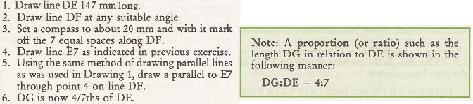
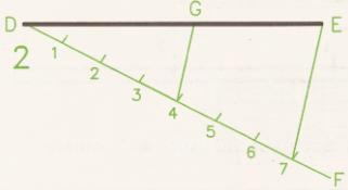
40 Dividing a line into proportional parts 40

41 41

 with each other. 42")
42 DRAWING PERPENDICULAR LINES Two lines are perpendicular to each other if they are at right angle (90 degrees) with each other. 42
43 43
44 To bisect a given angle AOB 1. With centre O, draw an arc to cut OA at C and OB at D. 2. With centres C and D, draw equal radii to intersect at E. 3. Line OE bisects angle AOB. To bisect a given straight line AB 1. With centre A and radius greater than half AB, describe an arc. 2. Repeat with the same radius from B, the arcs intersecting at C and D. 3. Join C to D and this line will be perpendicular to and bisect AB. To bisect a given arc AB 1. With centre A and radius greater than half AB, describe an arc. 2. Repeat with the same radius from B, the arcs intersecting at C and D. 3. Join C to D to bisect the arc AB. 44
45 To find the centre of a given arc AB 1. Draw two chords, AC and BD. 2. Bisect AC and BD as shown; the bisectors will intersect at E. 3. The centre of the arc is point E. To inscribe a circle in a given triangle ABC 1. Bisect any two of the angles as shown so that the bisectors intersect at D. 2. The centre of the inscribed circle is point D. To circumscribe a circle around triangle ABC 1. Bisect any two of the sides of the triangle as shown, so that the bisectors intersect at D. 2. The centre of the circumscribing circle is point D. To draw a hexagon, given the distance across the corners Method A 1. Draw vertical and horizontal centre lines and a circle with a diameter equal to the given distance. 2. Step off the radius around the circle to give six equally spaced points, and join the points to give the required hexagon. 45
46 Method B 1. Draw vertical and horizontal centre lines and a circle with a diameter equal to the given distance. 2. With a 60 set-square, draw points on the circumference 60 apart. 3. Connect these six points by straight lines to give the required hexagon. To draw a hexagon, given the distance across the flats 1. Draw vertical and horizontal centre lines and a circle with a diameter equal to the given distance. 2. Use a 60 set-square and tee-square as shown, to give the six sides. To draw a regular octagon, given the distance across corners Repeat the instructions in (b) but use a 45 setsquare, and then connect the eight points to give the required octagon. 46
47 To draw a regular octagon, given the distance across the flats Repeat the instructions in to draw a hexagon, given the distance across the flats but use a 45 setsquare to give the required octagon. To draw a regular polygon, given the length of the sides (Fig. 9.11) Note that a regular polygon is defined as a plane figure which is bounded by straight lines of equal length and which contains angles of equal size. Assume the number of sides is seven in this example. 1. Draw the given length of one side AB, and with radius AB describe a semi-circle. 2. Divide the semi-circle into seven equal angles, using a protractor, and through the second division from the left join line A2. 3. Draw radial lines from A through points 3, 4, 5, and With radius AB and centre on point 2, describe an arc to meet the extension of line A3, shown here as point F. 5. Repeat with radius AB and centre F to meet the extension of line A4 at E. 6. Connect the points as shown, to complete the required polygon. 47
48 TANGENCY If a disc stands on its edge on a flat surface it will touch the surface at one point. This point is known as the point of tangency, as shown in the following Figure and the straight line which represents the flat plane is known as a tangent. A line drawn from the point of tangency to the centre of the disc is called a normal, and the tangent makes an angle of 90 with the normal. 48

49 The following constructions show the methods of drawing tangents in various circumstances. To draw a tangent to a point A on the circumference of a circle, centre O 49
50 Join OA and extend the line for a short distance. Erect a perpendicular at point A by the method shown. To draw a tangent to a circle from any given point A outside the circle Join A to the centre of the circle O. Bisect line AO so that point B is the mid-point of AO. With centre B, draw a semi-circle to intersect the given circle at point C. Line AC is the required tangent. To draw an external tangent to two circles Join the centres of the circles by line AB, bisect AB, and draw a semi-circle. Position point E so that DE is equal to the radius of the smaller circle. Draw radius AE to cut the semi-circle at point G. Draw line AGH so that H lies on the circumference of the larger circle. Note that angle AGB lies in a semi-circle and will be 90. Draw line HJ parallel to BG. Line HJ will be tangential to the two circles and lines BJ and AGH are the normals. To draw an internal tangent to two circles Join the centres of the circles by line AB, bisect AB and draw a semi-circle. Position point E so that DE is equal to the radius of the smaller circle BC. Draw radius AE to cut the semi-circle in H. Join AH; this line crosses the larger circle circumference at J. Draw line BH. From J draw a line parallel to BH to touch the smaller circle at K. Line JK is the required tangent. 50
51 Note that angle AHB lies in a semi-circle and will therefore be 90. AJ and BK are normals. To draw internal and external tangents to two circles of equal diameter (Fig. 9.17) Join the centres of both circles by line AB. Erect perpendiculars at points A and B to touch the circumferences of the circles at points C and D. Line CD will be the external tangent. Bisect line AB to give point E, then bisect BE to give point G. With radius BG, describe a semi-circle to cut the circumference of one of the given circles at H. Join HE and extend it to touch the circumference of the other circle at J. Line HEJ is the required tangent. Note that again the angle in the semi-circle, BHE, will be 90, and hence BH and AJ are normals. To draw a curve of given radius to touch two circles when the circles are outside the radius Assume that the radii of the given circles are 20 and 25 mm, spaced 85 mm apart, and that the radius to touch them is 40 mm. With centre A. describe an arc equal to = 60 mm. With centre B, describe an arc equal to = 65 mm. The above arcs intersect at point C. With a radius of 40 mm, describe an arc from point C as shown, and note that the points of tangency between the arcs lie along the lines joining the centres AC and BC. It is particularly important to note the position of the points of tangency before lining in engineering drawings, so that the exact length of an arc can be established. 51
52 To draw a curve of given radius to touch two circles when the circles are inside the radius Assume that the radii of the given circles are 22 and 26 mm, spaced 86 mm apart, and that the radius to touch them is 100 mm. With centre A, describe an arc equal to = 78 mm. With centre B, describe an arc equal to = 74 mm. The above arcs intersect at point C. With a radius of 100 mm, describe an arc from point C, and note that in this case the points of tangency lie along line CA extended to D and along line CB extended to E. To draw a radius to join a straight line and a given circle Assume that the radius of the given circle is 20 mm and that the joining radius is 22 mm. With centre A, describe an arc equal to = 42 mm. Draw a line parallel to the given straight line and at a perpendicular distance of 22 mm from it, to intersect the arc at point B. With centre B, describe the required radius of 22 mm, and note that one point of tangency lies on the line AB at C; the other lies at point D such that BD is at 90 to the straight line. 52
53 To draw a radius which is tangential to given straight lines Assume that a radius of 25 mm is required to touch the lines shown in the figures. Draw lines parallel to the given straight lines and at a perpendicular distance of 25 mm from them to intersect at points A. As above, note that the points of tangency are obtained by drawing perpendiculars through the point A to the straight lines in each case. 53

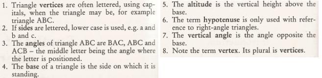
54 SURFACES TRIANGLES Definition: A triangle is a closed geometric figure having three sides and three angles. Types Terminology 54
55 A solid is three-dimensional 55
DRAWING INSTRUMENTS AND THEIR USES
 Chapter - 1A DRAWING INSTRUMENTS AND THEIR USES Drawing Instruments are used to prepare neat and accurate Drawings. To a greater extent, the accuracy of the Drawings depend on the quality of instruments
Introduction CHAPTER Graphics: A Tool to Communicate Ideas
 CHAPTER 1 Introduction 1.1 Graphics: A Tool to Communicate Ideas Engineering graphics or drawing is the universal language of engineers. An engineer communicate his idea to others with the help of this
Engineering Graphics- Basics.
 Engineering Graphics- Basics DRAWINGS: ( A Graphical Representation) The Fact about: If compared with Verbal or Written Description, Drawings offer far better idea about the Shape, Size & Appearance of
Engineering Graphics. Class 2 Drafting Instruments Mohammad Kilani
 Engineering Graphics Class 2 Drafting Instruments Mohammad Kilani Drafting Instruments A Design is as good as its instruments A engineering drawing is a highly stylized graphic representation of an idea.
ENGINEERING GRAPHICS ESSENTIALS. (A Text and Lecture Aid) Second Edition. Kirstie Plantenberg University of Detroit Mercy SDC PUBLICATIONS
 Second Edition. Kirstie Plantenberg University of Detroit Mercy SDC PUBLICATIONS") ENGINEERING GRAPHICS ESSENTIALS (A Text and Lecture Aid) Second Edition Kirstie Plantenberg University of Detroit Mercy SDC PUBLICATIONS Schroff Development Corporation www.schroff.com www.schroff-europe.com
ENGINEERING GRAPHICS ESSENTIALS (A Text and Lecture Aid) Second Edition Kirstie Plantenberg University of Detroit Mercy SDC PUBLICATIONS Schroff Development Corporation www.schroff.com www.schroff-europe.com
AutoCAD 2D-I. Module 1: Introduction to Drawing Tools. IAT Curriculum Unit PREPARED BY. January 2011
 AutoCAD 2D-I Module 1: Introduction to Drawing Tools PREPARED BY IAT Curriculum Unit January 2011 Institute of Applied Technology, 2011 Module 1: Introduction to Drawing Tools Module Objectives After
(As per New Revised Syllabus of Anna University) Department of Mechanical Engineering. SATHYABAMA UNIVERSITY Jeppiaar Nagar, Chennai
 Department of Mechanical Engineering. SATHYABAMA UNIVERSITY Jeppiaar Nagar, Chennai") (1*,1((5,1* *5$3+,&6 (As per New Revised Syllabus of Anna University) Dr. S.RAMACHANDRAN, M.E., Ph.D. Professor & Head K. PANDIAN, M.E., E.V.V.RAMANAMURTHY, M.Tech., R. DEVARAJ, M.E., Associate Professors
(1*,1((5,1* *5$3+,&6 (As per New Revised Syllabus of Anna University) Dr. S.RAMACHANDRAN, M.E., Ph.D. Professor & Head K. PANDIAN, M.E., E.V.V.RAMANAMURTHY, M.Tech., R. DEVARAJ, M.E., Associate Professors
Chapter 2: Dimensioning Basic Topics Advanced Topics Exercises
 Chapter 2: Dimensioning Basic Topics Advanced Topics Exercises Dimensioning: Basic Topics Summary 2-1) Detailed Drawings 2-2) Learning to Dimension 2-3) Dimension Appearance and Techniques. 2-4) Dimensioning
Contents. Notes on the use of this publication
 Contents Preface xxiii Scope Notes on the use of this publication xxv xxvi 1 Layout of drawings 1 1.1 General 1 1.2 Drawing sheets 1 1.3 Title block 2 1.4 Borders and frames 2 1.5 Drawing formats 2 1.6
Drawing sheet: - The various size of the drawing sheet used for engineering drawing as per IS Are listed in the table
 Dronacharya Group of Institutions, Greater Noida Computer Aided Engineering Graphics (CAEG) (NCE 151/251) List of Drawing Sheets: 1. Letter writing & Dimensioning. 2. Projection of Points & Lines. 3. Projection
Chapter 1 Overview of an Engineering Drawing
 Chapter 1 Overview of an Engineering Drawing TOPICS Graphics language Engineering drawing Projection methods Orthographic projection Drawing standards TOPICS Traditional Drawing Tools Lettering Freehand
MISS. HANNA S CLASSROOM RULES
 MISS. HANNA S CLASSROOM RULES 1. My students never fail. I believe in you and so shall you! Miss. Hanna s Quote! 2. Come to class on time. 3. Bring a positive attitude. 4. Come prepared and bring your
CHAPTER 01 PRESENTATION OF TECHNICAL DRAWING. Prepared by: Sio Sreymean
 CHAPTER 01 PRESENTATION OF TECHNICAL DRAWING Prepared by: Sio Sreymean 2015-2016 Why do we need to study this subject? Effectiveness of Graphics Language 1. Try to write a description of this object. 2.
 RAKESH JALLA B.Tech. (ME), M. Tech. (CAD/CAM) Assistant Professor, Department Of Mechanical Engineering, CMR Institute of Technology. Introduction to Engineering Drawing Principles of Engineering Drawing/Graphics:
ENGINEERING GRAPHICS 1.0 Introduction Engineering Graphics Drawing as an art Artist Graphic design Engineering graphics engineering drawing
 ENGINEERING GRAPHICS 1.0 Introduction Engineering is the profession in which the knowledge of mathematics and science gained by study, experience and practice is applied with good judgment to develop a
Geometric dimensioning & tolerancing (Part 1) KCEC 1101
 KCEC 1101") Geometric dimensioning & tolerancing (Part 1) KCEC 1101 Introduction Before an object can be built, complete information about both the size and shape of the object must be available. The exact shape of
Geometric dimensioning & tolerancing (Part 1) KCEC 1101 Introduction Before an object can be built, complete information about both the size and shape of the object must be available. The exact shape of
Sketching Fundamentals
 Sketching Fundamentals Learning Outcome When you complete this module you will be able to: Make basic engineering sketches of plant equipment. Learning Objectives Here is what you will be able to do when
ENGINEERING GRAPHICS ESSENTIALS
 ENGINEERING GRAPHICS ESSENTIALS Text and Digital Learning KIRSTIE PLANTENBERG FIFTH EDITION SDC P U B L I C AT I O N S Better Textbooks. Lower Prices. www.sdcpublications.com ACCESS CODE UNIQUE CODE INSIDE
DELHI TECHNOLOGICAL UNIVERSITY ENGINEERING GRAPHICS LAB MANUAL
 DELHI TECHNOLOGICAL UNIVERSITY ENGINEERING GRAPHICS LAB MANUAL NAME: - ROLL NO: - GROUP: - BRANCH: - GROUP TEACHER: Page 1 www.rooplalrana.com 1 GENERAL INSTRUCTIONS FOR ENGG. GRAPHICS LAB 1) Students
DFTG-1305 Technical Drafting Prof. Francis Ha
 DFTG-1305 Technical Drafting Prof. Francis Ha Session 5 Dimensioning Geisecke s textbook: 14 th Ed. Chapter 10 p. 362 15 th Ed. Chapter 11 p. 502 Update: 17-0508 Dimensioning Part 1 of 2 Dimensioning Summary
Copyrighted Material. Copyrighted Material. Copyrighted. Copyrighted. Material
 Engineering Graphics ORTHOGRAPHIC PROJECTION People who work with drawings develop the ability to look at lines on paper or on a computer screen and "see" the shapes of the objects the lines represent.
ME 111: Engineering Drawing
 ME 111: Engineering Drawing Lecture # 01 Introduction For more detail, visit http://shilloi.iitg.ernet.in/~psr/ Indian Institute of Technology Guwahati Guwahati 781039 1 Syllabus 1. Importance of engineering
ISOMETRIC PROJECTION. Contents. Isometric Scale. Construction of Isometric Scale. Methods to draw isometric projections/isometric views
 ISOMETRIC PROJECTION Contents Introduction Principle of Isometric Projection Isometric Scale Construction of Isometric Scale Isometric View (Isometric Drawings) Methods to draw isometric projections/isometric
Chapter 5 SECTIONS OF SOLIDS 5.1 INTRODUCTION
 Chapter 5 SECTIONS OF SOLIDS 5.1 INTRODUCTION We have studied about the orthographic projections in which a 3 dimensional object is detailed in 2-dimension. These objects are simple. In engineering most
Unit 4: Geometric Construction (Chapter4: Geometry For Modeling and Design)
") Unit 4: Geometric Construction (Chapter4: Geometry For Modeling and Design) DFTG-1305 Technical Drafting Instructor: Jimmy Nhan OBJECTIVES 1. Identify and specify basic geometric elements and primitive
Unit 4: Geometric Construction (Chapter4: Geometry For Modeling and Design) DFTG-1305 Technical Drafting Instructor: Jimmy Nhan OBJECTIVES 1. Identify and specify basic geometric elements and primitive
2003 Academic Challenge
 Worldwide Youth in Science and Engineering 2003 Academic Challenge ENGINEERING GRAPHICS TEST - REGIONAL Engineering Graphics Test Production Team Ryan Brown, Illinois State University Author/Team Coordinator
Continuous thick. Continuous thin. Continuous thin straight with zigzags. Dashed thin line. Chain thin. Chain thin double dash
 Types of line used Continuous thick Used for visible outlines and edges. Continuous thin Used for projection, dimensioning, leader lines, hatching and short centre lines. Continuous thin straight with
CE 100 Civil Engineering Drawing Sessional (Lab Manual)
") CE 100 Civil Engineering Drawing Sessional (Lab Manual) Department of Civil Engineering Ahsanullah University of Science and Technology November, 2017 1 Preface This course is designed to provide civil
CE 100 Civil Engineering Drawing Sessional (Lab Manual) Department of Civil Engineering Ahsanullah University of Science and Technology November, 2017 1 Preface This course is designed to provide civil
Engineering Graphics, Class 8 Orthographic Projection. Mohammad I. Kilani. Mechanical Engineering Department University of Jordan
 Engineering Graphics, Class 8 Orthographic Projection Mohammad I. Kilani Mechanical Engineering Department University of Jordan Multi view drawings Multi view drawings provide accurate shape descriptions
Fundamentals for building Drawing
 Fundamentals for building Drawing What is Drawing Introduction Knowledge of preparing and understanding drawing will prove to be an invaluable aid while performing their jobs effectively, efficiently.
3. The dimensioning SYMBOLS for arcs and circles should be given:
 Draft Student Name: Teacher: District: Date: Wake County Test: 9_12 T and I IC61 - Drafting I Test 2 Description: 4.08 Dimensioning Form: 501 1. The MINIMUM amount of space between two, ADJACENT DIMENSION
MODELING AND DESIGN C H A P T E R F O U R
 MODELING AND DESIGN C H A P T E R F O U R OBJECTIVES 1. Identify and specify basic geometric elements and primitive shapes. 2. Select a 2D profile that best describes the shape of an object. 3. Identify
ENGINEERING GRAPHICS
 ENGINEERING GRAPHICS Time allowed : 3 hours Maximum Marks : 70 Note : (ii) Attempt all the questions. Use both sides of the drawing sheet, if necessary. (iii) All dimensions are in millimetres. (iv) Missing
Multiview Drawing. Definition: Graphical representation of a 3- dimensional object on one plane (sheet of paper) using two or more views.
 using two or more views.") Multiview Drawing Definition: Graphical representation of a 3- dimensional object on one plane (sheet of paper) using two or more views. Multiview Drawing Another name for multiview drawing is orthographic
Multiview Drawing Definition: Graphical representation of a 3- dimensional object on one plane (sheet of paper) using two or more views. Multiview Drawing Another name for multiview drawing is orthographic
2004 Academic Challenge
 2004 Academic Challenge ENGINEERING GRAPHICS TEST - REGIONAL Engineering Graphics Test Production Team Ryan Brown, Illinois State University Author/Team Coordinator Kevin Devine, Illinois State University
Technological Design Mr. Wadowski. Orthographic & Isometric Drawing Lesson
 Technological Design Mr. Wadowski Orthographic & Isometric Drawing Lesson TOPICS Working Drawings, Isometric Drawings & Orthographic Drawings Glass box concept Multiview projection Orthographic projection
UNIT 5a STANDARD ORTHOGRAPHIC VIEW DRAWINGS
 UNIT 5a STANDARD ORTHOGRAPHIC VIEW DRAWINGS 5.1 Introduction Orthographic views are 2D images of a 3D object obtained by viewing it from different orthogonal directions. Six principal views are possible
Civil Engineering Drawing
 Civil Engineering Drawing Third Angle Projection In third angle projection, front view is always drawn at the bottom, top view just above the front view, and end view, is drawn on that side of the front
ENGINEERING DRAWING. 1. Set squares are used to draw different angles. What is the angel a formed by the 45⁰ set square? Give a brief answer.
 ENGINEERING DRAWING 1. Set squares are used to draw different angles. What is the angel a formed by the 45⁰ set square? Give a brief answer. 2. Which is the correct method of hatching a plane surface?
Student Name: Teacher: Date: District: Rowan. Assessment: 9_12 T and I IC61 - Drafting I Test 2. Description: Drafting 1 - Test 6.
 Student Name: Teacher: Date: District: Rowan Assessment: 9_12 T and I IC61 - Drafting I Test 2 Description: Drafting 1 - Test 6 Form: 501 1. 2X on a hole note means: A. Double the size of the hole. B.
Glass Box Projection. Gives you 6 sides to view of an object. 10/2/14 2
 2D Drawings Glass Box Projection Gives you 6 sides to view of an object. 10/2/14 2 We can simplify this for some objects to 3 views Glass Box Approach Glass Box Approach Glass Box Approach Glass Box Approach
Geometric Dimensioning and Tolerancing
 Geometric Dimensioning and Tolerancing (Known as GDT) What is GDT Helps ensure interchangeability of parts. Use is dictated by function and relationship of the part feature. It does not take the place
1 st Subject: Types and Conventions of Dimensions and Notes
 Beginning Engineering Graphics 7 th Week Lecture Notes Instructor: Edward N. Locke Topic: Dimensions, Tolerances, Graphs and Charts 1 st Subject: Types and Conventions of Dimensions and Notes A. Definitions
Chapter 5 Pictorial sketching
 Chapter 5 Pictorial sketching Contents Freehand sketching techniques Pictorial projections - Axonometric - Oblique Isometric projection vs isometric sketch Isometric sketch from an orthographic views Isometric
Standards of Learning Guided Practice Suggestions. For use with the Mathematics Tools Practice in TestNav TM 8
 Standards of Learning Guided Practice Suggestions For use with the Mathematics Tools Practice in TestNav TM 8 Table of Contents Change Log... 2 Introduction to TestNav TM 8: MC/TEI Document... 3 Guided
DFTG 1305 UNIT 1. Semester: Spring 2016 Class #: Term: SS Instructor: Mays ALSabbagh
 DFTG 1305 UNIT 1 Semester: Spring 2016 Class #: 94412 Term: SS Instructor: Mays ALSabbagh Technical Drafting Unit One: Introduction to Drafting Chapter 1 : The World Wide Graphic language for Design Lecture
Philadelphia University Faculty of Engineering Mechanical Engineering Department
 Philadelphia University Faculty of Engineering Mechanical Engineering Department Basics of Engineering Drawing Manual Done by:- Eng. Laith R.I. Batarseh Eng. Hanan Khamis 2017 1 Table of contents SUBJECT
Downloaded from ENGINEERING DRAWING. Time allowed : 3 hours Maximum Marks : 70
 ENGINEERING DRAWING Time allowed : 3 hours Maximum Marks : 70 Note : (i) (ii) Attempt all the questions. Use both sides of the drawing sheet, if necessary. (iii) All dimensions are in millimeters. (iv)
Engineering Working Drawings Basics
 Engineering Working Drawings Basics Engineering graphics is an effective way of communicating technical ideas and it is an essential tool in engineering design where most of the design process is graphically
Trade of Metal Fabrication. Module 3: Plate Fabrication Unit 12: Duct Sections Phase 2
 Trade of Metal Fabrication Module 3: Plate Fabrication Unit 12: Duct Sections Phase 2 Table of Contents List of Figures... 4 List of Tables... 5 Document Release History... 6 Module 3 Plate Fabrication...
UNIT Lines and Symbols
 3 UNIT Lines and Symbols Various lines on a drawing have different meanings. They may appear solid, broken, thick, or thin. Each is designed to help the blueprint reader make an interpretation. The standards
Activity 5.2 Making Sketches in CAD
 Activity 5.2 Making Sketches in CAD Introduction It would be great if computer systems were advanced enough to take a mental image of an object, such as the thought of a sports car, and instantly generate
Chapter 6. Architectural Lines and Lettering
 Chapter 6 Architectural Lines and Lettering Drafting Introduction Universal graphic language Uses lines, symbols, dimensions, and notes to describe a structure to be built Properly drawn lines are dark,
Drafting Dictionary (Mechanical Board Drafting)
") Description In this lesson the teacher will introduce the tools and equipment specific to board drafting. Board drafting (also known as manual drafting) refers to precision drawing with specialized instruments.
Description In this lesson the teacher will introduce the tools and equipment specific to board drafting. Board drafting (also known as manual drafting) refers to precision drawing with specialized instruments.
Student Name: Teacher: Date: District: Rowan. Assessment: 9_12 T and I IC61 - Drafting I Test 1. Description: Unit C - Sketching - Test 2.
 Student Name: Teacher: Date: District: Rowan Assessment: 9_12 T and I IC61 - Drafting I Test 1 Description: Unit C - Sketching - Test 2 Form: 501 1. The most often used combination of views includes the:
Graphic representation in technological projects
 1st ESO: Technology, Programming and Robotics Graphic representation in technological projects Author: Guillermo Gómez Revision: Pablo Rivas Martín Contents 1 Prior knowledge... 2 2 Keywords... 2 3 Mindmap
Chapter 1 Introduction
 Chapter 1 Introduction Contents Engineering drawing Drawing standards Drawing sheet Scale Lettering Line types Engineering Drawing Contents Engineering Drawing Effectiveness of Graphic Language 1. Try
ENGINEERING GRAPHICS ESSENTIALS
 ENGINEERING GRAPHICS ESSENTIALS with AutoCAD 2012 Instruction Introduction to AutoCAD Engineering Graphics Principles Hand Sketching Text and Independent Learning CD Independent Learning CD: A Comprehensive
Fundamentals of Drafting - Orthographic Projection with Hidden Details
 Fundamentals of Drafting - Orthographic Projection with Hidden Details Objectives: 1. To extend the principle of orthographic projection for hidden details. 2. To illustrate the representation of hidden
ENGINEERING DRAWING LECTURE 4
 ENGINEERING DRAWING LECTURE 4 Conventions Convention or Code: The representation of any matter by some sign or mark on the drawing is known as convention or code. The convention make the drawing simple
the same information given in two different 1. Dimensions should NOT be duplicated, or Dimension Guidelines Incorrect ways.
 Dimension Guidelines 1. Dimensions should NOT be duplicated, or the same information given in two different ways. Incorrect 1. Dimensions should NOT be duplicated, or the same information given in two
2010 Academic Challenge
 2010 Academic Challenge ENGINEERING GRAPHICS TEST STATE FINALS This Test Consists of 40 Questions Engineering Graphics Test Production Team Ryan K. Brown, Illinois State University Author/Team Leader Jacob
Scale and Dimensioning (Architectural Board Drafting)
") Youth Explore Trades Skills Description In this activity, the teacher will first select an object that is larger than the page and scale it to fit in the designated drawing area to explain architectural
Youth Explore Trades Skills Description In this activity, the teacher will first select an object that is larger than the page and scale it to fit in the designated drawing area to explain architectural
Engineering Graphics Essentials with AutoCAD 2015 Instruction
 Kirstie Plantenberg Engineering Graphics Essentials with AutoCAD 2015 Instruction Text and Video Instruction Multimedia Disc SDC P U B L I C AT I O N S Better Textbooks. Lower Prices. www.sdcpublications.com
How to Design a Geometric Stained Glass Lamp Shade
 This technique requires no calculation tables, math, or angle computation. Instead you can use paper & pencil with basic tech drawing skills to design any size or shape spherical lamp with any number of
Part 1: General principles
 Provläsningsexemplar / Preview INTERNATIONAL STANDARD ISO 129-1 Second edition 2018-02 Technical product documentation (TPD) Presentation of dimensions and tolerances Part 1: General principles Documentation
2016 Academic Challenge
 2016 Academic Challenge ENGINEERING GRAPHICS TEST REGIONAL This Test Consists of 40 Questions Engineering Graphics Test Production Team Ryan K. Brown, Illinois State University Author/Team Leader Mark
ISO 1101 Geometrical product specifications (GPS) Geometrical tolerancing Tolerances of form, orientation, location and run-out
 Geometrical tolerancing Tolerances of form, orientation, location and run-out") INTERNATIONAL STANDARD ISO 1101 Third edition 2012-04-15 Geometrical product specifications (GPS) Geometrical tolerancing Tolerances of form, orientation, location and run-out Spécification géométrique
INTERNATIONAL STANDARD ISO 1101 Third edition 2012-04-15 Geometrical product specifications (GPS) Geometrical tolerancing Tolerances of form, orientation, location and run-out Spécification géométrique
Sketching in SciTech. What you need to know for graphic communication
 Sketching in SciTech What you need to know for graphic communication Sketching in your Logbook Use pencil Take up the WHOLE PAGE Label things 1. Proportion Each part of the sketch is the right size,
Solutions to Exercise problems
 Brief Overview on Projections of Planes: Solutions to Exercise problems By now, all of us must be aware that a plane is any D figure having an enclosed surface area. In our subject point of view, any closed
Dimensioning. Dimensions: Are required on detail drawings. Provide the shape, size and location description: ASME Dimensioning Standards
 Dimensioning Dimensions: Are required on detail drawings. Provide the shape, size and location description: - Size dimensions - Location dimensions - Notes Local notes (specific notes) General notes ASME
Multi-View Drawing Review
 Multi-View Drawing Review Sacramento City College EDT 300/ENGR 306 EDT 300 / ENGR 306 - Chapter 5 1 Objectives Identify and select the various views of an object. Determine the number of views needed to
Chapter 2 Using Drawing Tools & Applied Geometry
 Chapter 2 Using Drawing Tools & Applied Geometry TOPICS Preparation of Tools. Using of Tools Applied Geometry PREPARATION OF TOOLS Fastening Paper to Drafting Board 1. Place the paper close to the table
2018 Technical Drawing Specifications Resource A guide to support VCE Visual Communication Design Study Design
 2018 Technical Drawing Specifications Resource A guide to support VCE Visual Communication Design Study Design 2018 22 VICTORIAN CURRICULUM AND ASSESSMENT AUTHORITY 1 Contents A guide to support VCE Visual
Guide To British Standards
 Guide To British Standards Higher Graphic Communication C O N T E N T S page TITLE BLOCK 2 DRAWING SCALES 2 LINE TYPES 3 ORTHOGRAPHIC PROJECTION 4 SECTIONAL VIEWS 4 SCREW THREADS & COMPONENTS 7 INTERUPTTED
Two-Dimensional Drawing
 22 Chapter Cxxxx 40757 3/19/08 10:24 AM Page 1 7% 3% 3% 18% 20% 22 Chapter CXXXX 40757 Page 1 03/18/08 MD 22 Two-Dimensional Drawing objectives After completing this chapter, you should be able to Identify
Sketch-Up Guide for Woodworkers
 W Enjoy this selection from Sketch-Up Guide for Woodworkers In just seconds, you can enjoy this ebook of Sketch-Up Guide for Woodworkers. SketchUp Guide for BUY NOW! Google See how our magazine makes you
DWG 002. Blueprint Reading. Geometric Terminology Orthographic Projection. Instructor Guide
 DWG 002 Blueprint Reading Geometric Terminology Orthographic Projection Instructor Guide Introduction Module Purpose The purpose of the Blueprint Reading modules is to introduce students to production
Chapter 1 Overview of a Technical Drawing
 Chapter 1 Overview of a Technical Drawing TOPICS Graphics language Engineering drawing Projection methods Orthographic projection Drawing standards TOPICS Traditional Drawing Tools Lettering Dimensioning
Contents. Foreword. Using this Guide
 Foreword xv Preface xvii Scope Using this Guide xix xix 1 Specifying technical products 1 1.1 What is meant by technical product specification? 1 1.2 Design brief 1 1.3 Function 1 1.4 Specifications 2
Dimensioning 2-4) Dimensioning and Locating Simple Features
 Dimensioning and Locating Simple Features") Dimensioning 2-4) Dimensioning and Locating Simple Features Dimensioning Features a) A circle is dimensioned by its diameter and an arc by its radius using a leader line and a note. Exercise 2-6 Circular
Dimensioning 2-4) Dimensioning and Locating Simple Features Dimensioning Features a) A circle is dimensioned by its diameter and an arc by its radius using a leader line and a note. Exercise 2-6 Circular
Sec Geometry - Constructions
 Sec 2.2 - Geometry - Constructions Name: 1. [COPY SEGMENT] Construct a segment with an endpoint of C and congruent to the segment AB. A B C **Using a ruler measure the two lengths to make sure they have
ORTHOGRAPHIC PROJECTIONS. Ms. Sicola
 ORTHOGRAPHIC PROJECTIONS Ms. Sicola Objectives List the six principal views of projection Sketch the top, front and right-side views of an object with normal, inclined, and oblique surfaces Objectives
C A R I B B E A N E X A M I N A T I O N S C O U N C I L REPORT ON CANDIDATES WORK IN THE SECONDARY EDUCATION CERTIFICATE EXAMINATION MAY/JUNE 2010
 C A R I B B E A N E X A M I N A T I O N S C O U N C I L REPORT ON CANDIDATES WORK IN THE SECONDARY EDUCATION CERTIFICATE EXAMINATION MAY/JUNE 2010 TECHNICAL DRAWING GENERAL PROFICIENCY Copyright 2010 Caribbean
Introduction to CATIA V5
 Introduction to CATIA V5 Release 17 (A Hands-On Tutorial Approach) Kirstie Plantenberg University of Detroit Mercy SDC PUBLICATIONS Schroff Development Corporation www.schroff.com Better Textbooks. Lower
ILLUSION CONFUSION! - MEASURING LINES -
 ILLUSION CONFUSION! - MEASURING LINES - WHAT TO DO: 1. Look at the line drawings below. 2. Without using a ruler, which long upright or vertical line looks the longest or do they look the same length?
Part 8: The Front Cover
 Part 8: The Front Cover 4 Earpiece cuts and housing Lens cut and housing Microphone cut and housing The front cover is similar to the back cover in that it is a shelled protrusion with screw posts extruding
Orthographic Projection
 Orthographic Projection Why Orthographic Projection is used in technical drawing Orthographic projection is a method of producing a number of separate two-dimensional inter-related views, which are mutually
ENGINEERING GRAPHICS ESSENTIALS
 ENGINEERING GRAPHICS ESSENTIALS with AutoCAD 2012 Instruction Introduction to AutoCAD Engineering Graphics Principles Hand Sketching Text and Independent Learning CD Independent Learning CD: A Comprehensive
Vocabulary. Cavalier oblique: An oblique drawing in which the depth axis lines are drawn at full scale (full size).
.") 10-11-11 Vocabulary Cavalier oblique: An oblique drawing in which the depth axis lines are drawn at full scale (full size). 10-12-11 Vocabulary Centerlines: Thin lines made up of long and short dashes
10-11-11 Vocabulary Cavalier oblique: An oblique drawing in which the depth axis lines are drawn at full scale (full size). 10-12-11 Vocabulary Centerlines: Thin lines made up of long and short dashes
KNOWLEDGE & INTERPRETATION
 CONTENTS DESK TOP PUBLISHING ALIGNMENT positions of text lines on a page or column e.g. aligned right, aligned left or fully justified. BLEED this is to extend an artwork graphic beyond the trimmed edge
1: Assemblage & Hierarchy
 What: 1: Assemblage & Hierarchy 2 compositional sequences o abstract, line compositions based on a 9 square grid o one symmetrical o one asymmetrical Step 1: Collage Step 2: Additional lines Step 3: Hierarchy
Test Answers and Exam Booklet. Geometric Tolerancing
 Test Answers and Exam Booklet Geometric Tolerancing iii Contents ANSWERS TO THE GEOMETRIC TOLERANCING TEST............. 1 Part 1. Questions Part 2. Calculations SAMPLE ANSWERS TO THE GEOMETRIC TOLERANCING
Multiviews and Auxiliary Views
 Multiviews and Auxiliary Views Multiviews and Auxiliary Views Objectives Explain orthographic and multiview projection. Identifying the six principal views. Apply standard line practices to multiviews
Graphical Communication
 Chapter 9 Graphical Communication mmm Becoming a fully competent engineer is a long yet rewarding process that requires the acquisition of many diverse skills and a wide body of knowledge. Learning most
ORDINARY LEVEL PAST PAPERS
 ORDINARY LEVEL PAST PAPERS UNEB S4 1982 SECTION I PLANE GEOMETRY 1. (a) Construct a diagonal scale of 40mm to 10mm to read up to 20mm by 0.02mm. (b) Indicate on your scale the following readings. (i) 14.8mm.
11/12/2015 CHAPTER 7. Axonometric Drawings (cont.) Axonometric Drawings (cont.) Isometric Projections (cont.) 1) Axonometric Drawings
 Axonometric Drawings (cont.) Isometric Projections (cont.) 1) Axonometric Drawings") CHAPTER 7 1) Axonometric Drawings 1) Introduction Isometric & Oblique Projection Axonometric projection is a parallel projection technique used to create a pictorial drawing of an object by rotating the
CHAPTER 7 1) Axonometric Drawings 1) Introduction Isometric & Oblique Projection Axonometric projection is a parallel projection technique used to create a pictorial drawing of an object by rotating the
Constructions. Unit 9 Lesson 7
 Constructions Unit 9 Lesson 7 CONSTRUCTIONS Students will be able to: Understand the meanings of Constructions Key Vocabulary: Constructions Tools of Constructions Basic geometric constructions CONSTRUCTIONS
3 In the diagram below, the vertices of DEF are the midpoints of the sides of equilateral triangle ABC, and the perimeter of ABC is 36 cm.
 1 In the diagram below, ABC XYZ. 3 In the diagram below, the vertices of DEF are the midpoints of the sides of equilateral triangle ABC, and the perimeter of ABC is 36 cm. Which two statements identify
Unit 2.Drawing applied to technology
 Unit 2.Drawing applied to technology Unit 2.Drawing applied to technology What are we going to see in this unit? 2.1 Drawing tools and how to use them 2.2 Drafts and sketches 2.3 Scale 2.4 Diedric system: