Engineering Graphics, Class 8 Orthographic Projection. Mohammad I. Kilani. Mechanical Engineering Department University of Jordan
|
|
|
- Collin Lamb
- 5 years ago
- Views:
Transcription
1 Engineering Graphics, Class 8 Orthographic Projection Mohammad I. Kilani Mechanical Engineering Department University of Jordan
2 Multi view drawings Multi view drawings provide accurate shape descriptions of objects. Using multi-view drawings, the three dimensional object information can be represented in paper, which is a flat, twodimensional drawing space. This is done by drawing images of the object from multiple directions. Technical drawings usually use lines to outline the object s features. Visual qualities such as color and texture are specified in writing.

3 Orthographic Projection Orthographic projection is a system of drawing views of an object using perpendicular projectors from the object to a plane of projection. It is the most popular method of shape description, wherein an undistorted image of the object appears in a flat, transparent, but imaginary projection plane. Between the observer and the object, imagine a plane or a pane of glass that represents a plane of projection. The outline on the plane of projection shows how the object appears to the observer Theoretically, the observer is at infinite distance from the object so that the lines of sight are parallel

4 Orthographic Projection Start by imagining perpendicular lines, or projectors, from all points on the edges or contours of the object to the plane of projection. Each projector will pierce the plane of projections at a single point. Projector from point 1 on the object pierces the plane of projection at point 7, which is a view or projection of the point The same procedure applies to point 2, whose projection is point 9 Since 1 & 2 are end points of a straight line on the object, the projections 7 & 9 are joined to give the projection of the line 1-2
5 Orthographic Projection The same procedure can be applied to curved lines (see the top curved contour of the object) Point 5 on the curve is projected to the plane at 6 The projection of an infinite number of such points on the plane of projection results in the projection of the curve


6 Projection Methods Frontal plane: is the plane of projection on which the front view is projected Horizontal plane: is the plane of projection on which the top view is projected Profile plane: is the plane of projection on which the side view is projected FRONT VIEW TOP VIEW R SIDE VIEW


7 The Glass Box If planes of projection are placed parallel to the principle faces of the object, they form glass box In this method, the observer is always on the outside looking in, the object is seen through the planes of projection Since the glass box has six sides, six views of the object can be obtained
8 The Glass Box To show the views of a solid object on a flat sheet of paper, it is necessary to unfold the planes so that they will all lie in the same plane All the planes except the rear plane are hinged to the frontal plane, The rear plane is hinged to the left-side plane
9 The Glass Box Each plane is revolved outwardly from the original box position until it lies in the frontal plane, which remains stationary. The hinge lines of the glass box are known as folding lines Observe that lines extend around the glass box from one view to another on the planes of projection. These are the projections of the projectors from points on the object to the views
10 The Glass Box The projector 1-2 is projected on the horizontal plane at 7-8 and on the profile plane at When the top plane is folded up, lines 9-10 and 7-8 will become vertical and lines up with 10-6 and 8-2, respectively Thus, 9-10 & 10-6 form a single straight line 9-6, and 7-8 & 8-2 form a single straight line 7-2 This is explains why the top view is the same width as the front view & why it is placed directly above the front view.
11 The Glass Box The front, top, and bottom views line up vertically and are the same width The front, left side, rear & right-side views line up horizontally and are the same height
12 The Glass Box Note that lines OS & OW and lines ST & WX are respectively equal. Thus, it seems that the top view must be the same distance from the folding line OZ, as the right side view is from the folding line OZ
13 The Glass Box Since the back view is a mirror image of the front view, the bottom is a mirror of the top, and the L side is a mirror of the R side, there are three redundant views in the glass box. The standard, or most common, views are the front, top, and right-side views.
14 Folding Lines Folding line HF, between the front and the top views is the intersection of the horizontal and frontal planes Folding line FP, between the front and the right-side views is the intersection of the frontal & the profile planes The distances X & Y, from the front view to the respective folding line, are not necessarily equal, since they depend on the relative distances of the object from the horizontal and profile planes. However, distance D1, from the top and side views to the respective folding lines, must always be equal
15 Folding Lines The views may be any desired distance apart and the folding lines may be drawn anywhere between them, as long as distances D1 are kept equal and the folding lines are at right angles to the projection lines between the views. The folding lines may be omitted from the drawing if desired.
16 Surfaces, Edges, and Corners To analyze multiview projections, the component elements that make up most solids must be considered. A surface may be frontal, horizontal, or profile, according to the plane of projection to which it is parallel If the plane surface is perpendicular to a plane of projection, it appears as a line or edge view (EV), (a) If it is parallel, it appears as a true size (TS), (b) If it is situated at an angle, it appears as a foreshortened (FS) surface, (c)
17 Surfaces, Edges, and Corners Intersection of two plane surfaces produces an edge, or a straight line, such a line is common for both surfaces and forms a boundary line for each. If an edge is perpendicular to a plane of projection, it appears as a point (a) If it is parallel to the plane of projection, it shows true length (b) If not parallel, it appears foreshortened (c) Thus, a straight line, always projects as a straight line or as a point A corner, or a point, is the common intersection of three or more surfaces or edges A point appears as a point in every view
18 Adjacent Areas In the figure lines divide the view into three areas. Each area must represent a surface at a different level Surface A may be high, and surfaces B & C lower (b), or B may be lower than C (c) Or B may be highest, with C and A each lower (d), or one or more surfaces may be inclined (e), or one or more surfaces may be cylindrical (f) and so on No two adjacent areas can lie on the same plane Since an area (surface) in a view may be interrupted in several different ways, other views must be observed to determine which interpretation is correct
19 Similar shapes of surfaces If a surface is viewed from several different positions, it will in each case be seen to have a certain number of sides and to have a certain characteristic shape An L-shape surface (a) will appear as an L-shaped figure in every view in which it does not appear as a line A T-Shaped surface (b), a U-shaped surface (c), or a hexagonal surface (d) will in each case have the same number of sides & the same characteristic shape in every view in which it appears as a surface
20 Using a Miter Line to Transfer Depth Draw a miter line at 45º at a convenient distance to produce the view. Sketch light lines projecting depth locations from points to miter line and then down into the side view as shown.
21 Using a Miter Line to Transfer Depth Project additional points surface by surface. Draw the view locating each vertex on the surface on the projection and miter line

22 More Inclined Surfaces
23 Cylindrical Surfaces The single cylindrical surface is intersected by two plane (normal) surfaces forming two curved lines of intersection or circular edges (the bases of the cylinder). These circular edges are the only actual edges on the cylinder. The cylinder (body or hole is represented on a drawing by its circular edges and the contour elements. An element is a straight line on the cylindrical surface, parallel to the axis of the cylinder. Three views of a right-circular cylinder are shown. The right circular edges appear in the top views as circles A, and in the front view as horizontal lines 5-7 and 8-10, and in the side views as horizontal lines and The contour elements 5-8 and 7-10 in the front view appear as points 3 and 1 in the top views. The contour elements and in the side views appear as points 2 and 4 in the top views.
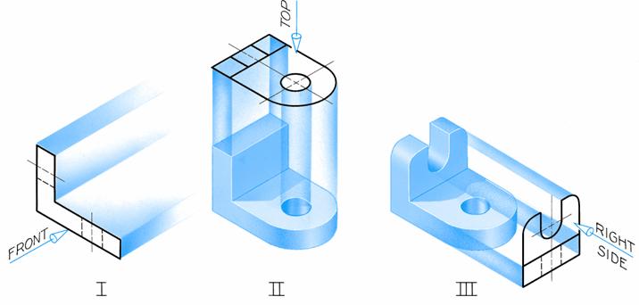
24 Cylindrical Surfaces Example - Machining a Cap (1) A first stage of machining a cap is shown. In stage 1, the removal of the two upper corners forms cylindrical surface A which appears in the top view as surface , in the front view as arc 5, and in the side view as surface 8-9-Y-X.
25 Cylindrical Surfaces Example - Machining a Cap (2) In the second stage, a large reamed hole shows in the front view as circle 16, in the top view as cylindrical surface , and in the side view as cylindrical surface
26 Cylindrical Surfaces Example - Machining a Cap (3) In the third stage, two drilled and counterbored holes are added producing four more cylindrical surfaces and two normal surfaces. The two normal surfaces are those at the bottoms of the counterbores.

27 Cylindrical Surfaces Example - Machining a Cap (4) In the 4 th stage, a cylindrical cut is added, producing two cylindrical surfaces that appear edgewise in the front view as arcs 30 and 33. In the top views, the cylindrical surfaces appear as surfaces , and and in the side view as surfaces and
28 Representation of Holes Blind Drilled Holes A drilled hole is a through hole if it goes through the member. If the hole has a specified depth, the hole is called a blind hole. The depth includes the cylindrical portion of the hole only. The point of the drill leaves a conical bottom in the hole drawn with the 30º-60º triangle.
29 Representation of Holes Through Drilled or Reamed Holes A through drilled or reamed hole is drawn as shown. The note tells how the hole is to be produced. The tolerance is ignored when actually laying out the hole.
30 Representation of Holes Drilled and Counterbored holes A drilled and counterbored hole is a hole that is drilled then the upper part is enlarged cylindrically to a specified diameter and depth. Wrong!
31 Representation of Holes Drilled and Countersunk holes A drilled and countersunk hole is a hole that is drilled then the upper part is enlarged conically to a specified angle and diameter. Wrong!
32 Visualization The ability to visualize or think in three dimensions is one of the most important abilities of successful engineers, and scientists. In practice, this means the ability to study the views of an object and to form a mental picture of it, i.e. to visualize its three dimensional shape To the designer it means the ability to form, a mental picture before the object even exists and the ability to express this image in terms of views.
33 Visualization
34 Visualization The engineer is the master planner in the construction of new equipment, structures, or processes The ability to visualize and to use the graphics language as a means of communication or recording of mental images is indispensable Even experienced engineers may not be able to look at a multiview drawing and instantly visualize the object It is necessary to study the drawing, to read the lines in a logical way, and to piece together the little things until a clear idea of the whole emerges.
35 Alternate Positioning of Views If three views of a wide, flat object are drawn using the conventional arrangement of views, a large wasted space is left on the paper In such cases, the profile plane may be considered hinged to the horizontal plane instead of the frontal plane This places the side view beside the top view, this results in better spacing & sometimes makes the use of a reduced scale unnecessary


36 Alternate Positioning of Views If three views of a wide, flat object are drawn using the conventional arrangement of views, a large wasted space is left on the paper In such cases, the profile plane may be considered hinged to the horizontal plane instead of the frontal plane This places the side view beside the top view, this results in better spacing & sometimes makes the use of a reduced scale unnecessary
37 Partial Views A view may not need to be complete but may show only what is necessary for the clear description of the object. Such a view is a partial view A break line may be used to limit the view, as shown in (a) and (b). If symmetrical, a half-view may be drawn on one side of the center line (c), or a partial view, broken out may be drawn (d). Do not place a break line where it will coincide with a visible or hidden line
38 Partial Views Occasionally the distinctive features of an object are on opposite sides. In either complete side view there will be a considerable overlapping of shapes. In such cases two side views are often the best solution. The views are partial views and in both, certain visible and invisible lines have been omitted for clarity.
39 Revolution Conventions Regular multiview projection may sometimes become awkward, confusing, or actually misleading In part (a) there are three triangular ribs, three holes equally spaced in the base, and a keyway. Regular projection causes the lower rib to appear in a foreshortened position and the holes do not appear in true relation to the rim. Additionally, the keyway is projected as a confusion of a hidden line. In this case, the revolution convention shown in part (c) is preferable.
40 Revolution Conventions Features are revolved in the front view to lie along the vertical center line, from where it is projected to the correct side view.
41 Removed Views Features are revolved in the front view to lie along the vertical center line, from where it is projected to the correct side view.
42 Removed Views A removed view is a complete or partial view removed to another place on the sheet so that it is no longer in direct projection with any other view A removed view may be used to show some feature of the object more clearly, possibly to a large scale, or to save drawing a complete regular view.
43 Removed Views A viewing-plane line is used to indicate the part being viewed; the arrows at the corners show the direction of sight. The removed view should be labeled VIEW A-A or VIEW B-B and so on, the letters refer to those placed at the corners of the viewingplane line.

44 Intersections and tangencies
45 Fillets and Rounds A rounded interior corner is called a fillet, and a rounded exterior corner is called a round. In cast or forged objects, two intersecting rough surfaces produce a rounded corner. If one or both of these surfaces is machined, the corner becomes sharp. On a drawing, a rounded corner means that both intersecting corners are rough, and a sharp corner means that one or both surfaces has been machined. On working drawings, fillets and rounds are never shaded.
46 Conventional Fillets, Rounds and Runouts A runout is produced when a filleted or rounded corner between two plane surfaces intersects a cylindrical surface. The small curve of intersection is called a runout, and is shown in the drawing to represent this intersection. In the figures below, the radiuses of the runouts differ because of the different shapes of the horizontal intersecting members.
47 Conventional Fillets, Rounds and Runouts A runout results when a rounded web intersects a rounded corner. At (e), the top surface of the web is flat with only slight rounds along the edge, while at (f), the top surface of the web is considerably rounded. When two different sizes of fillets intersect, (g), the direction of the fillet is dictated by the larger fillet.
48 First Angle Projection If the vertical and horizontal planes of projection are considered indefinite in extent and intersecting at 90º with each other, the four dihedral angles produced are the first, second, third and fourth angles as shown. The profile plane intersects these two planes, and may extend into all angles. If the object is placed below the horizontal plane and behind the vertical plane, as in the glass box, the object is said to be in third angle projection. In this case, the observer is always outside, and is looking in, so that for all views, the lines of sight proceed from the eye through the planes of projection, and to the object.


49 First Angle Projection If the object is placed above the horizontal plane, and in front of the vertical plane, the object is in first angle. In this case, the observer always looks through the object and to the planes of projection. In this case, the views are projected from the object into a plane. When the planes are unfolded, the right-side view falls at the left of the front view, and the top view falls below the front view. The only ultimate difference between thirdangle and first-angle projection is in the arrangement of the views. The views themselves are the same in both systems.
50 First Angle Projection The symbols used to specify first angle or third angle projections are those of a truncated cone. The circles are visible when viewed from the smaller diameter side. In the first angle projection, these visible circles are projected towards the large diameter side of the cone, but in the third angle projection they are projected towards the small diameter side, from where they are viewed. In the US and Canada, the first angle projection is the current standard
Multiviews and Auxiliary Views
 Multiviews and Auxiliary Views Multiviews and Auxiliary Views Objectives Explain orthographic and multiview projection. Identifying the six principal views. Apply standard line practices to multiviews
ORTHOGRAPHIC PROJECTION
 ORTHOGRAPHIC PROJECTION C H A P T E R S I X OBJECTIVES 1. Recognize and the symbol for third-angle projection. 2. List the six principal views of projection. 3. Understand which views show depth in a drawing
UNIT 5a STANDARD ORTHOGRAPHIC VIEW DRAWINGS
 UNIT 5a STANDARD ORTHOGRAPHIC VIEW DRAWINGS 5.1 Introduction Orthographic views are 2D images of a 3D object obtained by viewing it from different orthogonal directions. Six principal views are possible
ORTHOGRAPHIC PROJECTIONS. Ms. Sicola
 ORTHOGRAPHIC PROJECTIONS Ms. Sicola Objectives List the six principal views of projection Sketch the top, front and right-side views of an object with normal, inclined, and oblique surfaces Objectives
CLASS views from detail on a grid paper. (use appropriate line types to show features) - Optional views. Turn in for grading on class 6 (06/04)
 - Optional views. Turn in for grading on class 6 (06/04)") CLASS 4 Review: - Projections - Orthographic projections Lab: - 3 views from detail on a grid paper. (use appropriate line types to show features) - Optional views. Turn in for grading on class 6 (06/04)
CLASS 4 Review: - Projections - Orthographic projections Lab: - 3 views from detail on a grid paper. (use appropriate line types to show features) - Optional views. Turn in for grading on class 6 (06/04)
Multi-View Drawing Review
 Multi-View Drawing Review Sacramento City College EDT 300/ENGR 306 EDT 300 / ENGR 306 - Chapter 5 1 Objectives Identify and select the various views of an object. Determine the number of views needed to
Multiview Drawing. Definition: Graphical representation of a 3- dimensional object on one plane (sheet of paper) using two or more views.
 using two or more views.") Multiview Drawing Definition: Graphical representation of a 3- dimensional object on one plane (sheet of paper) using two or more views. Multiview Drawing Another name for multiview drawing is orthographic
Multiview Drawing Definition: Graphical representation of a 3- dimensional object on one plane (sheet of paper) using two or more views. Multiview Drawing Another name for multiview drawing is orthographic
GL5: Visualisation and reading drawings
 436-105 Engineering Communications GL5:1 GL5: Visualisation and reading drawings Being able to both: represent a 3D object in multiview drawings interpret a multiview drawing to visualise a 3D object is
Technological Design Mr. Wadowski. Orthographic & Isometric Drawing Lesson
 Technological Design Mr. Wadowski Orthographic & Isometric Drawing Lesson TOPICS Working Drawings, Isometric Drawings & Orthographic Drawings Glass box concept Multiview projection Orthographic projection
Multiview Projection
 DFTG-1305 Technical Drafting Prof. Francis Ha Session 4 Multiview Projection (or Orthographic Projection) Reading: Geisecke s textbook: 14 th Ed. Chapter 5 p.162 15 th Ed. Chapter 6 p.232 Update: 17-0510
ENGINEERING GRAPHICS ESSENTIALS
 ENGINEERING GRAPHICS ESSENTIALS Text and Digital Learning KIRSTIE PLANTENBERG FIFTH EDITION SDC P U B L I C AT I O N S Better Textbooks. Lower Prices. www.sdcpublications.com ACCESS CODE UNIQUE CODE INSIDE
Copyrighted Material. Copyrighted Material. Copyrighted. Copyrighted. Material
 Engineering Graphics ORTHOGRAPHIC PROJECTION People who work with drawings develop the ability to look at lines on paper or on a computer screen and "see" the shapes of the objects the lines represent.
AUXILIARY VIEWS C H A P T E R N I N E
 AUXILIARY VIEWS C H A P T E R N I N E Giesecke, Hill, Spencer, Dygdon, Novak, Lockhart, Goodman 1 OBJECTIVES 1. Create an auxiliary view from orthographic views. 2. Draw folding lines or reference-plane
11/12/2015 CHAPTER 7. Axonometric Drawings (cont.) Axonometric Drawings (cont.) Isometric Projections (cont.) 1) Axonometric Drawings
 Axonometric Drawings (cont.) Isometric Projections (cont.) 1) Axonometric Drawings") CHAPTER 7 1) Axonometric Drawings 1) Introduction Isometric & Oblique Projection Axonometric projection is a parallel projection technique used to create a pictorial drawing of an object by rotating the
CHAPTER 7 1) Axonometric Drawings 1) Introduction Isometric & Oblique Projection Axonometric projection is a parallel projection technique used to create a pictorial drawing of an object by rotating the
Engineering Graphics, Class 13 Descriptive Geometry. Mohammad I. Kilani. Mechanical Engineering Department University of Jordan
 Engineering Graphics, Class 13 Descriptive Geometry Mohammad I. Kilani Mechanical Engineering Department University of Jordan Projecting a line into other views Given the front and right side projections
DFTG-1305 Technical Drafting Prof. Francis Ha
 DFTG-1305 Technical Drafting Prof. Francis Ha Session 4 Orthographic Projection (or Multiview Projection) Reading: Geisecke s textbook: 14 th Ed. Chapter 5 p.162 15 th Ed. Chapter 6 p.232 Update: 18-0205
Chapter 2: Dimensioning Basic Topics Advanced Topics Exercises
 Chapter 2: Dimensioning Basic Topics Advanced Topics Exercises Dimensioning: Basic Topics Summary 2-1) Detailed Drawings 2-2) Learning to Dimension 2-3) Dimension Appearance and Techniques. 2-4) Dimensioning
Orthographic Projection 1
 Orthographic Projection 1 What Is Orthographic Projection? Basically it is a way a representing a 3D object on a piece of paper. This means we make the object becomes 2D. The difference between Orthographic
Engineering Graphics Essentials with AutoCAD 2015 Instruction
 Kirstie Plantenberg Engineering Graphics Essentials with AutoCAD 2015 Instruction Text and Video Instruction Multimedia Disc SDC P U B L I C AT I O N S Better Textbooks. Lower Prices. www.sdcpublications.com
ENGINEERING GRAPHICS ESSENTIALS
 ENGINEERING GRAPHICS ESSENTIALS with AutoCAD 2012 Instruction Introduction to AutoCAD Engineering Graphics Principles Hand Sketching Text and Independent Learning CD Independent Learning CD: A Comprehensive
DMT113 Engineering Drawing. Chapter 3 Stretch System
 DMT113 Engineering Drawing Chapter 3 Stretch System Contents Theory & Multiview Planes 6 Principle Views Multiview Sketching Technique & Perspective First & Third Angle Multiview Representations Theory
Engineering Drawing Lecture 5 PROJECTION THEORY
 University of Palestine College of Engineering & Urban Planning First Level Engineering Drawing Lecture 5 PROJECTION THEORY Lecturer: Eng. Eman Al.Swaity Eng.Heba hamad PART 1 PROJECTION METHOD TOPICS
ENGINEERING DRAWING. UNIT III - Part A
 DEVELOPMENT OF SURFACES: ENGINEERING DRAWING UNIT III - Part A 1. What is meant by development of surfaces? 2. Development of surfaces of an object is also known as flat pattern of the object. (True/ False)
ME1105 Engineering Drawing & Design
 City University London Term 1 Assessment 2008/2009 School of Engineering and Mathematical Sciences ME1105 Engineering Drawing & Design Student Name:.., Group: Examination duration: Reading time: This paper
Orthographic Projection
 Orthographic Projection Why Orthographic Projection is used in technical drawing Orthographic projection is a method of producing a number of separate two-dimensional inter-related views, which are mutually
Mechanical Drawing. Unit 2 Study Guide for Chapters 6-10
 Mechanical Drawing Unit 2 Study Guide for Chapters 6-10 Chapter 6 Multiview Drawing Section 6.1 Understanding Orthographic Projection A. Technical Drawing: How can a technical drawing give more accurate
At the conclusion of this unit you should be able to accomplish the following with a 70% accuracy
 7 Multiview Drawing OBJECTIVES At the conclusion of this unit you should be able to accomplish the following with a 70% accuracy 1. explain the importance of mulitview drawing as a communication tool far
Student Name: Teacher: Date: District: Rowan. Assessment: 9_12 T and I IC61 - Drafting I Test 1. Description: Unit C - Sketching - Test 2.
 Student Name: Teacher: Date: District: Rowan Assessment: 9_12 T and I IC61 - Drafting I Test 1 Description: Unit C - Sketching - Test 2 Form: 501 1. The most often used combination of views includes the:
Dimensioning. Dimensions: Are required on detail drawings. Provide the shape, size and location description: ASME Dimensioning Standards
 Dimensioning Dimensions: Are required on detail drawings. Provide the shape, size and location description: - Size dimensions - Location dimensions - Notes Local notes (specific notes) General notes ASME
Add labels to the sides...
 Orthographic Drawings Orthographic Projection A projection on a plane, using lines perpendicular to the plane Graphic communications has many forms. Orthographics is one such form. It was developed as
PROJECTIONS PARALLEL CONICAL PROJECTIONS PROJECTIONS OBLIQUE ORTHOGRAPHIC PROJECTIONS PROJECTIONS
 PROJECTIONS CONICAL PROJECTIONS PARALLEL PROJECTIONS OBLIQUE PROJECTIONS ORTHOGRAPHIC PROJECTIONS ISOMETRIC MULTI-VIEW an object; The Description of Forms Behind every drawing of an object is space relationship
ENGINEERING GRAPHICS ESSENTIALS. (A Text and Lecture Aid) Second Edition. Kirstie Plantenberg University of Detroit Mercy SDC PUBLICATIONS
 Second Edition. Kirstie Plantenberg University of Detroit Mercy SDC PUBLICATIONS") ENGINEERING GRAPHICS ESSENTIALS (A Text and Lecture Aid) Second Edition Kirstie Plantenberg University of Detroit Mercy SDC PUBLICATIONS Schroff Development Corporation www.schroff.com www.schroff-europe.com
ENGINEERING GRAPHICS ESSENTIALS (A Text and Lecture Aid) Second Edition Kirstie Plantenberg University of Detroit Mercy SDC PUBLICATIONS Schroff Development Corporation www.schroff.com www.schroff-europe.com
ME 111: Engineering Drawing
 ME 111: Engineering Drawing Lecture 5 12-08-2011 Orthographic projection and Projection of Points Indian Institute of Technology Guwahati Guwahati 781039 1 Orthographic Projection A parallel projection
2009 Academic Challenge
 2009 Academic Challenge ENGINEERING GRAPHICS TEST SECTIONAL This Test Consists of 50 Questions Engineering Graphics Test Production Team Ryan Brown, Illinois State University Author/Team Leader Kevin Devine,
Auxiliary view KCEC1101
 Auxiliary view KCEC1101 Introduction There are times when one of the six principal views will not completely describe an object. This is especially true when there are inclined or oblique planes or features
7/9/2009. Offset Tool. Offset Tool. Offsetting - Erasing the Original Object. Chapter 8 Construction Tools and Multiview Drawings
 Chapter 8 Construction Tools and Multiview Drawings Use the OFFSET tool to draw parallel lines and curves. Mark points on objects at equal lengths using the DIVIDE tool. Set designated increments on an
ORTHOGRAPHIC PROJECTION
 ORTHOGRAPHIC PROJECTION INTRODUCTION Any object has three dimensions, that is, length, width and thickness. A projection is defined as a representation of an object on a two dimensional plane. The projections
ME 113 Computer Aided Engineering Drawing
 ME 113 Computer Aided Engineering Drawing Orthographic Projection - Visualizing Solids and Multiview Drawings Asst.Prof.Dr.Turgut AKYÜREK Çankaya University, Ankara Visualizing Solids and Multiview Drawings
AutoCAD Tutor 2011 Support Docs
 AutoCAD Tutor 2011 Support Docs CHAPTER 1 CUSTOMIZING THE QUICK ACCESS TOOLBAR One of the advantages of the Quick Access Toolbar is the ability to display the AutoCAD commands that you frequently use.
A Concise Introduction to Engineering Graphics
 A Concise Introduction to Engineering Graphics Fourth Edition Including Worksheet Series A Timothy J. Sexton, Professor Department of Industrial Technology Ohio University BONUS Book on CD: TECHNICAL GRAPHICS
Chapter 5 SECTIONS OF SOLIDS 5.1 INTRODUCTION
 Chapter 5 SECTIONS OF SOLIDS 5.1 INTRODUCTION We have studied about the orthographic projections in which a 3 dimensional object is detailed in 2-dimension. These objects are simple. In engineering most
GE 6152 ENGINEERING GRAPHICS
 GE 6152 ENGINEERING GRAPHICS UNIT - 4 DEVELOPMENT OF SURFACES Development of lateral surfaces of simple and truncated solids prisms, pyramids, cylinders and cones - Development of lateral surfaces of solids
2010 Academic Challenge
 2010 Academic Challenge ENGINEERING GRAPHICS TEST STATE FINALS This Test Consists of 40 Questions Engineering Graphics Test Production Team Ryan K. Brown, Illinois State University Author/Team Leader Jacob
Contents. Notes on the use of this publication
 Contents Preface xxiii Scope Notes on the use of this publication xxv xxvi 1 Layout of drawings 1 1.1 General 1 1.2 Drawing sheets 1 1.3 Title block 2 1.4 Borders and frames 2 1.5 Drawing formats 2 1.6
Chapter 4 ORTHOGRAPHIC PROJECTION
 Chapter 4 ORTHOGRAPHIC PROJECTION 4.1 INTRODUCTION We, the human beings are gifted with power to think. The thoughts are to be shared. You will appreciate that different ways and means are available to
CE 100 Civil Engineering Drawing Sessional (Lab Manual)
") CE 100 Civil Engineering Drawing Sessional (Lab Manual) Department of Civil Engineering Ahsanullah University of Science and Technology November, 2017 1 Preface This course is designed to provide civil
CE 100 Civil Engineering Drawing Sessional (Lab Manual) Department of Civil Engineering Ahsanullah University of Science and Technology November, 2017 1 Preface This course is designed to provide civil
Guide To British Standards
 Guide To British Standards Higher Graphic Communication C O N T E N T S page TITLE BLOCK 2 DRAWING SCALES 2 LINE TYPES 3 ORTHOGRAPHIC PROJECTION 4 SECTIONAL VIEWS 4 SCREW THREADS & COMPONENTS 7 INTERUPTTED
Civil Engineering Drawing
 Civil Engineering Drawing Third Angle Projection In third angle projection, front view is always drawn at the bottom, top view just above the front view, and end view, is drawn on that side of the front
ENGINEERING DRAWING. 1. Set squares are used to draw different angles. What is the angel a formed by the 45⁰ set square? Give a brief answer.
 ENGINEERING DRAWING 1. Set squares are used to draw different angles. What is the angel a formed by the 45⁰ set square? Give a brief answer. 2. Which is the correct method of hatching a plane surface?
Geometric dimensioning & tolerancing (Part 1) KCEC 1101
 KCEC 1101") Geometric dimensioning & tolerancing (Part 1) KCEC 1101 Introduction Before an object can be built, complete information about both the size and shape of the object must be available. The exact shape of
Geometric dimensioning & tolerancing (Part 1) KCEC 1101 Introduction Before an object can be built, complete information about both the size and shape of the object must be available. The exact shape of
2004 Academic Challenge
 2004 Academic Challenge ENGINEERING GRAPHICS TEST - REGIONAL Engineering Graphics Test Production Team Ryan Brown, Illinois State University Author/Team Coordinator Kevin Devine, Illinois State University
DELHI TECHNOLOGICAL UNIVERSITY ENGINEERING GRAPHICS LAB MANUAL
 DELHI TECHNOLOGICAL UNIVERSITY ENGINEERING GRAPHICS LAB MANUAL NAME: - ROLL NO: - GROUP: - BRANCH: - GROUP TEACHER: Page 1 www.rooplalrana.com 1 GENERAL INSTRUCTIONS FOR ENGG. GRAPHICS LAB 1) Students
SDC PUBLICATIONS. Schroff Development Corporation
 SDC PUBLICATIONS Schroff Development Corporation www.schroff.com www.schroff-europe.com SECTIONING In chapter 3 you will learn how to create various types of sectional views. Sectional views allow you
ENGINEERING GRAPHICS UNIT V ISOMETRIC PROJECTION PERSPECTIVE PROJECTION
 ENGINEERING GRAPHICS UNIT V ISOMETRIC PROJECTION PERSPECTIVE PROJECTION 1.PICTORIAL PROJECTIONS To visualize the shape of the whole object in its 3- D form, all the two or three orthographic views of the
Mechanical Engineering Drawing
 Mechanical Engineering Drawing MECH 211 LECTURE 3 Contents of the lecture Shape description Shape generation Sectional views Auxiliary views Shape description Geometric shapes are seen according to view
MULTIPLE CHOICE QUESTIONS - CHAPTER 6
 MULTIPLE CHOICE QUESTIONS - CHAPTER 6 1. The selection of the front view in executing a multiview drawing of an object is dependent upon the following factors: a. size and shape of the object and their
Geometric Dimensioning and Tolerancing
 Geometric Dimensioning and Tolerancing (Known as GDT) What is GDT Helps ensure interchangeability of parts. Use is dictated by function and relationship of the part feature. It does not take the place
CHAPTER 01 PRESENTATION OF TECHNICAL DRAWING. Prepared by: Sio Sreymean
 CHAPTER 01 PRESENTATION OF TECHNICAL DRAWING Prepared by: Sio Sreymean 2015-2016 Why do we need to study this subject? Effectiveness of Graphics Language 1. Try to write a description of this object. 2.
GOVERNMENT POLYTECHNIC, VALSAD MECHANICAL ENGINEERING DEPARTMENT ASSIGNMENT SUB: MECHANICAL DRAFTING (C321901) TERM:172
 TERM:172") GOVERNMENT POLYTECHNIC, VALSAD MECHANICAL ENGINEERING DEPARTMENT ASSIGNMENT SUB: MECHANICAL DRAFTING (C321901) TERM:172 1) When all the dimension are placed above the dimension line, it is called (a) Aligned
GOVERNMENT POLYTECHNIC, VALSAD MECHANICAL ENGINEERING DEPARTMENT ASSIGNMENT SUB: MECHANICAL DRAFTING (C321901) TERM:172 1) When all the dimension are placed above the dimension line, it is called (a) Aligned
Beginning Engineering Graphics 3 rd Week Lecture Notes Instructor: Edward N. Locke Topic: The Coordinate System, Types of Drawings and Orthographic
 Beginning Engineering Graphics 3 rd Week Lecture Notes Instructor: Edward N. Locke Topic: The Coordinate System, Types of Drawings and Orthographic 1 st Subject: The Cartesian Coordinate System The Cartesian
Module 1H: Creating an Ellipse-Based Cylindrical Sheet-metal Lateral Piece
 Inventor (10) Module 1H: 1H- 1 Module 1H: Creating an Ellipse-Based Cylindrical Sheet-metal Lateral Piece In this Module, we will learn how to create an ellipse-based cylindrical sheetmetal lateral piece
Question. Question. Product Features The Vocabulary of Design Download from web site. CAD/Fab Orthographic Projection 4
 Orthographic Projection Question What is the name of the feature indicated? A. Countersink B. Counterbore C. Spotface D. Hole E. Stepped hole CAD/Fab Assemblies & Mobility 2 Question Product Features The
Drawing sheet: - The various size of the drawing sheet used for engineering drawing as per IS Are listed in the table
 Dronacharya Group of Institutions, Greater Noida Computer Aided Engineering Graphics (CAEG) (NCE 151/251) List of Drawing Sheets: 1. Letter writing & Dimensioning. 2. Projection of Points & Lines. 3. Projection
2003 Academic Challenge
 Worldwide Youth in Science and Engineering 2003 Academic Challenge ENGINEERING GRAPHICS TEST - SECTIONAL Engineering Graphics Test Production Team Ryan Brown, Illinois State University Author/Team Coordinator
2003 Academic Challenge
 Worldwide Youth in Science and Engineering 2003 Academic Challenge ENGINEERING GRAPHICS TEST - REGIONAL Engineering Graphics Test Production Team Ryan Brown, Illinois State University Author/Team Coordinator
Trade of Metal Fabrication. Module 6: Fabrication Drawing Unit 13: Parallel Line Development Phase 2
 Trade of Metal Fabrication Module 6: Fabrication Drawing Unit 13: Parallel Line Development Phase 2 Table of Contents List of Figures... 4 List of Tables... 5 Document Release History... 6 Module 6 Fabrication
Shaft Hanger - SolidWorks
 ME-430 INTRODUCTION TO COMPUTER AIDED DESIGN Shaft Hanger - SolidWorks BY: DR. HERLI SURJANHATA ASSIGNMENT Submit TWO isometric views of the Shaft Hanger with your report, 1. Shaded view of the trimetric
2007 Academic Challenge
 2007 Academic Challenge ENGINEERING GRAPHICS TEST - STATE FINALS This Test Consists of 50 Questions Engineering Graphics Test Production Team Ryan Brown, Illinois State University Author/Team Coordinator
DFTG-1305 Technical Drafting Prof. Francis Ha
 DFTG-1305 Technical Drafting Prof. Francis Ha Session 5 Dimensioning Geisecke s textbook: 14 th Ed. Chapter 10 p. 362 15 th Ed. Chapter 11 p. 502 Update: 17-0508 Dimensioning Part 1 of 2 Dimensioning Summary
UNIT I PLANE CURVES AND FREE HAND SKETCHING CONIC SECTIONS
 UNIT I PLANE CURVES AND FREE HAND SKETCHING CONIC SECTIONS Definition: The sections obtained by the intersection of a right circular cone by a cutting plane in different positions are called conic sections
Set No - 1 I B. Tech I Semester Regular/Supplementary Examinations Jan./Feb ENGINEERING DRAWING (EEE)
") Set No - 1 I B. Tech I Semester Regular/Supplementary Examinations Jan./Feb. - 2015 ENGINEERING DRAWING Time: 3 hours (EEE) Question Paper Consists of Part-A and Part-B Answering the question in Part-A
Set No - 1 I B. Tech I Semester Regular/Supplementary Examinations Jan./Feb. - 2015 ENGINEERING DRAWING Time: 3 hours (EEE) Question Paper Consists of Part-A and Part-B Answering the question in Part-A
SolidWorks 95 User s Guide
 SolidWorks 95 User s Guide Disclaimer: The following User Guide was extracted from SolidWorks 95 Help files and was not originally distributed in this format. All content 1995, SolidWorks Corporation Contents
Bridge Course On Engineering Drawing for Mechanical Engineers
 G. PULLAIAH COLLEGE OF ENGINEERING AND TECHNOLOGY Accredited by NAAC with A Grade of UGC, Approved by AICTE, New Delhi Permanently Affiliated to JNTUA, Ananthapuramu (Recognized by UGC under 2(f) and 12(B)
Study Unit. Auxiliary Views. This sneak preview of your study material has been prepared in advance of the book's actual online release.
 Study Unit Auxiliary Views This sneak preview of your study material has been prepared in advance of the book's actual online release. iii Preview You re entering now into another subject area in your
Graphical Communication
 Chapter 9 Graphical Communication mmm Becoming a fully competent engineer is a long yet rewarding process that requires the acquisition of many diverse skills and a wide body of knowledge. Learning most
Design & Communication Graphics Higher Level Sections B and C (180 marks)
") Coimisiún na Scrúduithe Stáit State Examinations Commission 2016. M81BC Leaving Certificate Examination, 2016 Design & Communication Graphics Higher Level Sections B and C (180 marks) Wednesday, 22 June
Coimisiún na Scrúduithe Stáit State Examinations Commission 2016. M81BC Leaving Certificate Examination, 2016 Design & Communication Graphics Higher Level Sections B and C (180 marks) Wednesday, 22 June
ENGINEERING GRAPHICS 1E9
 Lecture 3 Monday, 15 December 2014 1 ENGINEERING GRAPHICS 1E9 Lecture 3: Isometric Projections Lecture 3 Monday, 15 December 2014 2 What is ISOMETRIC? It is a method of producing pictorial view of an object
Technical Graphics Higher Level
 Coimisiún na Scrúduithe Stáit State Examinations Commission Junior Certificate Examination 2005 Technical Graphics Higher Level Marking Scheme Sections A and B Section A Q1. 12 Four diagrams, 3 marks for
APJ ABDUL KALAM TECHNOLOGICAL UNIVERSITY SECOND SEMESTER B.TECH DEGREE EXAMINATION, MAY PART A Answer ANY Two questions. 10 marks each.
 B B2B111 Pages: 2 Reg. No. Name: SECOND SEMESTER B.TECH DEGREE EXAMINATION, MAY 2017 Max.Marks:50 Course Code: BE110 Duration:3Hours Answer ANY Two questions. 10 marks each. 1. A line AB 100 mm long and
ME 114 Engineering Drawing II
 ME 114 Engineering Drawing II FITS, TOLERANCES and SURFACE QUALITY MARKS Mechanical Engineering University of Gaziantep Dr. A. Tolga Bozdana Assistant Professor Tolerancing Tolerances are used to control
A Concise Introduction to Engineering Graphics
 Concise Introduction to Engineering Graphics ourth Edition Including Worksheet Series imothy J. Sexton, Professor Department of Industrial echnology Ohio University ONUS ook on CD: ECHNICL GRPHICS Meyers,
Philadelphia University Faculty of Engineering Mechanical Engineering Department
 Philadelphia University Faculty of Engineering Mechanical Engineering Department Basics of Engineering Drawing Manual Done by:- Eng. Laith R.I. Batarseh Eng. Hanan Khamis 2017 1 Table of contents SUBJECT
ISOMETRIC PROJECTION. Contents. Isometric Scale. Construction of Isometric Scale. Methods to draw isometric projections/isometric views
 ISOMETRIC PROJECTION Contents Introduction Principle of Isometric Projection Isometric Scale Construction of Isometric Scale Isometric View (Isometric Drawings) Methods to draw isometric projections/isometric
MODELING AND DESIGN C H A P T E R F O U R
 MODELING AND DESIGN C H A P T E R F O U R OBJECTIVES 1. Identify and specify basic geometric elements and primitive shapes. 2. Select a 2D profile that best describes the shape of an object. 3. Identify
Engineering Working Drawings Basics
 Engineering Working Drawings Basics Engineering graphics is an effective way of communicating technical ideas and it is an essential tool in engineering design where most of the design process is graphically
Introduction to Autodesk Inventor User Interface Student Manual MODEL WINDOW
 Emmett Wemp EDTECH 503 Introduction to Autodesk Inventor User Interface Fill in the blanks of the different tools available in the user interface of Autodesk Inventor as your instructor discusses them.
JUNIOR CERTIFICATE 2009 MARKING SCHEME TECHNICAL GRAPHICS HIGHER LEVEL
 . JUNIOR CERTIFICATE 2009 MARKING SCHEME TECHNICAL GRAPHICS HIGHER LEVEL Sections A and B Section A any ten questions from this section Q1 12 Four diagrams, 3 marks for each correct label. Q2 12 2 marks
ENGINEERING DRAWING LECTURE 4
 ENGINEERING DRAWING LECTURE 4 Conventions Convention or Code: The representation of any matter by some sign or mark on the drawing is known as convention or code. The convention make the drawing simple
Chapter 5 Pictorial sketching
 Chapter 5 Pictorial sketching Contents Freehand sketching techniques Pictorial projections - Axonometric - Oblique Isometric projection vs isometric sketch Isometric sketch from an orthographic views Isometric
1. Open the Feature Modeling demo part file on the EEIC website. Ask student about which constraints needed to Fully Define.
 BLUE boxed notes are intended as aids to the lecturer RED boxed notes are comments that the lecturer could make Control + Click HERE to view enlarged IMAGE and Construction Strategy he following set of
Lecture 6 ( ): Theory of Multi-view Orthographic Projections
: Theory of Multi-view Orthographic Projections") Lecture 6 (06.08.12): Theory of Multi-view Orthographic Projections Dr. Sharad Gokhale Civil Engineering Department, IIT Guwahati 208, M-Block, Academic Complex Email: sharadbg@iitg.ernet.in Telephone
Lecture 6 (06.08.12): Theory of Multi-view Orthographic Projections Dr. Sharad Gokhale Civil Engineering Department, IIT Guwahati 208, M-Block, Academic Complex Email: sharadbg@iitg.ernet.in Telephone
Dimensioning 2-4) Dimensioning and Locating Simple Features
 Dimensioning and Locating Simple Features") Dimensioning 2-4) Dimensioning and Locating Simple Features Dimensioning Features a) A circle is dimensioned by its diameter and an arc by its radius using a leader line and a note. Exercise 2-6 Circular
Dimensioning 2-4) Dimensioning and Locating Simple Features Dimensioning Features a) A circle is dimensioned by its diameter and an arc by its radius using a leader line and a note. Exercise 2-6 Circular
2013 Academic Challenge
 2013 Academic Challenge ENGINEERING GRAPHICS TEST STATE FINALS This Test Consists of 40 Questions Engineering Graphics Test Production Team Ryan Brown, Illinois State University Author/Team Leader Jacob
Module 1G: Creating a Circle-Based Cylindrical Sheet-metal Lateral Piece with an Overlaying Lateral Edge Seam And Dove-Tail Seams on the Top Edge
 Inventor (10) Module 1G: 1G- 1 Module 1G: Creating a Circle-Based Cylindrical Sheet-metal Lateral Piece with an Overlaying Lateral Edge Seam And Dove-Tail Seams on the Top Edge In Module 1A, we have explored
DIMENSIONING ENGINEERING DRAWINGS
 DIMENSIONING ENGINEERING DRAWINGS An engineering drawing must be properly dimensioned in order to convey the designer s intent to the end user. Dimensions provide the information needed to specify the
Isometric Drawing Chapter 26
 Isometric Drawing Chapter 26 Sacramento City College EDT 310 EDT 310 - Chapter 26 - Isometric Drawing 1 Drawing Types Pictorial Drawing types: Perspective Orthographic Isometric Oblique Pictorial - like
C H A P T E R E L E V E N
 DIMENSIONING C H A P T E R E L E V E N Giesecke, Hill, Spencer, Dygdon, Novak, Lockhart, Goodman 1 OBJECTIVES 1. Use conventional dimensioning techniques to describe size and shape accurately on an engineering
C A R I B B E A N E X A M I N A T I O N S C O U N C I L REPORT ON CANDIDATES WORK IN THE SECONDARY EDUCATION CERTIFICATE EXAMINATION MAY/JUNE 2010
 C A R I B B E A N E X A M I N A T I O N S C O U N C I L REPORT ON CANDIDATES WORK IN THE SECONDARY EDUCATION CERTIFICATE EXAMINATION MAY/JUNE 2010 TECHNICAL DRAWING GENERAL PROFICIENCY Copyright 2010 Caribbean
Continuous thick. Continuous thin. Continuous thin straight with zigzags. Dashed thin line. Chain thin. Chain thin double dash
 Types of line used Continuous thick Used for visible outlines and edges. Continuous thin Used for projection, dimensioning, leader lines, hatching and short centre lines. Continuous thin straight with