ENGINEERING GRAPHICS ESSENTIALS
|
|
|
- Everett Griffin
- 5 years ago
- Views:
Transcription


1 ENGINEERING GRAPHICS ESSENTIALS Text and Digital Learning KIRSTIE PLANTENBERG FIFTH EDITION SDC P U B L I C AT I O N S Better Textbooks. Lower Prices. ACCESS CODE UNIQUE CODE INSIDE

 Visit")


2 Powered by TCPDF ( Visit the following websites to learn more about this book:
3 CHAPTER 2 ORTHOGRAPHIC PROJECTIONS CHAPTER OUTLINE 2.1) ORTHOGRAPHIC PROJECTION INTRODUCTION ) The Six Principle Views ) THE GLASS BOX METHOD ) THE STANDARD VIEWS ) The Front View ) LINE TYPES USED IN AN ORTHOGRAPHIC PROJECTION ) RULES FOR LINE CREATION AND USE ) Hidden Lines ) Center Lines ) Phantom Lines ) Break Lines ) Line Type Precedence ) CREATING AN ORTHOGRAPHIC PROJECTION ) Projection Symbol ) APPLYING WHAT WE HAVE LEARNED ORTHOGRAPHIC PROJECTIONS QUESTIONS ORTHOGRAPHIC PROJECTIONS PROBLEMS
4 CHAPTER SUMMARY In this chapter you will learn how to create orthographic projections. An orthographic projection describes the shape of an object. It is a two-dimensional representation of a threedimensional object. Different line types are used to indicate visible features, hidden features and symmetry. By the end of this chapter, you will be able to create a technically correct orthographic projection and visualize its three-dimensional form. 2.1) ORTHOGRAPHIC PROJECTION INTRODUCTION An orthographic projection enables us to represent a three-dimensional object in two dimensions (see Figure 2.1-1). An orthographic projection is a drawing that shows different sides of an object on a sheet of paper (i.e. in two dimensions). The drawing is formed by projecting the edges of the object onto a projection plane from different viewing perspectives. Orthographic projections allow us to represent the shape of an object usually using three views; however, a part may be represented completely with only one or two views. These views together with dimensions and notes are sufficient to manufacture the part. Figure 2.1-1: Orthographic projection ) The Six Principle Views The six principle viewing directions of an orthographic projection and their associated view names are shown in Figure These viewing directions are used to create the six principle views. Each principle view is created by looking at the object in the directions indicated in Figure and drawing what is seen, as well as, what is hidden from view. 2-2
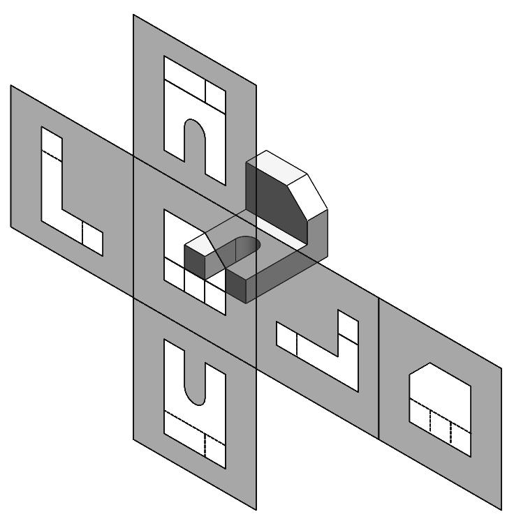
5 Figure 2.1-2: The six principle viewing directions 2.2) THE GLASS BOX METHOD The glass box method is a very convenient way of visualizing how an orthographic projection is created. To obtain an orthographic projection, an object is placed in an imaginary glass box as shown in Figure The sides of the glass box represent the six principle planes. Images of the object are projected onto the sides of the box to create the six principle views. The box is then unfolded to lie flat, showing all views in a twodimensional plane. Figure shows the glass box being unfolded to create the orthographic projection of the object. 2-3

6 Figure 2.2-1: Object in a glass box 2-4


7 Figure 2.2-2: Glass box being unfolded 2-5
8 Exercise 2.2-1: Principle views Label the five remaining principle views with the appropriate view name. Figure indicates the six principle viewing directions as well as their associated view names. What are the differences between the Right Side and Left Side views? What are the differences between the Top and Bottom, and Front and Rear views? Which view(s) have the least number of hidden or dashed lines? 2-6
9 2.3) THE STANDARD VIEWS When constructing an orthographic projection, we need to include enough views to completely describe the true shape of the part. The more complex a part, the more views are needed to completely describe its shape. Most objects require three views to be completely described. The standard views used in an orthographic projection are the front, top, and right side views. The other views (bottom, rear, left side) are omitted since they usually do not add any new information. The top, front, and bottom views are all aligned vertically and share the same width dimension. The left side, front, right side, and rear views are all aligned horizontally and share the same height dimension. It is not always necessary to use the three standard views. Some objects can be completely described in one or two views. For example, a sphere only requires one view, and a block only requires two views. No matter how many views are used, the viewing directions should be chosen to minimize the use of hidden lines and convey maximum clarity ) The Front View The front view shows the most features or characteristics of the object. It usually contains the least number of hidden lines. The exception to this rule is when the object has a predefined or generally accepted front view. All other views are based on the orientation chosen for the front view. 2.4) LINE TYPES USED IN AN ORTHOGRAPHIC PROJECTION Line type and line weight provide valuable information to the print reader. For example, the type and weight of a line can answer the following questions: Is the feature visible or hidden from view? Is the line part of the object or part of a dimension? Is the line indicating symmetry? There are four commonly used line types: continuous, hidden, center and phantom. Important lines are thicker than less important thin lines. The following is a list of common line types and widths used in a basic orthographic projection that has no section views or dimensions. 1. Visible lines: Visible lines represent visible edges and boundaries. The line type is continuous and the line weight is thick. 2. Hidden lines: Hidden lines represent edges and boundaries that cannot be seen. The line type is dashed and the line weight is medium thick. 3. Center lines: Center lines represent axes, center points, planes of symmetry, circle of centers, and paths of motion. A circle of centers is usually a hole pattern that exists on the circumference of a circle. A path of motion indicates the path a feature takes when moving from one position to the next. The line type is long dash short dash and the line weight is thin. 4. Phantom lines: Phantom lines are used to indicate imaginary features. For example, they are used to indicate the alternate positions of moving parts, adjacent positions of related parts, repeated detail, reference planes between adjacent views, and filleted and rounded corners. The line type is long dash short dash short dash and the line weight is usually thin. 5. Break lines: Break lines are used to show imaginary breaks in objects. A break line is usually made up of a series of connecting arcs. The line type is continuous and the line weight is usually thick. 2-7
10 Exercise 2.4-1: Line types Using the line type definitions, match each line type name with the appropriate line type. Visible Line Hidden Line Center Line Phantom Line Dimension and Extension Lines Cutting Plane Line Section Lines Break Line 2-8
11 Exercise 2.4-2: Line identification In the following orthographic projection, identify the line type of each line that is pointed to. Then, identify the associated feature (using a letter) of the selected lines. Line width and type are controlled by the ASME Y14.2 standard. The standard recommends using, no less than, two line widths. Important lines should be twice as thick as the less important thin lines. Thick lines should be at least 0.6 mm in width and thin lines should be at least 0.3 mm in width. However, to further distinguish line importance, it is recommended to use four different thicknesses or weights: thin, medium, thick, and very thick. The actual line thickness should be chosen such that there is a visible difference between the line weights; however, they should not be too thick or thin making it difficult to read the print. The thickness of the lines should be adjusted according to the size and complexity of the part. Table contains a list of common line types and widths used in an orthographic projection. 2-9
12 Line type name Line type Use Thickness Visible visible edges mm Hidden hidden edges mm Center symmetry, circle 0.3 mm of centers, paths of motion Phantom imaginary features 0.3 mm Break imaginary brakes in the part mm Table 2.4-1: Common line types and their thicknesses 2.5) RULES FOR LINE CREATION AND USE The rules and guide lines for line creation should be followed in order to create lines that are effective in communicating the drawing information. However, due to computer automation, some of the rules may be hard to follow. The rules of line creation and use are in accordance with the ASME Y14.2 and ASME Y14.3 standards ) Hidden Lines Hidden lines represent edges and boundaries that cannot be seen. Rule 1. The length of the hidden line dashes may vary slightly as the size of the drawing changes. For example, a very small part may require smaller dashes in order for the hidden line to be recognized. Rule 2. Hidden lines should always begin and end with a dash, except when the hidden line begins or ends at a parallel visible line (see Figure 2.5-1). Rule 3. Hidden line dashes should join at corners (see Figure 2.5-2). Figure 2.5-1: Drawing hidden lines 2-10
13 Figure 2.5-2: Hidden lines at corner 2.5.2) Center Lines Center lines are used to identify planes and axes of symmetry and are important for interpreting cylindrical shapes as shown in Figure If a center line is used to indicate part symmetry, two short thick parallel lines are placed on the center line, outside the part, and perpendicular to the center line (see Figure 2.5-4). Center lines are also used to indicate circle of centers and paths of motion as shown in Figure Short center lines may be left unbroken if it is certain that they won t be confused with another line type. However, every measure should be taken to produce a break. Rule 1. Center lines should start and end with long dashes (see Figure 2.5-3). Rule 2. Center lines should intersect by crossing either the long dashes or the short dashes (see Figure 2.5-6). Rule 3. Center lines should extend a short distance beyond the object or feature. They should not terminate at other lines of the drawing (see Figure 2.5-7). Rule 4. Center lines may be connected within a single view to show that two or more features lie in the same plane as shown in Figure However, they should not extend through the space between views. Figure 2.5-3: Axes of symmetry 2-11
14 Figure 2.5-4: Part symmetry Figure 2.5-5: Center line uses 2-12
15 Figure 2.5-6: Crossing center lines. Figure 2.5-7: Terminating center lines. Figure 2.5-8: Connecting center lines. 2-13
16 2.5.3) Phantom Lines Phantom lines are used to indicate alternate positions of moving parts (see Figure 2.5-5). They may also be used to indicate adjacent positions of related parts, repeated detail, reference planes between adjacent views, and filleted and rounded corners as shown in Figures through Phantom lines are only used to show fillets and rounds in the view that does not show the radius. In this case, the phantom lines are used to show a change in surface direction (see Figure ). Rule 1. Phantom lines should start and end with a long dash. Figure 2.5-9: Related part. Figure : Repeated detail. 2-14

17 Figure : Phantom lines used to indicate a change in surface direction 2.5.4) Break Lines Break lines are used to shorten the length of a detail and indicate where the part contains an imaginary break. For example, when drawing a long rod, it may be broken and drawn at a shorter length as shown in Figure When a break is used, the drawing should indicate the characteristic shape of the cross section. Figure : Using break lines. There are two types of break lines. A break line may be a series of connecting arcs, as shown in Figure , or a straight line with a jog in the middle as shown in Figure If the distance to traverse is short, the series of connecting arcs is used. This series of arcs is the same width as the visible lines on the drawing. If the distance is long, the thin straight line with a jog is used. 2-15
18 Figure : Types of break lines ) Line Type Precedence Some lines are considered more important than other lines. Two lines may occur in the same place, however, only the line that is considered to be the most important is shown. Lines in order of precedence/importance are as follows: 1. Cutting plane line 2. Visible line 3. Hidden line 4. Center line Try Exercise
19 Exercise 2.5-1: Line use in an orthographic projection Fill the following dotted orthographic projection with the appropriate line types. 2-17
20 2.6) CREATING AN ORTHOGRAPHIC PROJECTION The steps presented in this section are meant to help you create a technically correct orthographic projection using the third-angle projection standard. Once you become experienced and proficient at creating orthographic projections, you will develop short cuts and may not need to follow the steps exactly as written. These steps are visually illustrated in Figure Choose a front view. This is the view that shows the most about the object. 2. Decide how many views are needed to completely describe the object. If you are unable to determine which views will be needed, draw the standard views (front, top and right side). 3. Draw the visible features of the front view. 4. Draw projectors off of the front view horizontally and vertically in order to create the boundaries for the top and right side views. 5. Draw the top view. Use the vertical projectors to fill in the visible and hidden features. 6. Project from the top view back to the front view. Use the vertical projectors to fill in any missing visible or hidden features in the front view. 7. Draw a 45 projector off of the upper right corner of the box that encloses the front view. 8. From the top view, draw projectors over to the 45 line and down in order to create the boundaries of the right side view. 9. Draw the right side view. 10. Project back to the top and front view from the right side view as needed. 11. Draw center lines where necessary. Following the aforementioned steps will ensure that the orthographic projection is technically correct. That is, it will ensure that: The front and top views are vertically aligned. The front and right side views are horizontally aligned. Every point or feature in one view is aligned on a projector in any adjacent view (front and top, or front and right side). The distance between any two points of the same feature in the related views (top and right side) are equal. Figure identifies the adjacent and related views. Adjacent views are two adjoining views aligned by projectors. Related views are views that are adjacent to the same view. 2-18
21 Figure 2.6-1: Features of a technically correct orthographic projection 2.6.1) Projection Symbol Two internationally recognized systems of projection used to create orthographic projections are third-angle projection and first-angle projection. In the United States, we use third-angle projection to create an orthographic projection. This is the method of creating orthographic projections that is described in this chapter. In some parts of Europe, and elsewhere, first-angle projection is used. To inform the print reader what projection method was used to create the drawing, the projection symbol is placed in the projection block. If the drawing uses metric units, the text SI is placed in front of the projection symbol. The projection symbols are shown in Figure and It is extremely important to let the print reader know which projection method was used to create the orthographic projection. Without knowledge of the projection method, reading a drawing may be confusing and lead to interpretation mistakes. The glass box method described in a previous section will produce a drawing in third-angle projection. Figures 2.6-4a and b show an object represented in both third-angle and first-angle projection. 2-19
22 To understand and visually see how views are created using the third-angle projection standard, put your right hand on a table palm up. You are looking at the front view of your hand. Now rotate your hand so that your thumb points up and your little finger is touching the table. This is the top view of your hand. Put your hand back in the front view position. Now rotate your hand so that your finger tips are pointing down and your wrist is off the table. This is the right side view of your hand. Now let s see how that changes when we are creating a first-angle projection drawing. Put your right hand on the table with your palm down. The back of your hand is the front view. Now, rotate your hand so that your thumb is pointing up and your little finger is on the table. This is the top view of your hand. Put your hand back in the front view position. Rotate your hand so that your fingers are pointing up. This is the right side view of your hand. To be more technical, third-angle projection forms the orthographic projection by placing the projection plane between the object and the observer, and first-angle projection places the object between the observer and the projection plane. Note that the geometry of the views for both first-angle and third-angle projections are the same, it is just the placement of the views that are different. Figure 2.6-2: First and third-angle projection symbols Figure 2.6-3: Projection symbol proportions. 2-20
23 Figure 2.6-4a: Third-angle projection methods Figure 2.6-4b: First-angle projection methods 2-21
24 Exercise 2.6-1: Projection methods Identify which drawing was created using third-angle projection and which was created using first-angle projection. 2-22
25 Video Exercise 2.6-2: Beginning Orthographic Projection This video exercise will take you through creating an orthographic projection for the object shown. 2-23
26 Video Exercise 2.6-3: Intermediate Orthographic Projection This video exercise will take you through creating an orthographic projection for the object shown. 2-24
27 Video Exercise 2.6-4: Advanced Orthographic Projection This video exercise will take you through creating an orthographic projection for the object shown. Note: The object is not completely dimensioned; however, the missing dimensions will be made apparent in the video. 2-25
28 NOTES: 2-26
29 2.7) APPLYING WHAT WE HAVE LEARNED Exercise 2.7-1: Missing lines 1 Name: Date: Fill in the missing lines in the front, right side, and top views. Hint: The front view has one missing visible line. The right side view has one missing visible line and two missing hidden lines. The top view has five missing visible lines and two missing hidden lines. 2-27
30 Exercise 2.7-2: Missing lines 2 Name: Date: Fill in the missing lines in the top, front, and right side views. Hint: The top view has one missing visible line. The front view has four missing visible lines and four missing center lines. The right side view has two missing hidden lines and one missing center line. 2-28
31 Exercise 2.7-3: Drawing an orthographic projection 1 Name: Date: Shade in the surfaces that will appear in the front, top, and right side views. Estimating the distances, draw the front, top, and right side views. Identify the surfaces with the appropriate letter in the orthographic projection. 2-29
32 Exercise 2.7-4: Drawing an orthographic projection 2 Name: Date: Identify the best choice for the front view. Estimating the distances, draw the front, top, and right side views. 2-30
33 ORTHOGRAPHIC PROJECTIONS QUESTIONS Name: Date: Orthographic projection Q2-1) An orthographic projection is a representation of a three-dimensional object? (fill in the blank) Q2-2) In the United States, is first or third-angle projection used as the standard? Q2-3) Are the front and right side views aligned vertically or horizontally? Q2-4) Are the front and top views aligned vertically or horizontally? Q2-5) The projection symbol, indicating the projection method used to create the drawing, is placed in the block. (fill in the blank) Q2-6) The standard views used in an orthographic projection are (circle all that apply) a) front b) top c) back d) right side e) left side f) bottom Q2-7) The view that generally shows the most characteristics of the part and contains the least number of hidden lines. a) front b) top c) right side 2-31
34 Line types and their uses Q2-8) Hidden lines are used to indicate a) edges and boundaries that you can see. b) edges and boundaries that you cannot see. c) imaginary features. d) symmetric features. Q2-9) Phantom lines are used to indicate... (circle all that apply) a) alternate positions. b) repeated detail. c) related parts. d) change in surface direction. Q2-10) Center lines are used to indicate... (circle all that apply) a) axes of symmetry. b) paths of motion. c) circles of center. d) change in surface direction. Q2-11) To indicate line importance we draw lines using different line... a) texture b) thicknesses c) colors d) symbols Q2-12) The thickest line type on a non-sectioned orthographic projection. a) visible b) hidden c) center line d) dimension Q2-13) If a hidden line and center line appear in exactly the same location on a drawing, which one do you delete? Q2-14) Projection or construction lines are not shown on the final drawing. (true, false) Q2-15) Should a center line end at the boundary of an object? (yes, no) 2-32
Engineering Graphics Essentials with AutoCAD 2015 Instruction
 Kirstie Plantenberg Engineering Graphics Essentials with AutoCAD 2015 Instruction Text and Video Instruction Multimedia Disc SDC P U B L I C AT I O N S Better Textbooks. Lower Prices. www.sdcpublications.com
ENGINEERING GRAPHICS ESSENTIALS
 ENGINEERING GRAPHICS ESSENTIALS with AutoCAD 2012 Instruction Introduction to AutoCAD Engineering Graphics Principles Hand Sketching Text and Independent Learning CD Independent Learning CD: A Comprehensive
Multiview Projection
 DFTG-1305 Technical Drafting Prof. Francis Ha Session 4 Multiview Projection (or Orthographic Projection) Reading: Geisecke s textbook: 14 th Ed. Chapter 5 p.162 15 th Ed. Chapter 6 p.232 Update: 17-0510
DFTG-1305 Technical Drafting Prof. Francis Ha
 DFTG-1305 Technical Drafting Prof. Francis Ha Session 4 Orthographic Projection (or Multiview Projection) Reading: Geisecke s textbook: 14 th Ed. Chapter 5 p.162 15 th Ed. Chapter 6 p.232 Update: 18-0205
Multiviews and Auxiliary Views
 Multiviews and Auxiliary Views Multiviews and Auxiliary Views Objectives Explain orthographic and multiview projection. Identifying the six principal views. Apply standard line practices to multiviews
ORTHOGRAPHIC PROJECTION
 ORTHOGRAPHIC PROJECTION C H A P T E R S I X OBJECTIVES 1. Recognize and the symbol for third-angle projection. 2. List the six principal views of projection. 3. Understand which views show depth in a drawing
Multiview Drawing. Definition: Graphical representation of a 3- dimensional object on one plane (sheet of paper) using two or more views.
 using two or more views.") Multiview Drawing Definition: Graphical representation of a 3- dimensional object on one plane (sheet of paper) using two or more views. Multiview Drawing Another name for multiview drawing is orthographic
Multiview Drawing Definition: Graphical representation of a 3- dimensional object on one plane (sheet of paper) using two or more views. Multiview Drawing Another name for multiview drawing is orthographic
ORTHOGRAPHIC PROJECTIONS. Ms. Sicola
 ORTHOGRAPHIC PROJECTIONS Ms. Sicola Objectives List the six principal views of projection Sketch the top, front and right-side views of an object with normal, inclined, and oblique surfaces Objectives
CLASS views from detail on a grid paper. (use appropriate line types to show features) - Optional views. Turn in for grading on class 6 (06/04)
 - Optional views. Turn in for grading on class 6 (06/04)") CLASS 4 Review: - Projections - Orthographic projections Lab: - 3 views from detail on a grid paper. (use appropriate line types to show features) - Optional views. Turn in for grading on class 6 (06/04)
CLASS 4 Review: - Projections - Orthographic projections Lab: - 3 views from detail on a grid paper. (use appropriate line types to show features) - Optional views. Turn in for grading on class 6 (06/04)
ENGINEERING GRAPHICS ESSENTIALS. (A Text and Lecture Aid) Second Edition. Kirstie Plantenberg University of Detroit Mercy SDC PUBLICATIONS
 Second Edition. Kirstie Plantenberg University of Detroit Mercy SDC PUBLICATIONS") ENGINEERING GRAPHICS ESSENTIALS (A Text and Lecture Aid) Second Edition Kirstie Plantenberg University of Detroit Mercy SDC PUBLICATIONS Schroff Development Corporation www.schroff.com www.schroff-europe.com
ENGINEERING GRAPHICS ESSENTIALS (A Text and Lecture Aid) Second Edition Kirstie Plantenberg University of Detroit Mercy SDC PUBLICATIONS Schroff Development Corporation www.schroff.com www.schroff-europe.com
At the conclusion of this unit you should be able to accomplish the following with a 70% accuracy
 7 Multiview Drawing OBJECTIVES At the conclusion of this unit you should be able to accomplish the following with a 70% accuracy 1. explain the importance of mulitview drawing as a communication tool far
Engineering Graphics, Class 8 Orthographic Projection. Mohammad I. Kilani. Mechanical Engineering Department University of Jordan
 Engineering Graphics, Class 8 Orthographic Projection Mohammad I. Kilani Mechanical Engineering Department University of Jordan Multi view drawings Multi view drawings provide accurate shape descriptions
Chapter 2: Dimensioning Basic Topics Advanced Topics Exercises
 Chapter 2: Dimensioning Basic Topics Advanced Topics Exercises Dimensioning: Basic Topics Summary 2-1) Detailed Drawings 2-2) Learning to Dimension 2-3) Dimension Appearance and Techniques. 2-4) Dimensioning
Glass Box Projection. Gives you 6 sides to view of an object. 10/2/14 2
 2D Drawings Glass Box Projection Gives you 6 sides to view of an object. 10/2/14 2 We can simplify this for some objects to 3 views Glass Box Approach Glass Box Approach Glass Box Approach Glass Box Approach
UNIT 5a STANDARD ORTHOGRAPHIC VIEW DRAWINGS
 UNIT 5a STANDARD ORTHOGRAPHIC VIEW DRAWINGS 5.1 Introduction Orthographic views are 2D images of a 3D object obtained by viewing it from different orthogonal directions. Six principal views are possible
Student Name: Teacher: Date: District: Rowan. Assessment: 9_12 T and I IC61 - Drafting I Test 2. Description: Drafting 1 - Test 6.
 Student Name: Teacher: Date: District: Rowan Assessment: 9_12 T and I IC61 - Drafting I Test 2 Description: Drafting 1 - Test 6 Form: 501 1. 2X on a hole note means: A. Double the size of the hole. B.
Orthographic Projection
 Orthographic Projection Why Orthographic Projection is used in technical drawing Orthographic projection is a method of producing a number of separate two-dimensional inter-related views, which are mutually
3. The dimensioning SYMBOLS for arcs and circles should be given:
 Draft Student Name: Teacher: District: Date: Wake County Test: 9_12 T and I IC61 - Drafting I Test 2 Description: 4.08 Dimensioning Form: 501 1. The MINIMUM amount of space between two, ADJACENT DIMENSION
Sketching in SciTech. What you need to know for graphic communication
 Sketching in SciTech What you need to know for graphic communication Sketching in your Logbook Use pencil Take up the WHOLE PAGE Label things 1. Proportion Each part of the sketch is the right size,
Copyrighted Material. Copyrighted Material. Copyrighted. Copyrighted. Material
 Engineering Graphics ORTHOGRAPHIC PROJECTION People who work with drawings develop the ability to look at lines on paper or on a computer screen and "see" the shapes of the objects the lines represent.
ME 111: Engineering Drawing
 ME 111: Engineering Drawing Lecture 5 12-08-2011 Orthographic projection and Projection of Points Indian Institute of Technology Guwahati Guwahati 781039 1 Orthographic Projection A parallel projection
ORTHOGRAPHIC PROJECTION
 ORTHOGRAPHIC PROJECTION INTRODUCTION Any object has three dimensions, that is, length, width and thickness. A projection is defined as a representation of an object on a two dimensional plane. The projections
CE 100 Civil Engineering Drawing Sessional (Lab Manual)
") CE 100 Civil Engineering Drawing Sessional (Lab Manual) Department of Civil Engineering Ahsanullah University of Science and Technology November, 2017 1 Preface This course is designed to provide civil
CE 100 Civil Engineering Drawing Sessional (Lab Manual) Department of Civil Engineering Ahsanullah University of Science and Technology November, 2017 1 Preface This course is designed to provide civil
Technological Design Mr. Wadowski. Orthographic & Isometric Drawing Lesson
 Technological Design Mr. Wadowski Orthographic & Isometric Drawing Lesson TOPICS Working Drawings, Isometric Drawings & Orthographic Drawings Glass box concept Multiview projection Orthographic projection
PROJECTIONS PARALLEL CONICAL PROJECTIONS PROJECTIONS OBLIQUE ORTHOGRAPHIC PROJECTIONS PROJECTIONS
 PROJECTIONS CONICAL PROJECTIONS PARALLEL PROJECTIONS OBLIQUE PROJECTIONS ORTHOGRAPHIC PROJECTIONS ISOMETRIC MULTI-VIEW an object; The Description of Forms Behind every drawing of an object is space relationship
Student Name: Teacher: Date: District: Rowan. Assessment: 9_12 T and I IC61 - Drafting I Test 1. Description: Unit C - Sketching - Test 2.
 Student Name: Teacher: Date: District: Rowan Assessment: 9_12 T and I IC61 - Drafting I Test 1 Description: Unit C - Sketching - Test 2 Form: 501 1. The most often used combination of views includes the:
Multi-View Drawing Review
 Multi-View Drawing Review Sacramento City College EDT 300/ENGR 306 EDT 300 / ENGR 306 - Chapter 5 1 Objectives Identify and select the various views of an object. Determine the number of views needed to
ENGINEERING DRAWING LECTURE 4
 ENGINEERING DRAWING LECTURE 4 Conventions Convention or Code: The representation of any matter by some sign or mark on the drawing is known as convention or code. The convention make the drawing simple
DMT113 Engineering Drawing. Chapter 3 Stretch System
 DMT113 Engineering Drawing Chapter 3 Stretch System Contents Theory & Multiview Planes 6 Principle Views Multiview Sketching Technique & Perspective First & Third Angle Multiview Representations Theory
UNIT Lines and Symbols
 3 UNIT Lines and Symbols Various lines on a drawing have different meanings. They may appear solid, broken, thick, or thin. Each is designed to help the blueprint reader make an interpretation. The standards
DWG 002. Blueprint Reading. Geometric Terminology Orthographic Projection. Instructor Guide
 DWG 002 Blueprint Reading Geometric Terminology Orthographic Projection Instructor Guide Introduction Module Purpose The purpose of the Blueprint Reading modules is to introduce students to production
Principles and Practice
 Principles and Practice An Integrated Approach to Engineering Graphics and AutoCAD 2011 Randy H. Shih Oregon Institute of Technology SDC PUBLICATIONS www.sdcpublications.com Schroff Development Corporation
Interpretation of Drawings. An Introduction to the Basic Concepts of Creating Technical Drawings
 Interpretation of Drawings An Introduction to the Basic Concepts of Creating Technical Drawings Introduction In the design process drawings are the main way in which information about an object or product
Add labels to the sides...
 Orthographic Drawings Orthographic Projection A projection on a plane, using lines perpendicular to the plane Graphic communications has many forms. Orthographics is one such form. It was developed as
Graphical Communication
 Chapter 9 Graphical Communication mmm Becoming a fully competent engineer is a long yet rewarding process that requires the acquisition of many diverse skills and a wide body of knowledge. Learning most
Introduction to CATIA V5
 Introduction to CATIA V5 Release 17 (A Hands-On Tutorial Approach) Kirstie Plantenberg University of Detroit Mercy SDC PUBLICATIONS Schroff Development Corporation www.schroff.com Better Textbooks. Lower
CHAPTER 01 PRESENTATION OF TECHNICAL DRAWING. Prepared by: Sio Sreymean
 CHAPTER 01 PRESENTATION OF TECHNICAL DRAWING Prepared by: Sio Sreymean 2015-2016 Why do we need to study this subject? Effectiveness of Graphics Language 1. Try to write a description of this object. 2.
DFTG-1305 Technical Drafting Prof. Francis Ha
 DFTG-1305 Technical Drafting Prof. Francis Ha Session 5 Dimensioning Geisecke s textbook: 14 th Ed. Chapter 10 p. 362 15 th Ed. Chapter 11 p. 502 Update: 17-0508 Dimensioning Part 1 of 2 Dimensioning Summary
Dimensioning. Dimensions: Are required on detail drawings. Provide the shape, size and location description: ASME Dimensioning Standards
 Dimensioning Dimensions: Are required on detail drawings. Provide the shape, size and location description: - Size dimensions - Location dimensions - Notes Local notes (specific notes) General notes ASME
Engineering Drawing Lecture 5 PROJECTION THEORY
 University of Palestine College of Engineering & Urban Planning First Level Engineering Drawing Lecture 5 PROJECTION THEORY Lecturer: Eng. Eman Al.Swaity Eng.Heba hamad PART 1 PROJECTION METHOD TOPICS
SDC PUBLICATIONS. Schroff Development Corporation
 SDC PUBLICATIONS Schroff Development Corporation www.schroff.com www.schroff-europe.com SECTIONING In chapter 3 you will learn how to create various types of sectional views. Sectional views allow you
Drawing Types & Construction Drawings
 Drawing Types & Construction Drawings Building projects require several types of specialised drawings. This collection of drawings, known as a project set, includes: Location Plan Site Plan Floor Plan
Fundamentals for building Drawing
 Fundamentals for building Drawing What is Drawing Introduction Knowledge of preparing and understanding drawing will prove to be an invaluable aid while performing their jobs effectively, efficiently.
Chapter 2 Using Drawing Tools & Applied Geometry
 Chapter 2 Using Drawing Tools & Applied Geometry TOPICS Preparation of Tools. Using of Tools Applied Geometry PREPARATION OF TOOLS Fastening Paper to Drafting Board 1. Place the paper close to the table
Guide To British Standards
 Guide To British Standards Higher Graphic Communication C O N T E N T S page TITLE BLOCK 2 DRAWING SCALES 2 LINE TYPES 3 ORTHOGRAPHIC PROJECTION 4 SECTIONAL VIEWS 4 SCREW THREADS & COMPONENTS 7 INTERUPTTED
Alphabet of Lines Chapter 3
 Alphabet of Lines Chapter 3 Sacramento City College EDT 300/ ENGR 306 EDT 300/306 - Basic Technical Drafting 1 Alphabet of Lines The design industry has agreed on a set of standard lines that are used
Trade of Metal Fabrication. Module 6: Fabrication Drawing Unit 13: Parallel Line Development Phase 2
 Trade of Metal Fabrication Module 6: Fabrication Drawing Unit 13: Parallel Line Development Phase 2 Table of Contents List of Figures... 4 List of Tables... 5 Document Release History... 6 Module 6 Fabrication
AutoCAD Tutor 2011 Support Docs
 AutoCAD Tutor 2011 Support Docs CHAPTER 1 CUSTOMIZING THE QUICK ACCESS TOOLBAR One of the advantages of the Quick Access Toolbar is the ability to display the AutoCAD commands that you frequently use.
Mechanical Drawing. Unit 2 Study Guide for Chapters 6-10
 Mechanical Drawing Unit 2 Study Guide for Chapters 6-10 Chapter 6 Multiview Drawing Section 6.1 Understanding Orthographic Projection A. Technical Drawing: How can a technical drawing give more accurate
2018 Technical Drawing Specifications Resource A guide to support VCE Visual Communication Design Study Design
 2018 Technical Drawing Specifications Resource A guide to support VCE Visual Communication Design Study Design 2018 22 VICTORIAN CURRICULUM AND ASSESSMENT AUTHORITY 1 Contents A guide to support VCE Visual
Engineering Working Drawings Basics
 Engineering Working Drawings Basics Engineering graphics is an effective way of communicating technical ideas and it is an essential tool in engineering design where most of the design process is graphically
Civil Engineering Drawing
 Civil Engineering Drawing Third Angle Projection In third angle projection, front view is always drawn at the bottom, top view just above the front view, and end view, is drawn on that side of the front
Geometric dimensioning & tolerancing (Part 1) KCEC 1101
 KCEC 1101") Geometric dimensioning & tolerancing (Part 1) KCEC 1101 Introduction Before an object can be built, complete information about both the size and shape of the object must be available. The exact shape of
Geometric dimensioning & tolerancing (Part 1) KCEC 1101 Introduction Before an object can be built, complete information about both the size and shape of the object must be available. The exact shape of
GL5: Visualisation and reading drawings
 436-105 Engineering Communications GL5:1 GL5: Visualisation and reading drawings Being able to both: represent a 3D object in multiview drawings interpret a multiview drawing to visualise a 3D object is
Geometric Dimensioning and Tolerancing
 Geometric Dimensioning and Tolerancing (Known as GDT) What is GDT Helps ensure interchangeability of parts. Use is dictated by function and relationship of the part feature. It does not take the place
Chapter 5 SECTIONS OF SOLIDS 5.1 INTRODUCTION
 Chapter 5 SECTIONS OF SOLIDS 5.1 INTRODUCTION We have studied about the orthographic projections in which a 3 dimensional object is detailed in 2-dimension. These objects are simple. In engineering most
Engineering Graphics. Class 2 Drafting Instruments Mohammad Kilani
 Engineering Graphics Class 2 Drafting Instruments Mohammad Kilani Drafting Instruments A Design is as good as its instruments A engineering drawing is a highly stylized graphic representation of an idea.
Chapter 1 Overview of an Engineering Drawing
 Chapter 1 Overview of an Engineering Drawing TOPICS Graphics language Engineering drawing Projection methods Orthographic projection Drawing standards TOPICS Traditional Drawing Tools Lettering Freehand
Orthographic Projection
 ENG3000 Orthographic Projection 1 Session Objectives To understand the basic principles of orthographic projection To be able to construct orthographic views of simple objects To visualize 3 D objects
Engineering Graphics, Class 13 Descriptive Geometry. Mohammad I. Kilani. Mechanical Engineering Department University of Jordan
 Engineering Graphics, Class 13 Descriptive Geometry Mohammad I. Kilani Mechanical Engineering Department University of Jordan Projecting a line into other views Given the front and right side projections
ENGINEERING GRAPHICS ESSENTIALS
 ENGINEERING GRAPHICS ESSENTIALS with AutoCAD 2012 Instruction Introduction to AutoCAD Engineering Graphics Principles Hand Sketching Text and Independent Learning CD Independent Learning CD: A Comprehensive
Dimensioning in the figure below could be improved by: A
 1-Multiview-study Page 1 of 8 irections For Numbers 1-53 : Read each of the following multiple-choice items and the possible answers carefully. Mark the letter of the correct answer on your answer sheet
Engineering & Computer Graphics Workbook Using SOLIDWORKS
 Engineering & Computer Graphics Workbook Using SOLIDWORKS 2017 Ronald E. Barr Thomas J. Krueger Davor Juricic SDC PUBLICATIONS Better Textbooks. Lower Prices. www.sdcpublications.com Powered by TCPDF (www.tcpdf.org)
Fundamentals of Drafting - Orthographic Projection with Hidden Details
 Fundamentals of Drafting - Orthographic Projection with Hidden Details Objectives: 1. To extend the principle of orthographic projection for hidden details. 2. To illustrate the representation of hidden
11/12/2015 CHAPTER 7. Axonometric Drawings (cont.) Axonometric Drawings (cont.) Isometric Projections (cont.) 1) Axonometric Drawings
 Axonometric Drawings (cont.) Isometric Projections (cont.) 1) Axonometric Drawings") CHAPTER 7 1) Axonometric Drawings 1) Introduction Isometric & Oblique Projection Axonometric projection is a parallel projection technique used to create a pictorial drawing of an object by rotating the
CHAPTER 7 1) Axonometric Drawings 1) Introduction Isometric & Oblique Projection Axonometric projection is a parallel projection technique used to create a pictorial drawing of an object by rotating the
SolidWorks 95 User s Guide
 SolidWorks 95 User s Guide Disclaimer: The following User Guide was extracted from SolidWorks 95 Help files and was not originally distributed in this format. All content 1995, SolidWorks Corporation Contents
JUNIOR CERTIFICATE 2009 MARKING SCHEME TECHNICAL GRAPHICS HIGHER LEVEL
 . JUNIOR CERTIFICATE 2009 MARKING SCHEME TECHNICAL GRAPHICS HIGHER LEVEL Sections A and B Section A any ten questions from this section Q1 12 Four diagrams, 3 marks for each correct label. Q2 12 2 marks
Activity 5.2 Making Sketches in CAD
 Activity 5.2 Making Sketches in CAD Introduction It would be great if computer systems were advanced enough to take a mental image of an object, such as the thought of a sports car, and instantly generate
ENGINEERING GRAPHICS 1E9
 Lecture 3 Monday, 15 December 2014 1 ENGINEERING GRAPHICS 1E9 Lecture 3: Isometric Projections Lecture 3 Monday, 15 December 2014 2 What is ISOMETRIC? It is a method of producing pictorial view of an object
Surface Developments. Sacramento City College Engineering Design Technology. Surface Developments 1
 Surface Developments Sacramento City College Engineering Design Technology Surface Developments 1 Surface Developments A surface development is a full-size layout of an object made on a single flat plane.
Describing an Angle Bracket
 Basics of Drafting Describing an Angle Bracket Orthographic Projection Orthographic drawings represent three dimensional objects in three separate views arranged in a standard manner. Orthographic Views
MODELING AND DESIGN C H A P T E R F O U R
 MODELING AND DESIGN C H A P T E R F O U R OBJECTIVES 1. Identify and specify basic geometric elements and primitive shapes. 2. Select a 2D profile that best describes the shape of an object. 3. Identify
Orthographic Drawing (Architectural Board Drafting)
") Design and Drafting Description In this activity, the teacher will introduce orthographic projection, in which a multi-view drawing shows how the sides of an object are related to each another. Students
Design and Drafting Description In this activity, the teacher will introduce orthographic projection, in which a multi-view drawing shows how the sides of an object are related to each another. Students
ME1105 Engineering Drawing & Design
 City University London Term 1 Assessment 2008/2009 School of Engineering and Mathematical Sciences ME1105 Engineering Drawing & Design Student Name:.., Group: Examination duration: Reading time: This paper
Engineering & Computer Graphics Workbook Using SolidWorks 2014
 Engineering & Computer Graphics Workbook Using SolidWorks 2014 Ronald E. Barr Thomas J. Krueger Davor Juricic SDC PUBLICATIONS Better Textbooks. Lower Prices. www.sdcpublications.com Powered by TCPDF (www.tcpdf.org)
Shaft Hanger - SolidWorks
 ME-430 INTRODUCTION TO COMPUTER AIDED DESIGN Shaft Hanger - SolidWorks BY: DR. HERLI SURJANHATA ASSIGNMENT Submit TWO isometric views of the Shaft Hanger with your report, 1. Shaded view of the trimetric
C A R I B B E A N E X A M I N A T I O N S C O U N C I L REPORT ON CANDIDATES WORK IN THE SECONDARY EDUCATION CERTIFICATE EXAMINATION MAY/JUNE 2010
 C A R I B B E A N E X A M I N A T I O N S C O U N C I L REPORT ON CANDIDATES WORK IN THE SECONDARY EDUCATION CERTIFICATE EXAMINATION MAY/JUNE 2010 TECHNICAL DRAWING GENERAL PROFICIENCY Copyright 2010 Caribbean
Lecture 6 ( ): Theory of Multi-view Orthographic Projections
: Theory of Multi-view Orthographic Projections") Lecture 6 (06.08.12): Theory of Multi-view Orthographic Projections Dr. Sharad Gokhale Civil Engineering Department, IIT Guwahati 208, M-Block, Academic Complex Email: sharadbg@iitg.ernet.in Telephone
Lecture 6 (06.08.12): Theory of Multi-view Orthographic Projections Dr. Sharad Gokhale Civil Engineering Department, IIT Guwahati 208, M-Block, Academic Complex Email: sharadbg@iitg.ernet.in Telephone
Advance Steel. Tutorial
 Advance Steel Tutorial Table of contents About this tutorial... 7 How to use this guide...9 Lesson 1: Creating a building grid...10 Step 1: Creating an axis group in the X direction...10 Step 2: Creating
Revit Structure 2014 Basics
 Revit Structure 2014 Basics Framing and Documentation Elise Moss Authorized Author SDC P U B L I C AT I O N S Better Textbooks. Lower Prices. www.sdcpublications.com Powered by TCPDF (www.tcpdf.org) Visit
Philadelphia University Faculty of Engineering Mechanical Engineering Department
 Philadelphia University Faculty of Engineering Mechanical Engineering Department Basics of Engineering Drawing Manual Done by:- Eng. Laith R.I. Batarseh Eng. Hanan Khamis 2017 1 Table of contents SUBJECT
ISOMETRIC PROJECTION. Contents. Isometric Scale. Construction of Isometric Scale. Methods to draw isometric projections/isometric views
 ISOMETRIC PROJECTION Contents Introduction Principle of Isometric Projection Isometric Scale Construction of Isometric Scale Isometric View (Isometric Drawings) Methods to draw isometric projections/isometric
Unit 4: Geometric Construction (Chapter4: Geometry For Modeling and Design)
") Unit 4: Geometric Construction (Chapter4: Geometry For Modeling and Design) DFTG-1305 Technical Drafting Instructor: Jimmy Nhan OBJECTIVES 1. Identify and specify basic geometric elements and primitive
Unit 4: Geometric Construction (Chapter4: Geometry For Modeling and Design) DFTG-1305 Technical Drafting Instructor: Jimmy Nhan OBJECTIVES 1. Identify and specify basic geometric elements and primitive
SOLIDWORKS 2015 and Engineering Graphics
 SOLIDWORKS 2015 and Engineering Graphics An Integrated Approach Randy H. Shih SDC PUBLICATIONS Better Textbooks. Lower Prices. www.sdcpublications.com Powered by TCPDF (www.tcpdf.org) Visit the following
ME 111: Engineering Drawing
 ME 111: Engineering Drawing Lecture # 01 Introduction For more detail, visit http://shilloi.iitg.ernet.in/~psr/ Indian Institute of Technology Guwahati Guwahati 781039 1 Syllabus 1. Importance of engineering
Orthographic Projection 1
 Orthographic Projection 1 What Is Orthographic Projection? Basically it is a way a representing a 3D object on a piece of paper. This means we make the object becomes 2D. The difference between Orthographic
1. Open the Feature Modeling demo part file on the EEIC website. Ask student about which constraints needed to Fully Define.
 BLUE boxed notes are intended as aids to the lecturer RED boxed notes are comments that the lecturer could make Control + Click HERE to view enlarged IMAGE and Construction Strategy he following set of
Beginner s Guide to SolidWorks Alejandro Reyes, MSME Certified SolidWorks Professional and Instructor SDC PUBLICATIONS
 Beginner s Guide to SolidWorks 2008 Alejandro Reyes, MSME Certified SolidWorks Professional and Instructor SDC PUBLICATIONS Schroff Development Corporation www.schroff.com www.schroff-europe.com Part Modeling
Chapter 5 Pictorial sketching
 Chapter 5 Pictorial sketching Contents Freehand sketching techniques Pictorial projections - Axonometric - Oblique Isometric projection vs isometric sketch Isometric sketch from an orthographic views Isometric
Student + Instructor:
 DRAFT OF DEMO FOR The following set of instructions are an optional replacement for the Section Views in SolidWorks. This demo should help prepare the students for the Out of Class HW Student + Instructor:
DIMENSIONING ENGINEERING DRAWINGS
 DIMENSIONING ENGINEERING DRAWINGS An engineering drawing must be properly dimensioned in order to convey the designer s intent to the end user. Dimensions provide the information needed to specify the
with Creo Parametric 4.0
 Parametric Modeling with Creo Parametric 4.0 An Introduction to Creo Parametric 4.0 NEW Contains a new chapter on 3D Printing Randy H. Shih SDC PUBLICATIONS Better Textbooks. Lower Prices. www.sdcpublications.com
Sectional Views. DFTG-1305 Technical Drafting by Prof. Francis Ha. Session 6. Geisecke s textbook: 14 th Ed. Chapter 7 p th Ed. Chapter 8 p.
 DFTG-1305 Technical Drafting by Prof. Francis Ha Session 6 Sectional Views Geisecke s textbook: 14 th Ed. Chapter 7 p.242 15 th Ed. Chapter 8 p.326 Update: 18-10007 What is this? An ugly rock? Sectional
Study Unit. Auxiliary Views. This sneak preview of your study material has been prepared in advance of the book's actual online release.
 Study Unit Auxiliary Views This sneak preview of your study material has been prepared in advance of the book's actual online release. iii Preview You re entering now into another subject area in your
ME 113 Computer Aided Engineering Drawing
 ME 113 Computer Aided Engineering Drawing Orthographic Projection - Visualizing Solids and Multiview Drawings Asst.Prof.Dr.Turgut AKYÜREK Çankaya University, Ankara Visualizing Solids and Multiview Drawings
Dimensioning 2-4) Dimensioning and Locating Simple Features
 Dimensioning and Locating Simple Features") Dimensioning 2-4) Dimensioning and Locating Simple Features Dimensioning Features a) A circle is dimensioned by its diameter and an arc by its radius using a leader line and a note. Exercise 2-6 Circular
Dimensioning 2-4) Dimensioning and Locating Simple Features Dimensioning Features a) A circle is dimensioned by its diameter and an arc by its radius using a leader line and a note. Exercise 2-6 Circular
Sheet metal tutorial. To set the bend radius Right click on the first sheet metal icon in the command manager and specify a bend radius or 1mm.
 Sheet metal tutorial In the following tutorial you will cover the basic features of the Solid Works sheet metal tool by modelling the component shown opposite. Activating Sheet metal mode Sheet metal components
2003 Academic Challenge
 Worldwide Youth in Science and Engineering 2003 Academic Challenge ENGINEERING GRAPHICS TEST - SECTIONAL Engineering Graphics Test Production Team Ryan Brown, Illinois State University Author/Team Coordinator
Solutions to Exercise problems
 Brief Overview on Projections of Planes: Solutions to Exercise problems By now, all of us must be aware that a plane is any D figure having an enclosed surface area. In our subject point of view, any closed