Philadelphia University Faculty of Engineering Mechanical Engineering Department
|
|
|
- Matthew Wilson
- 5 years ago
- Views:
Transcription

1 Philadelphia University Faculty of Engineering Mechanical Engineering Department Basics of Engineering Drawing Manual Done by:- Eng. Laith R.I. Batarseh Eng. Hanan Khamis
2 Table of contents SUBJECT CHAPTER ONE: INTRODUCTION Section 1.1: Introduction Section 1.2: Drawing Instruments Section 1.3: Line types Section 1.4: lettering and numeral Section 1.5: Block title Section 1.6: Zoning Section 1.7: Scale Section 1.8: Positioning the drawing paper Chapter One problems CHAPTER TWO: GEOMETRIC TECHNIQUES Section 2.1: Sketching 2.1.1:sketching types 2.1.2: sketching rules Section 2.2: Line techniques 2.2.1: straight lines Parallel lines ( triangles sliding method ) 2.2.3: circles and arcs 2.2.4: irregular curves Section 2.3: Geometric Construction 2.3.1: point, line, plane, solid and angels Polygons and 3D elements geometric operations tangency Section 2.4: Ellipse Pin and string method Concentric circle method Chapter two problems CHAPTER THREE: PROJECTION Section 3.1 introduction Section 3.2 multi view drawing Views of a solid revolving of object and regular views Necessary views 2
3 3.2.4 Two and one views Hidden and center lines Alignment of the views Priorities of the drawing lines in multi view drawing Section 3.3: Orthogonal projections Introduction The glass box method Surfaces, edges and corners in orthographic projection Adjacent areas and similar shapes of a surface o line ( miter line ) orthographic projection techniques projection of basic objects Alternative position of views partial views Section 3.4: First and third angle views Section 3.5: sectioning First angle projection third angle projection objective lines in sectioning Sectioning techniques Section types CHAPTER FOUR : DIMENSIONING Section 4.1: Introduction section 4.2: dimensioning rules Section 4.3: common dimensioning types and cases dimensioning a feature not drawn to scale chain dimensioning and auxiliary dimensioning parallel dimensioning Running dimensioning Dimensioning a circle arc dimensioning Angular dimensioning Chapter three and four problems 3
4 CHAPTER FIVE : PICTORIAL DRAWINGS section 5.1: oblique drawings Section 5.2: isometric drawings producing isometric drawings drawing isometric circles Section 5.3 Orthographic to isometric drawings: 5.4 problems 4
5 CHAPTER ONE INTRODUCTION Section 1.1: Introduction Section 1.2: Drawing Instruments Section 1.3: Line types Section 1.4: lettering and numeral Section 1.5: Block title Section 1.6: Zoning Section 1.7: Scale Section 1.8: Positioning the drawing paper Chapter One problems 5

6 CHAPTER ONE: INTRODUCTION Section 1.1: Introduction Engineering drawing is a universal language between engineers of certain bases and tools. To have a perfect commutation between designers and the execution, a common language must be used which the engineering is drawing. In other word, if you design and machinery and you want to produce it, you need to draw it on a paper with its all specifications (ie. Material, dimensions, etc ) and give it to a technician or other engineer (eg. Industrial engineer) and he/she will bring it to the reality. Our objectives in engineering drawing is to express the bodies ( solids ) of height, width and depth on a two dimensional surface ( paper ) Section 1.2: Drawing Instruments There are many instruments that been used in engineering drawing and each one has its own function and categories. So, when all these instruments are used in their correct position, an objective drawing is produces. Most common engineering drawing instruments are: 1- Drawing media a- pencils Pencils are used to draw points, lines,, etc and they are made,mainly, of graphite. There are many types of pencils in the market and each one has its own function. The types of pencils depends on its thickness and darkness ( or intensity ) and there is a standard for each one of these properties: For thickness: 0.30m, 0.35mm, 0.50mm,..., etc Darkness increase For intensity: 9H, 8H, 7H,...,2H, 1H, HB, 1B, 2B,..., 7B A typical image for pencils is shown in figure (1.1) Figure 1.1. drawing pencils b- Drawing sheets (paper) Paper is the surface where the drawing is constructed. As with pencils, papers have a classification depending on many properties such as size, color, smoothness,,etc. the most common classification is the classification due to the size which been called A sizing 6

, mainly, 90 o, 60 o, 30 o and 45 o c- Protractor Figure 1.3. Triangles Protractors are used for two main functions : for measuring angels and for drawing angels are not 90 o, 60 o, 30 o and 45 o.")

7 A Sizing A 0 = 2A 1, A 1 = 2A 2, A 2 = 2A 3, A 3 = 2A 4, A 4 = 2A 5, A 5 = 2A 6 In this sizing, the width equals 2 of height. 2- Drawing equipment a- Drawing machine Drawing machine is a table that is used to support the drawing sheet and other tools. There many types of drawing machines and any one of comfortable properties can be used. Figure 1.2 show a typical drawing table. b- Triangles Figure 1.2. Typical drawing machine (table) triangles are a tools of three edges, as shown in figure 1.3 and they are used to draw lines with specific angels ( ie. Inclined lines), mainly, 90 o, 60 o, 30 o and 45 o c- Protractor Figure 1.3. Triangles Protractors are used for two main functions : for measuring angels and for drawing angels are not 90 o, 60 o, 30 o and 45 o. Many types of protractors are found in the market and each one has its own job to do. Figure 1.4 shows a typical protractor d- Ruler Figure 1.4. A typical protractor Rulers are used for measuring linear distance between two points and to draw a straight lines between points only. In engineering drawing, the rulers must be transparent to light and wooden or steel rulers are not acceptable. Figure 1.4 shows atypical ruler 7

8 e- Scale Figure 1.5. A typical ruler Scale is used as a ruler just for measuring. The scale has many faces and each face has a particular scale that the drawer can use when he/she perform a scaling to his/her drawing. The scaling will be discussed in the next chapter. Figure (1.6) shows a typical scale. f- Compass Figure 1.6. a typical scale Compasses are used to draw arcs and circles (arc is a part of a circle) that have a certain center and a certain radius and there is another type for measurement purposes.there are many types in market. However, our interest is in the measuring and drawing compasses. For drawing: open the compass to the desired radius and then put the needle on the center of arc or circle and revolve the compass to have your arc. For measuring: open the two needle compass so each needle lies on one point and then take the measurement from a ruler or scale Note: - taking the measurement from a compass is more accurate than the ruler or scale A typical compass is shown in figure 1.7 g- Eraser Figure. 1.7 A typical compass Eraser is used to erase any incorrect lines. Many types of erasers are found in the market. However, you must choose a one that does not leave dirt h- Brushes Brushes are used to remove the dust and dirt and the waste of using eraser over the drawing 8


9 i- Irregular curves (French curves) These curves are used to draw an irregular curves and it comes in many shapes and sizes. To use these curves, you need to have points that lie on a certain curve then by trial and error you chose the suitable curve to connect these points. A typical French curves are shown in figure 1.8. j- T Square Figure.1.8 a typical French curve T Square is used with the drawing table to draw a horizontal lines and to do that you must first fix your paper on the drawing table where one line in the paper with the edge of the T Square. Now any line you draw by moving T Square up and down and drawing by using the same edge is parallel to your reference line. A typical T Square is shown in figure 1.9 h- Circles template Figure.1.9 a typical T Square it is used to draw the small circles. A typical circles template is shown in figure 1.10 Section 1.3 line types Figure a typical circles template Each drawing consists of liens and so the acceptance quality of the drawing depends on the lines been used which depends on two main line properties: intensity and size. In fact, in engineering drawing many types of lines are used and each one has its own specifications and function. Table 1.1 shows the most common used lines in engineering drawing. 9
10 Table 1.1:- line types: name, specifications and function Name Object line ( visible line ) Center line Specifications Continues 0.7mm HB Compost of long and short dashes alternately and evenly spaced Drawn by 0.3 2H Function For outlines or visible lines of an object Are used when there is a symmetry ( ie. When you can divide the drawing into two identical parts ) Hidden line 0.3 mm of short dashes evenly spaced Are used to draw the hidden features (ie. Invisible lines ) Name Specifications Function Dimension line Shall terminate in arrowheads at each end It can be zigzag when the dimension is too long To describe a part dimension (will be discussed later in the dimensioning chapter ) Leader line 0.5 mm HB To indicate a point or portion to which a number, note or other reference applies Break line ( long ) Phantom lines Section line Datum line Straight zigzagging line 0.3 mm HB 0.3 mm HB 0.3 mm 2H 0.5 mm HB Used to break the long parts so it can be drawn on a regular sheets Used to indicate the alternative position of a part of the item delineated or repeated details Used to indicate the exposed surfaces of an object in a sectional view Used to indicate the position of datum plane 11
11 Cutting plane Viewing plane Break line ( short ) Construction line 0.7 or 0.5 mm HB 0.7 or 0.5 mm HB Free hand sketch Used to indicate a plane or planes in which a section is taken Used to indicate the plane or planes for which a surface or surfaces are viewed Used when there is an insignificant part is not shown Used to help the drawer in drawing process Figure 1.11 shows a typical use for these types Standards for drawing lines:- Figure Line convention In engineering drawing, there are some standards and regulations for drawing the correct line and for each type of line, there are some constrained that must be respected. The most common constrained or rules are:- Center lines must cross without voids Dimension lines must terminate in arrowhead at each end and must be unbroken except when space is required for the dimension The leader lines must be unbroken and terminating in any shape of arrowhead, dot or wavy line For long break line, the zigzagging lines can be done by hand Sectioning lines must indicates the material of the object The hidden lines must start and end by a dash 11
12 Section 1.4 lettering and numeral Any drawing will contain some text either letters and/or numbers. In engineering drawing, there are standard for drawing letters and numbers and the most common standards are:- 1- All lettering shall be in capital letters 2- All numbers shall be Arabic 3- Allows draw from up to down and from left to right for person who uses his/her right hand in drawing and from right to left for the person who uses the left hand in drawing 4- The letters style is, usually, Roman 5- All letters must be drawn horizontally ( ie. No rotated letters or numerals ) 6- The height of letters is specified by the size of drawing 7- The lettering must be drawn between two guide lines ( 0.3 mm 2H parallel and horizontal lines of the letter height ) Figure 1.12 shows how to draw the lettering and numerical in engineering drawing Section 1.5 block title Figure the standard way for lettering and numerals Any drawing must have a specific frame and block title. A one of the most used frame and title block is shown in figure
13 Figure Standard frame and title block For our course, we will use the following block title Section 1.6 zoning Figure the used block in this course Before drawing any thing, you must divide the paper or sheet into number of zones and each one for a certain part of the drawing. Zoning depends on many factors:- 1- Size of the paper or sheet 2- The used scale 3- The constancy of drawing 13
14 Section 1.7 scaling In many cases, the designer need to minimize his/her drawing if the real parts are too large ( eg. Buildings ) or to magnify it if it is too small (eg. Micro - tools ). in both cases the designer needs to use scale. However, the drawing must be made to full scale as possible as could and the dimensions must be as drawing in the paper ( magnified or minimized ). In some cases ( like the instruction drawings ), the dimensions are drawn with the real values and that is only to simplify the process. There are many constrained in using scaling and they are: 1- the preferred scales are:- a- reducing: 1/2, 1/4, 1/10, 1/20 b- enlarging: 2/1, 4/1, 10/1, 20/14 2- some certain drawings cannot be drawn with scaling such as wiring and schematic diagrams drawings 3- the scale must be mentioned in the title block 4- for computer drawing, its preferred to use the full scale Section 1.8 positioning the drawing paper In engineering drawing, the paper is positioned ( ie. Fixed ) on the drawing machine by a standard way to have the most comfortable conditions for the drawer and to reduce the effort and time in drawing horizontal, vertical and inclined straight or curved lines. The standard way to position your drawing is : 1- chose a line in the drawing, frame or the paper edge as a reference line 2- put the large edge of the T Square on this line and the small edge on the table left edge 3- fix your paper using a tap 14
15 Chapter One Problems Problem 1.1 :- draw the following lettering inside the given guide lines Problem 1.2:- draw the following numeral inside the given guide lines 15
16 Problem 1.2. Draw the following Lines on A3 sheet:
17
18 9. 18
19 CHAPTER TWO GEOMETRIC TECHNIQUES Section 2.1: Sketching 2.1.1:sketching types 2.1.2: sketching rules Section 2.2: Line techniques 2.2.1: straight lines Parallel lines ( triangles sliding method ) 2.2.3: circles and arcs 2.2.4: irregular curves Section 2.3: Geometric Construction 2.3.1: point, line, plane, solid and angels Polygons and 3D elements geometric operations tangency Section 2.4: Ellipse Pin and string method Concentric circle method Chapter two problems 19

20 CHAPTER TWO: GEOMETRIC TECHNIQUES Section 2.1 sketching Sketching types There are four types of sketching: 1- Orthographic sketching: in this sketching, the object is been described by its orthogonal views as shown in figure 2.1. this method provide an accurate information for the manufacturing and detail design. Figure 2.1. orthographic sketching 2- Pictorial sketching : this method is used more with freehand sketching. This method is shown in figure 2.2 Figure 2.2. Pictorial sketching 3- Isometric sketching: in this method, receding lines are drawn at 30o and are usually kept at true measured lengths as shown in figure


21 Figure 2.3. isometric sketching 4- Oblique sketching: in this method, the front face is sketched as a truth shape and the third axis is drawn at 45o,30o or 60o and the length is reduced to 50% as shown in figure 2.4. sometimes, this sketching is called cabinet sketching sketching rules Figure 2.4. oblique sketching In sketching or even drawing, there are some rules must be followed to have a patter drawing and comfortable conditions. These rules are too much due to the comfortability of human but we can summarize them by :- 1. Use different pencils with different intensity rather than applying a pressure on pencil to have multi intensities which cause tension in hand 2. Allows draw with inclined pencil 3. When you sketch, you must see what you are sketching 4. Rotate the pencil as you draw to have a constant thickness of line 5. Draw the horizontal lines from left to right if you use your right hand in drawing and from left to right if you use the left hand (ie. Allows drag the pencil on the sheet ) 6. Draw the vertical lines from up to down 7. When you draw an inclined line, drag the pencil never push it 8. Don t make your drawing dirty Section 2.2 Line techniques As said before, any drawing consists of lines and lines are either straight (horizontal, vertical and inclined) or curved (circular, elliptical,, etc. ). There are many techniques based on 21
22 mathematics and geometric theories are used to draw both types of lines and these techniques distinguish the engineering drawing from other drawings Straight lines Straight line is the shortest distance between two points in the space and so to draw straight line you must identify two points. There are special cases for drawing a straight line easily and these cases are:- 1- Horizontal line:- to draw a horizontal line from a certain point, just put the T Square on the edge of the drawing table and move the T Square up and down to reach the certain point and then draw the horizontal line. These steps are illustrated in figure 2.5. Figure 2.5 drawing a horizontal line 2- Vertical line:- to draw a vertical line from a certain point, you need T Square and right angle triangle. Put the right edge of the triangle on the T Square upper edge and slide it left and right then draw the vertical line as illustrated in figure 2.6. Figure 2.6. drawing a vertical line 3- Inclined line by 30 o,60 o or 45 o For these lines use both triangles and the T Square as illustrated in figure

23 Figure 2.7. drawing an inclined line by 30o,60o or 45o For other cases of straight lines you need only to locate the positions of the two drawing points and draw the line from one point to the other using a ruler Parallel lines (triangles sliding method) As in other techniques, drawing parallel lines are done by using the engineering drawing instruments. In engineering drawing and to draw a parallel line to other certain line, the sliding of triangles is used. Triangles sliding method depends on the triangle similarities. This method is described in figure Circles and arcs Figure 2.8 triangles sliding method Circles are a curvilinear line and if a point moves along it will have a constant distance (radius) from other point called center. In other word, to draw a circle you need to locate the center position and the radius of that circle. In general, you can use the compass to draw a circle by opining the compass to the radius of the circle and strike the compass needle on the center of the circle. Finally, swing the compass clock-wise and counter clock-wise to draw the circle. Note: - the arc is a part of a circle Irregular curves When an irregular curves are drawn, a set of points are drawn first and then by using the irregular curves ( French curves ) and trial and error in choosing the suitable curve, you can draw the suitable curve. 23
24 Section 2.3 geometric construction Point, line, plane, body and angels Point is a dimensionless feature or a circle of radius zero and it can be represented by a cross of two lines Line is the path drawn by the movement of a point in the space. Parallel lines have a constant distance between each other. Perpendicular lines are lines that have 90 o angel between each other Plane is the effect of line movement and it could be a surface Body is the effect of plane movement and it is touchable (i.e. Real objects (solids ) ) Angel is the radial measurements between two intersecting lines and there are four types of angels and they are illustrated in figure 2.9 Figure 2.9. angel types # Complementary and supplementary angels:- Two angels can be complementary if their summation is 90 o and supplementary if their summation is 180 o Polygons and 3D elements Polygons Polygon is a plane bounded by straight three or more lines. Table 2.1 summarize the most famous polygons. Table 2.1:- polygons types: name, number of sides and types Name Number of sides Triangle ( 3 ) Types Name Number of sides Types 24


25 Quadrilaterals (4) a- five(pentagon) b-six(hexagon) c- seven(heptagon) d- eighth(octagon) Note:- the regular polygon can be inscribed in or circumscribed around a circle three dimensional elements Most of three dimensional elements or objects are consists of bounded surfaces which called faces and these elements are called polyhedron. Polyhedral has many types and shapes. Table (2.2) shows the most common polyhedrons used in engineering applications. Table 2.2:- three dimensional element types: name, shapes and types Name Prisms Types Pyramids 25


26 Cylinder Cones Sphere Geometric operations Bisecting lines and angels In many cases, you need to bisect a line or an angel into two equal parts or in other word locate the center of a line or to have a half of an angel. These requirements can be done by many methods. Note:- from now on, the phrase construct an arc or a line means to draw a construction arc or line with 0.3 or 0.5 mm 2H pencil # Bisecting or finding the center of a line 1- Using T Square and a triangle First: construct an inclined line of angel 30 o,45 o or 60 o which is the angel of the used triangle from each end of the line and be sure that this line intersect each other at some point we call it the intersection point. This step will create an isoscale triangle where the line is the base. Second: from the intersection point, construct a perpendicular line to the original line (ie. The base of the iso-scale triangle drawn in the previous step ) and be sure that this line intersect the base. Finally: the last intersection point produced from the previous step is the center of the original line. These steps are illustrated in figure
27 Figure using T Square and a triangle to bisect a line 2- Using a compass, T Square and a triangle First: open the compass to an arbitrary radius Second: construct an arc from each end point of the line and be sure that theses arcs intersect each other at a point we call the intersection point. Finally: construct a perpendicular line from the previous intersection point to the original line and be sure that this line intersects it. This intersection point is the center of the line. These steps are illustrated in figure 2.11 in the next page Figure using a compass, T Square and a triangle to bisect a line # Bisecting an angel using a compass without using a protractor First: open the compass to an arbitrary radius and construct two arcs from the angel head and be sure that theses arcs intersect the angel lines. Second: from the intersection points produced in the previous step and leaving the compass to its opining or change it to other arbitrary radius, construct two arcs one from each intersection point and be sure that these arcs intersect each other. 27
28 Finally: from the last intersection point produced from the previous step, draw a line to the angel head. This line is bisecting the angel. Figure 2.12 illustrate these steps Figure using a compass to bisect an angel Transforming an angel without using the protractor To transform an angle from its original place to a new position, you need to have a compass and a ruler. First: construct an arbitrary arc from the angel head which intersect the angel lines. Second: with the same radius, construct an arc from the head of the new angel and be sure that this arc intersect the first line of the new angel Third : open the compass to a radius equal to the distance between the two intersection points produced from the first step and construct an arc from the intersection point produced from the previous step and be sure that this arc intersect the first arc you draw. Finally: from the arcs intersection points, draw a line to the head of the new angle. This line is the other line of the new angel. Figure 2.13 illustrate these steps Figure transforming an angle with out using the protractor Dividing a line into equal segments To divide a line into equal parts without using the ruler by the traditional way which fails when result of dividing the line length on the number of segment is not a correct number. 28
29 First: construct an arbitrary inclined line from one end of the original line Second: open the compass to an arbitrary radius and construct an arc from the same end that you draw the construction line and be sure that this arc intersect the construction line Third: keeping on the same radius, construct other arc from the intersection point from th previous step. Fourth: repeat the third step until you construct the number of intersecting arcs same to the number of segment Fifth: construct a line from the last intersection of the last arc to the other end of the original line Finally : construct a parallel lines to the line - produced from the previous step from each intersection point of the arcs and be sure that theses lines intersect the original line. The intersection points of these lines divide the line into the required number of segments These steps are illustrated in figure (2.14) Figure Dividing al into 5 equal segments This method depends on the triangles similarities. Another method can be used by formulation a right angel triangles as illustrated figure (2.15) in the next page Figure Using a ruler to divide a line into 5 equal segments Drawing a perpendicular line to other line from an arbitrary point (P) 29
30 In engineering drawing, you may have to draw a perpendicular line to other line from a certain point such as the previous method for dividing a line -. However, the point is one of two cases: on the line or out from the line. The simplest and general way to draw the perpendicular line is by using the ruler and right angle triangle as illustrated in figure (2.16). However, there are many methods based on triangles and some of these methods are:- # Point (p) does not lie on the line a- first method Figure using a ruler and right angel triangle to draw a perbn First: construct an arbitrary line from point p to the original line and bisect it to find the center (c) Second: open the compass from point p to the center of the constructed line c and construct an intersecting arc from point c to the original line. Finally: draw a line from point p to the intersection point produced from previous step. This line is a perpendicular line required. This method is illustrated in figure 2.17 b- Second method Figure first method to draw a perpendicular line from a point doesn t lie on a line First: open the compass to an arbitrary radius and construct an arc from point p where intersect the line in two points Second: with same radius or changing it, draw two intersecting arcs one from each intersection point from the previous step. 31
31 Finally: set the ruler from point p and the last intersection point from the previous step and draw a line from point p to the original line. This line is the perpendicular line required. This method is illustrated in figure 2.18 Figure second method to draw a perpendicular line from a point doesn t lie on a line # Point p lies on the line First: open the compass to an arbitrary radius and construct two arcs form point p that intersect the original line Second: keep the radius of the compass or changing it to other opening and construct two arcs one from each intersection point and be sure that these arcs intersect each other Finally: draw a line from the last intersection point to point p. this line is the required perpendicular line. Figure 2.19 illustrates this method. Figure drawing a perpendicular line from a point p that lies on the line Note:- all the previous methods objective is to draw a side scale triangles and the point p lies on the center of the base or on the vertex Remember :- in a side scale triangle, the perpendicular line from the triangle vertex to the base it bisect the base 31
32 Drawing a triangle with sides given or angels Triangles have an important rule in engineering applications due to is simplicity. However, you have to know some of the triangle specifications to draw such as 1- Knowing all the three sides length 2- Knowing two sides and the angel between them 3- Knowing two angels and one side 1- Knowing all the three sides length First: draw one side Second: open the compass to one of the other sides and construct an arc from one end of the first side you draw before. Third: open the compass to the third side length and construct an arc that intersect the arc produced from the previous step Finally: draw two lines from the last intersecting point one line to each end of the first side These steps are illustrated in figure 2.20 Figure drawing a triangle knowing all its sides lengths 2- Knowing two sides and the angel between them First: draw one side of the known sides Second: construct a line from one end of the first side you draw in the previous step Third: open the compass to the length of the other known side and construct an arc that intersect the construction line you draw in the previous step Finally: draw two lines from the last intersecting point one line to each end of the first side These steps are illustrated in figure 2.21 Figure drawing a triangle knowing two sides and the angel between them 32

33 3- Knowing two angels and one side First: draw the known side Second: construct two intersecting lines one from each end of the first side with one of the known angels Finally : draw two lines from the last intersecting point one line to each end of the first side These steps are illustrated in figure 2.22 Figure drawing a triangle knowing two angels and one side Note:- you can use a ruler instead of a compass Special case:- equilateral triangle to specify an equilateral triangle by only its side because all the sides have the same length and all its angels are 60 o so you can draw this type of triangle by using only one of its sides Tangency Tangency mean that two curves or lines touch each other by only one pint (ie. There is only one common between the two curves) and there is no an intersection point. There are many cases of tangency and we will try to cover the most common cases a circle tangent to line from a certain point First: construct a perpendicular line of length equal to the radius of the circle from the point of tangency. Second: draw the circle where the center is the end of the perpendicular This method is illustrated in figure
34 ` Note:- Figure a circle tangent to line from a certain point to draw a tangent circle or arc you need to know its radius and to locate the location of its center and the tangency points Tangent arc of specific radius to two lines First: construct two parallel lines one from each original line of a distance equal to the tangent arc radius and be sure that these lines are intersected at a certain point. This point is the tangency center ( T.C ). Second: locate the tangency point by constructing a perpendicular line from the tangency center to each original line. Finally: open the compass from the T.C to one point of the T.P and swing the compass to the other point to be ensure the arc will be drawn from the first point of tangency to the end point a- If the compass reach the other point, draw the arc between these points b- If not change the position of the center of the tangency to an arbitrary position and try again until you find the best situation. This trick can be only used for an error up to 3 mm in the locating of center of tangency center. These steps are shown in figure Figure Tangent arc of specific radius to two lines tangent arc of specific radius to a straight line and an arc 34
35 Case one : the tangent arc touch the arc from outside First: construct a line from the straight line with a distance equal to the tangent arc radius Second: open the compass to a radius equal to the original radius plus the tangent radius and construct an intersecting arc to the constructed line from the center of the original arc. The point of intersection in the tangency center Third: from the T.C construct a perpendicular line to the original line and locate the first T.P Fourth: construct a c c line ( center center line ) a the intersection point between this line and the original arc is the second T.P Finally: repeat the final step from the previous sub section ( ) These steps are illustrated in figure 2.25 Figure tangent arc of specific radius to a straight line and an arc case one : the tangent arc touch the arc from outside Case two: the tangent arc touch the arc from inside First: repeat the first step from the previous case Second: repeat the second step from the previous case but this time subtract the radius of the tangent arc from the original arc radius. Third: repeat the third step from the previous case Fourth: repeat the fourth step from the previous case and extend the c c line to intersect the original arc to locate the second T.P Finally: repeat the final step from the previous case These steps are illustrated in figure 2.26 in the next page Figure tangent arc of specific radius to a straight line and an arc case two : the tangent arc touch the arc from inside 35
36 Tangent arc to two arcs Case one: enclosing both First: construct two intersection arcs one from each center of a radius equal to the original radius subtracted for the tangent radius. The intersection point is the T.C. Second: construct a c c lines for both arcs and extend them to locate the tangency points from the intersection points. Finally: draw the tangent arc These steps are illustrated in figure 2.27 Case two: from outside of both arcs Figure tangent arc to two arcs, Case one: enclosing both First: repeat the first step from the pervious case but this time add the tangent radius to the original radius Second: repeat the 2 nd and 3 rd steps from the previous case. However in this time the center to center lines intersecting points are the tangency points These steps are illustrated in figure 2.28 Figure tangent arc to two arcs. Case two: from outside of both arcs Section 2.4: Ellipse The ellipse is one of the basic shapes in engineering applications. Figure2.29 shows an ellipse with its all specifications. If a point is moving on an ellipse, the summation of the 36
37 distance of this point from the foci is constant and because of that there are many methods for drawing an ellipse using this property. Now, we will introduce some of the common methods used to draw an ellipse Pin and string method Figure an ellipse with its al specifications 1- Fix a string on the foci of the ellipse by using pins 2- Put a pencil beside the string and tide the string by the pencil to the outside 3- Keep the tension in the string and draw the ellipse These steps are illustrated in figure Concentric circle method Figure drawing an ellipse by using pin and string method This method based on the fact if you rotate a circle around one of its symmetry axes by an angel and you observe it you will see an ellipse. To perform this method:- 1- construct both major and minor axes 2- from the point of the interest of the axes, construct two circles one of diameter equal to the minor axis and the other of diameter equal to the major axis 3- construct a diagonal line through the center of the circles and be sure that these lines intersect both circles. Name the intersection points with the large circle a a and for the small circle b b 37
38 4- From point a construct a parallel line to the minor axis and from the corresponding point b construct a line parallel to the major axis and be sure that these two lines intersect each other at some point. This intersection point is point in the expected ellipse 5- repeat steps 2 4 until you construct enough points to draw the ellipse and by using the French curves you connect these points to draw the ellipse These steps are illustrated in figure 2.31 Figure drawing an ellipse by using concentric circle method 38
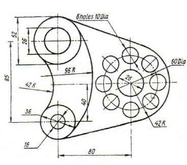
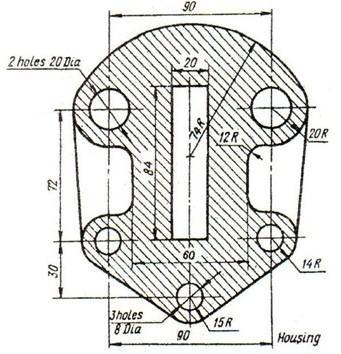
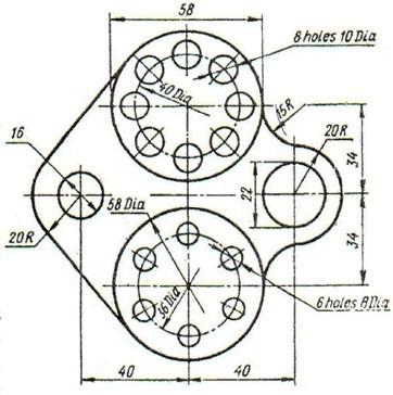
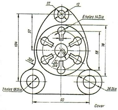
39 Chapter Two Problems Problem 2.1 :- draw the following features on an A3 sheet ( all dimensions in mm )
40
41 6-7- Problem 2.2 :- redraw the following lines and divide each one to the required number of equal segments a- b- 41
42 7- using the dividing method Problem 2.3:- redraw the following squares on an A3 sheet and divide each one to the required number of identical squares a- b- Problem 2.4:- transform the following angels and divide them to the required number of identical angels 42
43 Problem 2.5:- draw the following triangles on an A3 sheet Problem 2.6:- draw the following tangency on an A3 sheet and point the tangency center and the tangency points
44 5- Problem 2.7:- draw the following features on an A3 sheet
45
46
47
48

49

50
51

52

53

54
55
56 56
57 57
58 CHAPTER THREE ORTHOGARPH PROJECTION Section 3.1 introduction Section 3.2 multi view drawing Views of a solid revolving of object and regular views Necessary views Two and one views Hidden and center lines Alignment of the views Priorities of the drawing lines in multi view drawing Section 3.3: Orthogonal projections Introduction The glass box method Surfaces, edges and corners in orthographic projection Adjacent areas and similar shapes of a surface o line ( miter line ) orthographic projection techniques projection of basic objects Alternative position of views partial views Section 3.4: First and third angle views First angle projection third angle projection Section 3.5: sectioning objective lines in sectioning Sectioning techniques Section types 58
 object (ie.")
59 CHAPTER THREE: PROGECTION Section 3.1: introduction The most important objective of the engineering drawing is to transfer information between the designer and the executer. All the designing processes end with a three dimensional configuration in the designer mind which can be drawn in a piece of paper. However, drawing the 3-D ( three dimensional ) object (ie. Solid ) will not give the full description for the design and some details may be lost. In the 18 th century, a French mathematics and engineer Gaspand Monge ( ), who was involved with the design of military armory, developed using two planes of projections at right angel to each other a graphical description for a solid and this system was called and still the descriptive geometry. Monge s descriptive geometry set the basic for what now is known as the orthographic projection. Monge s method is illustrated in figure 3.1. Figure 3.1. Monge s descriptive geometry In this method, the 3-D solid is described by two perpendicular projection planes. In this chapter, we will discus many rules and techniques for the orthographic projection Section 3.2: multi view drawing Views of a solid In previous chapter, we describe many methods which are used to sketch a 3-D solid such as perspective, isometric,, etc. Although these methods are used widely, they are not in some cases enough for describing an engineering design due to the lake of dimensions or non true dimensions or shapes. So, for engineering prepuces, engineers transform their 3-D solid to many 2-D ( two dimensional) drawings called projections that fully describe the object or solid with all true dimensions and shape. These drawings are called views). Views for an object must be arranged a system which is called multi view projection. In this system, each view gives a piece of information about the object. However, one view in most of times is not enough. These views are front, rear, top, bottom, left and right. The concepts of these 59

60 Views will be discussed later. There are many types of viewing and projection for this level, we will be enough with the orthogonal projection due to its simplicity and popularly. For views: the front view is been observed directly from the observer, the rear is the opposite view to the front view. The top view is the up view of the object from the viewing side of the viewer, the bottom view is the opposite view of the top view. The right and left views are the left and the right of object respectively Revolving of object and regular views You can obtain the front view by observing the object directly. However, the obtaining the other views such as top, left,, etc will be some how difficult due to the hidden features in the solid. So, you are obligated to revolve the object to see or observe all the views you need. The revolving process is constrained by a certain angel to be all views orthogonal which is 90 o so you revolve the object by 90 o over x,y or z axis to and made the view you want as frontal view. In many cases, you cannot revolve the object because its either too heavy or its still an idea in the designer mind so you are obligated to imagine the revolving process which is in our course will be the most applicable way for projection. From other hand, there are views are a regular ( common ) views that used to describe an object which are : the front, the top and right or left views. All these views are drawn on the same paper and they must be spaced in adequate way to insure no interference between the views and there is an enough space for the dimensioning, naming,, etc. An example for the concept of all viewing is illustrated in figure (3.2) Figure 3.2. six view illustration 61

61 3.2.3 Necessary views As said before, there are six views are used to describe a three dimensional object. However, in many cases there are no need to draw all these views which reduce the effort and confusing for engineering drawing reader. The choice of necessary views depends on many parameters such as:- 1- Dimension: chose the most dimension view for the opposite views ( eg. Right and left views ) 2- Hidden lines: chose the less hidden lines view 3- Identical views: if there are two or more identical views, there is no need to draw all views unless there is a need for display the dimensions 4- Fillets, corners,, etc. ( ie. Details ): chose the most describing views which has the most details However, the most common views are the Top ( T ), Front ( F ) and Side ( L or R ) views and for this level, these are the most common views that we will deal with Two and one views In many cases, two or even one view is more than enough to fully describe the object and in most cases, the top and front or side views are been chosen for that job. However, the one view drawing is used when all the dimension of the object is descried in one view except one dimension ( ex. The thickness or depth ) which can be insert to the drawing as a note. Figure 3.3 illustrate an object needs one view with some notes to describe it fully Hidden and center lines Figure 3.3. object needs one view with some notes to describe it fully As said in chapter one, the hidden lines are used to draw the invisible lines. In views drawing, hidden lines are too important because it describe an object specifications as shown in figure 3.4. ( see the next page ) There are some rules that must be followed when a hidden line is being drawn to have a correct and adequate drawings and some f these rules are:- 61
62 1- Hidden lines must join the visible lines when there is a drawing of hidden line between two visible lines 2- When the hidden line is drawn from a center of two visible line, a gap must be left to distinguish the visible lines 3- When two hidden lines intersect or form a corner, the small dashes must joint to form T or L shapes 4- When a hidden lines intersect a visible line, the hidden line must jump over the visible line ( ie. The gap between dashes is located at the intersection point ) 5- Two hidden lines must be staggered ( ie. The dashes must not symmetrical ) 6- Try to reduce the number of hidden lines by omitting the unnecessary lines Figure 3.4. an example of usage of hidden and center lines Center line is used to describe the symmetry in parts and it is important to draw these lines inside the views. The center lines have,also, many rules and some of these rules are:- 1- When two or more center lines are intersected, they must intersect at the center of the small dashes 2- The center lines must extend outside the feature for about 8 10 mm 3- Never start or end a center line by the small dash 4- You can magnified the size of the center line depending on the size of the drawing 5- For small holes, you can make the center lines continues The rules for both hidden and center lines are illustrated in figure 3.5 ( see the next page) 62
63 Figure 3.5. hidden and center lines rules Alignment of the views In the previous sections, we introduce the multi viewing principles. One of the most important principle of this technique is the alignment of the views. As in the other principles of the engineering drawing, the views alignment follows many standards such as :- 1- You must draw all the views line up with the front view 2- Never mix up with the views positions ( ie. The top is up the front and the bottom is down, the left view is to the left and the and the right view is to the right The most common methods for the multi view drawing are the 1 st and 3 rd angle projection which we will discuss in section Priorities of the drawing lines in multi view drawing In some cases, a hidden line is drawn in the same place of a visible line or in the place of a center line or,, etc. you can t draw both lines in the same place, so you need to give a priority for one line over the other. The priority rule is simple and it is illustrated in figure 3.6 Section 3.3: Orthogonal projections Introduction Visible line > Hidden line > Center line Figure 3.6. multi view drawing priorities rule From its name, the orthogonal projection is views generated by projections of horizontal and vertical lines from the object points on a parallel plane to the projected face. In other word, to have an orthogonal views you must look to the object from a far distance where the object is on the edge level. There are two types of the orthogonal projections which are :- 1- First ( 1 st ) angle projection 63
64 2- Third ( 3 rd ) angle projection Both of these projection types will be discussed in following sub-sections The glass box method The glass box method is one of the oldest methods in the orthographic projection history. In this method, the object is assumed to be inside a cubic glass box where the faces of the box are parallel to the principle faces of the object and the projections on the six faces of the glass box are the orthogonal projections of the object. Principle planes the planes which are perpendicular to the x-y, x-z and y-z planes and parallel to the other planes In this method, the observer looks from a so far distance to each face of the glass box perpendicularly and draw what he/she saw on that face of the glass box and repeat these two steps for the rest five faces, then the observer unfold the glass box to bring all the faces in the same plane to get the orthogonal projections. However, not all these views are necessary as said before and the unfolding process will transform the object from three dimensional to two dimensional description. The unfolding process is constrained by some rules such as :- 1- All the views,except the rear., are connected to the front face 2- Revolve the faces outward from the original box until all planes are in the same plane 3- The rear plane is connected to the left plane Figure 3.7 illustrate the steps of the usage of the glass box method ( see the next page ) The process of unfolding will deicide weather the projection is 1 st or 3 rd angle projection 64
65 Figure 3.7. glass box method ( 3rd angel unfolding ) Surfaces, edges and corners in orthographic projection Any object is constructed by points and the process is: the movement of a point ( which is dimensionless; 0D ) will generate a line ( which is one dimension; 1D ), the movement of a line will generate a plane ( which is two dimension; 2D ) and finally the movement of a plane will generate an object ( which is three dimension; 3D ). The projections of an object depends on the orientation of the object and many rules that constrain the size of the projections it self because of the visual illusion ( خداع بصري ) that may happen due to the observation for a long period of time. In other word, the size of the projection may or may not be the true size of the object. The basic cases are found in the orthographic projection are: 1- When a line in the object is parallel to two glass box faces and perpendicular to the third, it will appears in true size ( TS ) in these two planes and as point in the third plane 2- When a line in the object is a parallel to only one of the glass box face, it will appears as TS in this plane and as a line in not true size ( shorter ) in the other two faces 3- When a line in the object is not parallel to any of glass box faces, it will appears in not true size ( shorter ) in all the faces 4- In general if a line lies on a plane, it will appears in TS in that plane 65

66 5- When a surface in the object is perpendicular to two of the glass box faces, it will appears in that faces as a edge and in the third face as a TS 6- When a surface in the object is perpendicular to one of the glass box faces, it will appears in that face as a edge and in the other faces as planes in not TS 7- When a surface is not perpendicular to any faces, it will appears as planes in not TS in all faces The other cases are a product of these cases. However, the most important thing here is to understand the principles of orthographic projection when the object is fitted in the glass box where the most of its planes are principle. For the other cases where the most of the object planes aren t principles, other projection methods, such as the oblique projection, is used Adjacent areas and similar shapes of a surface The 3D object, in many cases, is constructed by many other small other objects, for example, the vehicle engine is assembly of many components which are pieces of other small principle objects such as cubic, cones,, etc. In summary All the objects however what its complicity is constructed by a basic or principle objects and the projection of these objects will generate what known as the adjacent areas Due to the similarity between the principle objects, their projections will be similar and that known as the similar shapes in a surface( eg. The rectangle shape, triangle shape,, etc ) o line ( miter line ) In orthographic projection, many dimensions are repeated in two or more views and because of that you can draw the dimension one time and project it in the other views. This procedure will reduce the time and the effort and will generate more adequate drawing. To project a dimension on the other views, a magic line called the miter line or the 45 o line. This line is used due to the right angle theories as illustrated in figure
67 The importance of this line will be shown later orthographic projection techniques Figure 3.8. miter line principle After introducing a brief description in the previous sections, now it is the time to introduce the techniques behind this method of engineering drawing. As in other engineering drawing methods, orthographic projection has many techniques to reduce the time and the effort and to generate a correct and adequate drawing to be easy to be read by other engineers. In the orthographic projection, the sequence of steps is important to prevent the wasting in redrawing or the correction of the mistakes in the drawn views. The adequate sequence for the orthographic projection drawing is :- 1- Fix the paper on the drawing table ( see section 1.8 ) 2- Calculate the maximum dimension in the object. This step will help you in zoning your paper for the optimal situation 3- Divide the paper according to the views of maximum dimension to four sections not necessarily to be equal using phantom lines and if you found that your paper is not enough use a scale 4- Locate where the front, top and side view ( left or right ) will be and then draw the miter line by 0.5 mm 2H pencil from the center of the dividing lines intersection point 5- Draw a free hand sketch of the views on an external sheet of paper and be carful for the visible and hidden lines. This step will take a few minutes but it will reduce the waste of time and effort in correcting the future mistakes 6- Chose the most descriptive view and draw it on the drawing sheet by only repeating an accurate engineering drawing for your hand sketch 7- When you finish the first view, project the common dimensions to the second view and finish the other dimensions 67

68 8- The last view is,commonly, projected from the drawn two views with the assistant of the miter line In some cases, you chose the most descriptive view but there are some details in this view can be described better in other views. So, the descriptive view is the view that has the most details in the object not necessary all details. From the other hand, some view may have a unique detail that must be included after finishing the projections. It is better, in many cases, to draw the outlines of all views and then the descriptive details are drawn ; first the visible lines then the hidden lines. Remember that all the details in the object must be projected ( ie. All dimensions must be drawn) and because of that, it is preferred to check your drawing when you finish projection of basic objects All the complex objects are consist of basic object and to project these complex object, you need to project their basic shapes. In this subsection, we will introduce the projection of some common basic shapes in table 3.1 Table 3.1:- 3 rd angle projections of some common basic shapes in engineering drawing Object Shape Orthogonal projection Cylinder Object Shape Orthogonal projection Sphere 68


69 Cube Cone Object Shape Orthogonal projection Pyramid Hole Through drill Alternative position of views 69
70 in some cases where a flat object is being drawn using the traditional arrangement, a lot of space may be wasted and to reduce the waste in space, you can imagine the side or profile of the glass box is hinged with the top instead of the front which mean that the side view and the miter line will change places partial views In some cases where there is a symmetry or there are views aren t necessary in the projection, some of the views aren t drawn to reduce the waste in space, time and effort. In theses cases, the break line is used if the undrawn details are not necessary and either break or center line is used if there is symmetry in the view. However, it is preferred to draw all the details and all the views. An example of symmetry is illustrated in figure 3.9 Section 3.4: First and third angle views Figure 3.9. Partial viewing: symmetry case As said in the previous chapter, the first system we use to describe an object by two dimensional drawings is the descriptive geometry which was invented in the 18 th century by a French mathematician and engineer called Gaspand Monge. The descriptive geometry is the basic of the orthogonal projection. Nowadays, two types or methods of orthographic projection based on Monge s method are used and these types are the first and third angle projections First angle projection This method is common in Europe. Any object is putted in the first quadrant and viewed is projected by the first angle method. If we unfold the views for the first quadrant, we will get a 1 st angel projection. An illustration for the 1 st angle projection is shown in figure ( see the next page ) 71
71 3.4.2 third angle projection Figure First angle projection: (a) unfolding of glass box (b) the 2D views In this type, the object is located in the third quadrant and as in the 1 st angle projection if we unfold the views of the 3 rd quadrant we will get the 3 rd angle projections. An illustration for the 3 rd angle projection is shown in figure Figure Third angle projection: (a) unfolding of glass box (b) the 2D views Section 3.5: sectioning Objective The objective of the sectioning is to revel the inside details of the object. It is imagined to be cut or sectioned along a plane called the cutting plane. The nearest plane to the viewer is removed and the remain details are observed. We can summarize the objectives of sectioning as:- 1- Clarifying internal details 2- Reduce the number of hidden lines 3- Aid dimensioning 71
72 4- Show cross sectioning shape 5- Clarifying an assembly lines in sectioning As said before, one of the objectives for doing sectioning is to reduce the number of the hidden lines. However, there are other lines that are involved and each line has its own function and specifications. The most interesting lines are:- Visible line:- all the visible lines reveled after the removing of one half must be drawn Hidden lines:- in the section view ( ie. The view where the cutting plane is touching ), there must be no hidden lines. So, you change the revel lines to visible lines and forget about the other lines Cutting plane line:- see chapter one Hatching lines:- a- Hatching lines must indicates the material type b- A typical hatching lines ( that what we will use in this course ) is a 3mm 2H parallel inclined lines by 45 o with separating distance of 8mm c- The hatching line must start from a visible line and end by another visible line d- The hidden lines must not intersect with a hatching lines e- Changing the hatching lines means changing the material types f- The hatching lines must be uniformed in thickness and intensity g- When the hatching lines start and end form 45 o inclined lines, the angle of the hatching lines must be changed ( eg. 40 o ) Note In some analogs, even the planes that are a material and not be touched by the cutting plane are been hatched to indicate a material for a manufacturing reasons Sectioning techniques To do a sectioning, you need to follow these procedures 1- Draw all the views except the sectioning view as in regular projection 2- Draw the cutting line in its particular view ( ie. The view where the cutting plane appear as an edge ) 3- Draw the sectioning view and in this time draw only the visible lines 4- Imagine the cutting plane cuts the object 5- Remove the part that in opposite direction to the cutting line arrow 6- Look to the remain part in the same direction of the cutting line arrow 7- Change the hidden lines to visible lines 8- Hatch when the cutting plane touch a material Section types 72


73 full section In this section, a one cutting plane cuts the whole body. This type is used,generally, when there is a symmetry in the object. A full sectioning divides the object into two equal parts (ie. Identical parts ) as shown in figure Figure Full section Half section This type is used when there is a symmetry over two axes and/or when there an internal details must be reveled. Figure 3.13 illustrate this type of section Figure Half section Broken out section 73


74 This type is used,usually, when there are many internal details to revel and there is no symmetry in any axis and when it is necessary to expose only a small portion of the internal shape of an object but not enough to warrant a full or half section. Figure 3.14 illustrate this type ( see the next page ) Offset section Figure Broken out section This type is used, usually, when there are many internal details to revel and there is symmetry for each individual detail. Figure 3.15 illustrate this type Revolved section Figure Offset section This type is used when there are some small internal details as shown in figure to revel these details you need to make a sectioning but in this time there is no need for the imaginary process mentioned previously, you just need to revolve the crossed section part ( ie. What the cutting plane touch ) over its symmetry axis. 74

75 Figure Revolved section 75
76 CHAPTER FOUR DIMENSIONING Section 4.1: Introduction section 4.2: dimensioning rules Section 4.3: common dimensioning types and cases dimensioning a feature not drawn to scale chain dimensioning and auxiliary dimensioning parallel dimensioning Running dimensioning Dimensioning a circle arc dimensioning Angular dimensioning Chapter three and four problems 76
77 CHAPTER FOUR: DIMENSIONING Section 4.1: Introduction Dimensioning is the last part of the projection drawing. It has its own importance and should be drawn following standards to produce an adequate drawing which can be easily read and met all the stages of manufacturing. Dimensioning helps the manufacturer to know the size, location,..etc. of the object components. Each object is composed of many other simple objects and so, the views been drawn for an object is composed of many simple shapes such as circles, squares, rectangles, triangles,, etc. In all manufacturing processes the manufacturer needs to know the size of each simple shape ( ie. Width, height, depth, diameter or radius ), its location ( ie. The x, y and z dimensions ) and surface texture ( ie. Material, mechanical properties,, etc). To specify the size of a component of the object, you need to know its geometry and to specify the location, you need to define a datums to take the position from. You can chose the datums that you want, however, you can t take the edges of the glass box or an inadequate internal edges. Its preferable to use the object outlines for this prepuce. To specify the surface texture, you need to use a leader line with. noting system section 4.2: dimensioning rules As in all engineering drawing principles, dimensioning is governed by many standards. The best standard that we will use here is the British Standard ( BS ) 8888 because it covers all the ISO rules. A standard dimensioning of a one dimension is illustrated in figure 4.1 Figure 4.1. a standard dimensioning configuration The BS 8888 are:- 1- The dimension line is a continuous line of thickness 0.35 mm and HB intensity 2- The dimension line is drawn outside the outline of the object 3- A gap of 2 3 mm must be left between the projection line and the drawing 4- The projection line must extend of a distance 2 3 mm from the dimension line ( ie. Passing the arrow head ) 5- The arrow head should be triangles as possible as could, must touch the projection line that refer and must be filled 6- An enough space must be left from the dimension line for the dimension ( ie. Text ). 12 mm is recommended 7- Never use a center line as a dimension line. However, it can be used as a projection line 8- Dimension must be draw with the minimum umber of significant figures ( eg. 4 not 4.0) and when a decimal is used, use a comma as the decimal marker not the dot ( eg. 4,1 not 4.0 ) because the dot isn t clearly distinguished 9- The dimension line mustn t crossed with each other 77
78 10- Dimension must be drawn horizontal or in manner that can be read if the drawing is turned clockwise 11- The leader line must end with arrow head. In most cases, the leader line is used to give a hole dimension. In this case, the arrow head must be towards the center of the hole and must end at the circumferences of the hole There are recommendations for dimensioning to simplify the process and to ensure that there are no mistakes that will cost a waste in time and effort. Some of these recommendations are:- 1- Understand the shapes in the drawing to be able to chose the best dimensioning situation 2- Notes the space you have ad the complicity of the drawing to have a picture of where are the best possible positions for the dimensions 3- Placing the dimensions outside the drawing outline is the best choice 4- You can use a parallel or chain dimensioning types which one is applied, these types of dimensioning are discussed clearly later 5- Don t repeat a common dimension between two views instead put this dimension between these two views 6- In projection views, never extend the projection lines of the dimension to cross the folding lines 7- Try to make the dimension as could as possible orthogonal Figure 4.2 illustrate an example of the correct and in correct dimensioning Remember how is your drawing is good and clean is the standard of your adequacy and your engineering sense Section 4.3: common dimensioning types and cases dimensioning a feature not drawn to scale When you draw a feature without scale and you want not to create a misunderstanding to your drawing, you must underline the dimension as shown in figure 4.3 Figure 4.3. dimensioning of a feature not drawn to scale 78
79 Figure 4.2. A correct and incorrect dimensioning example chain dimensioning and auxiliary dimensioning Chain dimensioning means: the end projection lines for ne dimension is the beginning projection line for the adjacent dimension as illustrated in figure 4.4 Figure 4.4. Chain dimensioning and auxiliary dimensioning type This type of dimensioning is used where:- 1- The possible accumulation of the tolerances dose not endanger the function of the part ( ie when its been manufactured, it will not be a significant problem ) 2- When there is no enough space ( eg. The dimension must be drawn between the feature outline and the folding lines ) In this type of dimensioning, many rules must be followed and these rules are:- 1- The dimensions must be aligned to each other ( ie. Must be in the same level ) 79
80 2- An auxiliary dimension ( ie. The accumulation dimension ) is used when there is a suspects in the accuracy of the manufacturing process will be effective 3- Never use this dimensioning when the dimensions are small to keep the drawing clear and clean parallel dimensioning Parallel dimensioning means: the first projection line ( datum ) for the first dimension is the first datum for all of the rest dimensions as illustrated in figure 4.5 Figure 4.5. Parallel dimensioning type This type of dimensioning is more accurate than the chain dimensioning due to the common datum been used instead of the accumulated datums. This type is used on the opposite situation to the chain dimensioning and it has some rules to be followed such as:- 1- Never stuck the dimensions. Left an acceptable distance between the dimensions. 8 mm is recommended 2- The dimensioning must be at the same side of the feature as could as possible 3- There are no need for an auxiliary dimension here so all the dimension must be drawn Running dimensioning Running dimensioning is a simplified type of parallel dimensioning and it s a space saving type. This type is illustrated in figure 4.6. Note the circle in the first projection line 81

81 Figure 4.6. Running dimensioning type Dimensioning a circle A circle is been dimensioned by its diameter or radius and its center location. The symbol Φ is used for the diameter and the letter R is used for radius. The position of the center is located by tow dimensions from two datums. When the circle is large enough, the dimension is drawn inside the circle When the circle is small, the dimension line is drawn inside the circle and the dimension is drawn outside When the circle is too small, a two crossing lines instead of the center lines are used and the dimension is drawn with an arrow pointed to the circle or the dimension can be drawn orthogonally as shown in figure 4.7. Figure 4.7. Circle dimensioning Note The best dimensioning is when there are projection views are involved is the orthogonal ( ie. Vertical or horizontal ) dimensioning When the space isn t enough for dimension line, you can reverse the arrow heads to be outside the projection lines arc dimensioning As said before, the an arc is a part of a circle and to dimension it you need to define its radius and the location of the center as shown in figure Angular dimensioning Figure 4.8. arc dimensioning 81
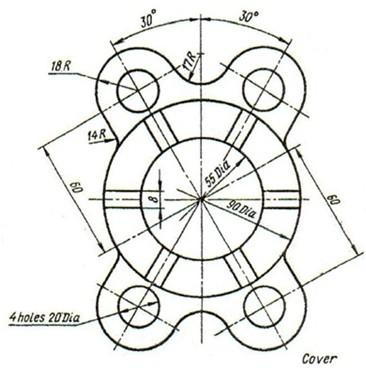
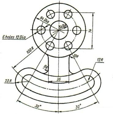
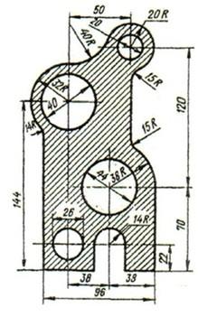
82 Angels are the radian measurement between two intersection lines and so to dimension an angle you need to know its value. A typical cases of dimensioning are shown in figure 4.9. Figure 4.9. angular dimensioning Chapter Three and Four Problems Problem 1:- Draw the projection for the following objects on an A3 sheet and dimension it correctly. Be awareness to the sectioning
83
84 4.6 84
85 85
86
87
88
89
90
91
92
93
94
95
96
97
98 98
99
100

101 4.36 CHAPTER FIVE: PICTORIAL DRAWING 111

102 The word pictorial means like picture. it refers to any realistic form of drawing. Pictorial drawings show height, width and depth. The most popular two types is the obliqe drawing which is the simplest one, and the isometric drawing. 5.1 Oblique drawing: An oblique drawing shows objects with one or more parallel faces having ture shape and size. A scale is selected for the front face, then an angle for the depth (receding axis) is chosen. The three types of oblique drawing depends on the scale of the receding axis. The receding axis is drawn at half scale for a cabinet oblique drawing, at full scale for a cavilier, and with ¾ scale for general type. Figure 5.1. oblique drawings types 5.2 Isometric drawing: Isometric drawing is more realistic than the oblique. The entire object appears as if it is tilted to award the viewer. The word isometric means equal measure. This equal measure refers to the angles between the three a es (1 0 ) after the object has been tilted. Figure 5.2. isometric drawing Producing isometric drawings: 112


103 1- Using the T squre draw a hirizantal line, the by the triangle draw a vertical line at the center of the horizontal one. Figure 5.3. producing isometric step 1 2- Using the T-square and the 30 0 triangle draw 30 line to the right, and another to the left. Figure 5.4. producing isometric step 2 3- Plot the principal height on the z axis, width on the x axis, and depth on the y axis. Figure 5.5. producing isometric step 3 113
104 4- Specify the start point to draw on the drawing and on the exercise, then draw the lines parallel to the z axis using the vertical edge of the triangle, lines that parallel to the x axis draw it using the 30/60 triangle as the axis drawn before, also the lines that parallel to the y axis. 5- To draw inclined lines that dousent parallel to any of axes, specify the start and end points the match togather. Figure 5.6. producing isometric step Drawing isometric circles: Circles in isometric planes appear as ellipses. To draw acircle on left plane and diameter equal to D, follow the procedure based on the figure below: Figure 5.7. drawing isometric circle steps a- Specify the the center of the circle on the isometric plane. 114
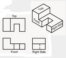
105 b- Draw tow center lines from the center, vertical and 30 to left. c- Draw a square of edge length equal D, and the center lines should devide each side by half. d- Draw the lines 1-2, 1-3, 4-5 and 4-6. e- Point 7 is the intersection between lines 1-2 and 4-5, and similarly point 8 the intersection of 1-3 and 2-6. Set your compass to the distance 7-2, draw an arc with center at 7 from point 2 to 5, do the same from point 8. f- Set your compass to the distance 1-2, draw an arc with center 1, from 2 to 3, and same thing from point Orthographic to isometric drawings: To convert an orthographic projection views to an isometric drawing (2D views to 3D model) read the hints below: 1- Identify major features and overall dimensions. 2- Draw the axes, then draw a boundary box using construction lines. 3- Only measure dimensions along aprimary axes 4- Do not directly transfer angles from a Multiview to a pictorial. 5- Sketch faces roughly, starting with normal faces. For example if we have the orthographic views below To draw the isometric drawing : 1- Draw isometric axes. Figure 5.8. ortho to iso example 115
106 2- Estimate the overall hight, width and depth, and sketch the boundary box 3- Sketch the outlines of the views on the box, starting with isometric lines. 4- Locate start and end points for inclined lines and sketch.. Examples: 116
107 117
11/12/2015 CHAPTER 7. Axonometric Drawings (cont.) Axonometric Drawings (cont.) Isometric Projections (cont.) 1) Axonometric Drawings
 Axonometric Drawings (cont.) Isometric Projections (cont.) 1) Axonometric Drawings") CHAPTER 7 1) Axonometric Drawings 1) Introduction Isometric & Oblique Projection Axonometric projection is a parallel projection technique used to create a pictorial drawing of an object by rotating the
CHAPTER 7 1) Axonometric Drawings 1) Introduction Isometric & Oblique Projection Axonometric projection is a parallel projection technique used to create a pictorial drawing of an object by rotating the
Copyrighted Material. Copyrighted Material. Copyrighted. Copyrighted. Material
 Engineering Graphics ORTHOGRAPHIC PROJECTION People who work with drawings develop the ability to look at lines on paper or on a computer screen and "see" the shapes of the objects the lines represent.
Drawing sheet: - The various size of the drawing sheet used for engineering drawing as per IS Are listed in the table
 Dronacharya Group of Institutions, Greater Noida Computer Aided Engineering Graphics (CAEG) (NCE 151/251) List of Drawing Sheets: 1. Letter writing & Dimensioning. 2. Projection of Points & Lines. 3. Projection
Multi-View Drawing Review
 Multi-View Drawing Review Sacramento City College EDT 300/ENGR 306 EDT 300 / ENGR 306 - Chapter 5 1 Objectives Identify and select the various views of an object. Determine the number of views needed to
Student Name: Teacher: Date: District: Rowan. Assessment: 9_12 T and I IC61 - Drafting I Test 1. Description: Unit C - Sketching - Test 2.
 Student Name: Teacher: Date: District: Rowan Assessment: 9_12 T and I IC61 - Drafting I Test 1 Description: Unit C - Sketching - Test 2 Form: 501 1. The most often used combination of views includes the:
Multiview Drawing. Definition: Graphical representation of a 3- dimensional object on one plane (sheet of paper) using two or more views.
 using two or more views.") Multiview Drawing Definition: Graphical representation of a 3- dimensional object on one plane (sheet of paper) using two or more views. Multiview Drawing Another name for multiview drawing is orthographic
Multiview Drawing Definition: Graphical representation of a 3- dimensional object on one plane (sheet of paper) using two or more views. Multiview Drawing Another name for multiview drawing is orthographic
Multiviews and Auxiliary Views
 Multiviews and Auxiliary Views Multiviews and Auxiliary Views Objectives Explain orthographic and multiview projection. Identifying the six principal views. Apply standard line practices to multiviews
UNIT 5a STANDARD ORTHOGRAPHIC VIEW DRAWINGS
 UNIT 5a STANDARD ORTHOGRAPHIC VIEW DRAWINGS 5.1 Introduction Orthographic views are 2D images of a 3D object obtained by viewing it from different orthogonal directions. Six principal views are possible
Unit 4: Geometric Construction (Chapter4: Geometry For Modeling and Design)
") Unit 4: Geometric Construction (Chapter4: Geometry For Modeling and Design) DFTG-1305 Technical Drafting Instructor: Jimmy Nhan OBJECTIVES 1. Identify and specify basic geometric elements and primitive
Unit 4: Geometric Construction (Chapter4: Geometry For Modeling and Design) DFTG-1305 Technical Drafting Instructor: Jimmy Nhan OBJECTIVES 1. Identify and specify basic geometric elements and primitive
ORTHOGRAPHIC PROJECTION
 ORTHOGRAPHIC PROJECTION C H A P T E R S I X OBJECTIVES 1. Recognize and the symbol for third-angle projection. 2. List the six principal views of projection. 3. Understand which views show depth in a drawing
ENGINEERING DRAWING. 1. Set squares are used to draw different angles. What is the angel a formed by the 45⁰ set square? Give a brief answer.
 ENGINEERING DRAWING 1. Set squares are used to draw different angles. What is the angel a formed by the 45⁰ set square? Give a brief answer. 2. Which is the correct method of hatching a plane surface?
CHAPTER 01 PRESENTATION OF TECHNICAL DRAWING. Prepared by: Sio Sreymean
 CHAPTER 01 PRESENTATION OF TECHNICAL DRAWING Prepared by: Sio Sreymean 2015-2016 Why do we need to study this subject? Effectiveness of Graphics Language 1. Try to write a description of this object. 2.
Engineering Graphics, Class 8 Orthographic Projection. Mohammad I. Kilani. Mechanical Engineering Department University of Jordan
 Engineering Graphics, Class 8 Orthographic Projection Mohammad I. Kilani Mechanical Engineering Department University of Jordan Multi view drawings Multi view drawings provide accurate shape descriptions
Chapter 2 Using Drawing Tools & Applied Geometry
 Chapter 2 Using Drawing Tools & Applied Geometry TOPICS Preparation of Tools. Using of Tools Applied Geometry PREPARATION OF TOOLS Fastening Paper to Drafting Board 1. Place the paper close to the table
CE 100 Civil Engineering Drawing Sessional (Lab Manual)
") CE 100 Civil Engineering Drawing Sessional (Lab Manual) Department of Civil Engineering Ahsanullah University of Science and Technology November, 2017 1 Preface This course is designed to provide civil
CE 100 Civil Engineering Drawing Sessional (Lab Manual) Department of Civil Engineering Ahsanullah University of Science and Technology November, 2017 1 Preface This course is designed to provide civil
(As per New Revised Syllabus of Anna University) Department of Mechanical Engineering. SATHYABAMA UNIVERSITY Jeppiaar Nagar, Chennai
 Department of Mechanical Engineering. SATHYABAMA UNIVERSITY Jeppiaar Nagar, Chennai") (1*,1((5,1* *5$3+,&6 (As per New Revised Syllabus of Anna University) Dr. S.RAMACHANDRAN, M.E., Ph.D. Professor & Head K. PANDIAN, M.E., E.V.V.RAMANAMURTHY, M.Tech., R. DEVARAJ, M.E., Associate Professors
(1*,1((5,1* *5$3+,&6 (As per New Revised Syllabus of Anna University) Dr. S.RAMACHANDRAN, M.E., Ph.D. Professor & Head K. PANDIAN, M.E., E.V.V.RAMANAMURTHY, M.Tech., R. DEVARAJ, M.E., Associate Professors
Chapter 5 Pictorial sketching
 Chapter 5 Pictorial sketching Contents Freehand sketching techniques Pictorial projections - Axonometric - Oblique Isometric projection vs isometric sketch Isometric sketch from an orthographic views Isometric
CLASS views from detail on a grid paper. (use appropriate line types to show features) - Optional views. Turn in for grading on class 6 (06/04)
 - Optional views. Turn in for grading on class 6 (06/04)") CLASS 4 Review: - Projections - Orthographic projections Lab: - 3 views from detail on a grid paper. (use appropriate line types to show features) - Optional views. Turn in for grading on class 6 (06/04)
CLASS 4 Review: - Projections - Orthographic projections Lab: - 3 views from detail on a grid paper. (use appropriate line types to show features) - Optional views. Turn in for grading on class 6 (06/04)
1 st Subject: 2D Geometric Shape Construction and Division
 Joint Beginning and Intermediate Engineering Graphics 2 nd Week 1st Meeting Lecture Notes Instructor: Edward N. Locke Topic: Geometric Construction 1 st Subject: 2D Geometric Shape Construction and Division
Orthographic Projection
 Orthographic Projection Why Orthographic Projection is used in technical drawing Orthographic projection is a method of producing a number of separate two-dimensional inter-related views, which are mutually
MODELING AND DESIGN C H A P T E R F O U R
 MODELING AND DESIGN C H A P T E R F O U R OBJECTIVES 1. Identify and specify basic geometric elements and primitive shapes. 2. Select a 2D profile that best describes the shape of an object. 3. Identify
Chapter 5 SECTIONS OF SOLIDS 5.1 INTRODUCTION
 Chapter 5 SECTIONS OF SOLIDS 5.1 INTRODUCTION We have studied about the orthographic projections in which a 3 dimensional object is detailed in 2-dimension. These objects are simple. In engineering most
ENGINEERING GRAPHICS 1E9
 Lecture 3 Monday, 15 December 2014 1 ENGINEERING GRAPHICS 1E9 Lecture 3: Isometric Projections Lecture 3 Monday, 15 December 2014 2 What is ISOMETRIC? It is a method of producing pictorial view of an object
Sketching Fundamentals
 Sketching Fundamentals Learning Outcome When you complete this module you will be able to: Make basic engineering sketches of plant equipment. Learning Objectives Here is what you will be able to do when
technical drawing
 technical drawing school of art, design and architecture nust spring 2011 http://www.youtube.com/watch?v=q6mk9hpxwvo http://www.youtube.com/watch?v=bnu2gb7w4qs Objective abstraction - axonometric view
Chapter 1 Overview of an Engineering Drawing
 Chapter 1 Overview of an Engineering Drawing TOPICS Graphics language Engineering drawing Projection methods Orthographic projection Drawing standards TOPICS Traditional Drawing Tools Lettering Freehand
ENGINEERING GRAPHICS ESSENTIALS
 ENGINEERING GRAPHICS ESSENTIALS Text and Digital Learning KIRSTIE PLANTENBERG FIFTH EDITION SDC P U B L I C AT I O N S Better Textbooks. Lower Prices. www.sdcpublications.com ACCESS CODE UNIQUE CODE INSIDE
2003 Academic Challenge
 Worldwide Youth in Science and Engineering 2003 Academic Challenge ENGINEERING GRAPHICS TEST - REGIONAL Engineering Graphics Test Production Team Ryan Brown, Illinois State University Author/Team Coordinator
DELHI TECHNOLOGICAL UNIVERSITY ENGINEERING GRAPHICS LAB MANUAL
 DELHI TECHNOLOGICAL UNIVERSITY ENGINEERING GRAPHICS LAB MANUAL NAME: - ROLL NO: - GROUP: - BRANCH: - GROUP TEACHER: Page 1 www.rooplalrana.com 1 GENERAL INSTRUCTIONS FOR ENGG. GRAPHICS LAB 1) Students
Technological Design Mr. Wadowski. Orthographic & Isometric Drawing Lesson
 Technological Design Mr. Wadowski Orthographic & Isometric Drawing Lesson TOPICS Working Drawings, Isometric Drawings & Orthographic Drawings Glass box concept Multiview projection Orthographic projection
Engineering Graphics Essentials with AutoCAD 2015 Instruction
 Kirstie Plantenberg Engineering Graphics Essentials with AutoCAD 2015 Instruction Text and Video Instruction Multimedia Disc SDC P U B L I C AT I O N S Better Textbooks. Lower Prices. www.sdcpublications.com
Isometric Drawing Chapter 26
 Isometric Drawing Chapter 26 Sacramento City College EDT 310 EDT 310 - Chapter 26 - Isometric Drawing 1 Drawing Types Pictorial Drawing types: Perspective Orthographic Isometric Oblique Pictorial - like
ENGINEERING GRAPHICS ESSENTIALS
 ENGINEERING GRAPHICS ESSENTIALS with AutoCAD 2012 Instruction Introduction to AutoCAD Engineering Graphics Principles Hand Sketching Text and Independent Learning CD Independent Learning CD: A Comprehensive
Engineering Graphics UNIVERSITY OF TEXAS RIO GRANDE VALLEY JAZMIN LEY HISTORY OF ENGINEERING GRAPHICS GEOMETRIC CONSTRUCTION & SOLID MODELING
 Engineering Graphics UNIVERSITY OF TEXAS RIO GRANDE VALLEY JAZMIN LEY HISTORY OF ENGINEERING GRAPHICS GEOMETRIC CONSTRUCTION & SOLID MODELING Overview History of Engineering Graphics: Sketching, Tools,
Guide To British Standards
 Guide To British Standards Higher Graphic Communication C O N T E N T S page TITLE BLOCK 2 DRAWING SCALES 2 LINE TYPES 3 ORTHOGRAPHIC PROJECTION 4 SECTIONAL VIEWS 4 SCREW THREADS & COMPONENTS 7 INTERUPTTED
ENGINEERING DRAWING. UNIT III - Part A
 DEVELOPMENT OF SURFACES: ENGINEERING DRAWING UNIT III - Part A 1. What is meant by development of surfaces? 2. Development of surfaces of an object is also known as flat pattern of the object. (True/ False)
Describing an Angle Bracket
 Basics of Drafting Describing an Angle Bracket Orthographic Projection Orthographic drawings represent three dimensional objects in three separate views arranged in a standard manner. Orthographic Views
GOVERNMENT POLYTECHNIC, VALSAD MECHANICAL ENGINEERING DEPARTMENT ASSIGNMENT SUB: MECHANICAL DRAFTING (C321901) TERM:172
 TERM:172") GOVERNMENT POLYTECHNIC, VALSAD MECHANICAL ENGINEERING DEPARTMENT ASSIGNMENT SUB: MECHANICAL DRAFTING (C321901) TERM:172 1) When all the dimension are placed above the dimension line, it is called (a) Aligned
GOVERNMENT POLYTECHNIC, VALSAD MECHANICAL ENGINEERING DEPARTMENT ASSIGNMENT SUB: MECHANICAL DRAFTING (C321901) TERM:172 1) When all the dimension are placed above the dimension line, it is called (a) Aligned
Chapter 5 Pictorial Projection
 Chapter 5 Pictorial Projection Objectives After completing this chapter, the students will be able to Create freehand sketches using the correct sketching techniques. Explainthe difference between axonometric
ISOMETRIC PROJECTION. Contents. Isometric Scale. Construction of Isometric Scale. Methods to draw isometric projections/isometric views
 ISOMETRIC PROJECTION Contents Introduction Principle of Isometric Projection Isometric Scale Construction of Isometric Scale Isometric View (Isometric Drawings) Methods to draw isometric projections/isometric
ORTHOGRAPHIC PROJECTIONS. Ms. Sicola
 ORTHOGRAPHIC PROJECTIONS Ms. Sicola Objectives List the six principal views of projection Sketch the top, front and right-side views of an object with normal, inclined, and oblique surfaces Objectives
Civil Engineering Drawing
 Civil Engineering Drawing Third Angle Projection In third angle projection, front view is always drawn at the bottom, top view just above the front view, and end view, is drawn on that side of the front
Engineering Graphics. Class 2 Drafting Instruments Mohammad Kilani
 Engineering Graphics Class 2 Drafting Instruments Mohammad Kilani Drafting Instruments A Design is as good as its instruments A engineering drawing is a highly stylized graphic representation of an idea.
Engineering Graphics, Class 5 Geometric Construction. Mohammad I. Kilani. Mechanical Engineering Department University of Jordan
 Engineering Graphics, Class 5 Geometric Construction Mohammad I. Kilani Mechanical Engineering Department University of Jordan Conic Sections A cone is generated by a straight line moving in contact with
Technical Graphics Higher Level
 Coimisiún na Scrúduithe Stáit State Examinations Commission Junior Certificate Examination 2005 Technical Graphics Higher Level Marking Scheme Sections A and B Section A Q1. 12 Four diagrams, 3 marks for
2004 Academic Challenge
 2004 Academic Challenge ENGINEERING GRAPHICS TEST - REGIONAL Engineering Graphics Test Production Team Ryan Brown, Illinois State University Author/Team Coordinator Kevin Devine, Illinois State University
JUNIOR CERTIFICATE 2009 MARKING SCHEME TECHNICAL GRAPHICS HIGHER LEVEL
 . JUNIOR CERTIFICATE 2009 MARKING SCHEME TECHNICAL GRAPHICS HIGHER LEVEL Sections A and B Section A any ten questions from this section Q1 12 Four diagrams, 3 marks for each correct label. Q2 12 2 marks
ORDINARY LEVEL PAST PAPERS
 ORDINARY LEVEL PAST PAPERS UNEB S4 1982 SECTION I PLANE GEOMETRY 1. (a) Construct a diagonal scale of 40mm to 10mm to read up to 20mm by 0.02mm. (b) Indicate on your scale the following readings. (i) 14.8mm.
Study Unit. Auxiliary Views. This sneak preview of your study material has been prepared in advance of the book's actual online release.
 Study Unit Auxiliary Views This sneak preview of your study material has been prepared in advance of the book's actual online release. iii Preview You re entering now into another subject area in your
ENGINEERING GRAPHICS
 ENGINEERING GRAPHICS Course Structure Units Topics Marks Unit I Plane Geometry 16 1 Lines, angles and rectilinear figures 2 Circles and tangents 3 Special curves: ellipse, parabola, involute, cycloid.
Activity 5.2 Making Sketches in CAD
 Activity 5.2 Making Sketches in CAD Introduction It would be great if computer systems were advanced enough to take a mental image of an object, such as the thought of a sports car, and instantly generate
Trade of Metal Fabrication. Module 6: Fabrication Drawing Unit 13: Parallel Line Development Phase 2
 Trade of Metal Fabrication Module 6: Fabrication Drawing Unit 13: Parallel Line Development Phase 2 Table of Contents List of Figures... 4 List of Tables... 5 Document Release History... 6 Module 6 Fabrication
DFTG-1305 Technical Drafting Prof. Francis Ha
 DFTG-1305 Technical Drafting Prof. Francis Ha Session 4 Orthographic Projection (or Multiview Projection) Reading: Geisecke s textbook: 14 th Ed. Chapter 5 p.162 15 th Ed. Chapter 6 p.232 Update: 18-0205
2009 Academic Challenge
 2009 Academic Challenge ENGINEERING GRAPHICS TEST STATE FINALS This Test Consists of 50 Questions Engineering Graphics Test Production Team Ryan Brown, Illinois State University Author/Team Leader Kevin
Beginning Engineering Graphics 3 rd Week Lecture Notes Instructor: Edward N. Locke Topic: The Coordinate System, Types of Drawings and Orthographic
 Beginning Engineering Graphics 3 rd Week Lecture Notes Instructor: Edward N. Locke Topic: The Coordinate System, Types of Drawings and Orthographic 1 st Subject: The Cartesian Coordinate System The Cartesian
DWG 002. Blueprint Reading. Geometric Terminology Orthographic Projection. Instructor Guide
 DWG 002 Blueprint Reading Geometric Terminology Orthographic Projection Instructor Guide Introduction Module Purpose The purpose of the Blueprint Reading modules is to introduce students to production
A Concise Introduction to Engineering Graphics
 A Concise Introduction to Engineering Graphics Fourth Edition Including Worksheet Series A Timothy J. Sexton, Professor Department of Industrial Technology Ohio University BONUS Book on CD: TECHNICAL GRAPHICS
Multiview Projection
 DFTG-1305 Technical Drafting Prof. Francis Ha Session 4 Multiview Projection (or Orthographic Projection) Reading: Geisecke s textbook: 14 th Ed. Chapter 5 p.162 15 th Ed. Chapter 6 p.232 Update: 17-0510
ENGINEERING GRAPHICS UNIT V ISOMETRIC PROJECTION PERSPECTIVE PROJECTION
 ENGINEERING GRAPHICS UNIT V ISOMETRIC PROJECTION PERSPECTIVE PROJECTION 1.PICTORIAL PROJECTIONS To visualize the shape of the whole object in its 3- D form, all the two or three orthographic views of the
APJ ABDUL KALAM TECHNOLOGICAL UNIVERSITY SECOND SEMESTER B.TECH DEGREE EXAMINATION, MAY PART A Answer ANY Two questions. 10 marks each.
 B B2B111 Pages: 2 Reg. No. Name: SECOND SEMESTER B.TECH DEGREE EXAMINATION, MAY 2017 Max.Marks:50 Course Code: BE110 Duration:3Hours Answer ANY Two questions. 10 marks each. 1. A line AB 100 mm long and
GOAL Practise techniques for creating various types of geometric lines by constructing and reproducing figures. sheet of letter-sized white paper
 TECHNIQUE STUDENT BOOK Chapter 11, page 340 TOOLBOX Pages 62 67 GOAL Practise techniques for creating various types of geometric lines by constructing and reproducing figures. MATERIALS drawing board T-square
DRAWING INSTRUMENTS AND THEIR USES
 Chapter - 1A DRAWING INSTRUMENTS AND THEIR USES Drawing Instruments are used to prepare neat and accurate Drawings. To a greater extent, the accuracy of the Drawings depend on the quality of instruments
Student Name: Teacher: Date: District: Rowan. Assessment: 9_12 T and I IC61 - Drafting I Test 2. Description: Drafting 1 - Test 6.
 Student Name: Teacher: Date: District: Rowan Assessment: 9_12 T and I IC61 - Drafting I Test 2 Description: Drafting 1 - Test 6 Form: 501 1. 2X on a hole note means: A. Double the size of the hole. B.
Isometric Drawings. Figure A 1
 A Isometric Drawings ISOMETRIC BASICS Isometric drawings are a means of drawing an object in picture form for better clarifying the object s appearance. These types of drawings resemble a picture of an
2009 Academic Challenge
 2009 Academic Challenge ENGINEERING GRAPHICS TEST SECTIONAL This Test Consists of 50 Questions Engineering Graphics Test Production Team Ryan Brown, Illinois State University Author/Team Leader Kevin Devine,
Period: Date Lesson 2: Common 3-Dimensional Shapes and Their Cross- Sections
 : Common 3-Dimensional Shapes and Their Cross- Sections Learning Target: I can understand the definitions of a general prism and a cylinder and the distinction between a cross-section and a slice. Warm
AutoCAD Tutor 2011 Support Docs
 AutoCAD Tutor 2011 Support Docs CHAPTER 1 CUSTOMIZING THE QUICK ACCESS TOOLBAR One of the advantages of the Quick Access Toolbar is the ability to display the AutoCAD commands that you frequently use.
3. The dimensioning SYMBOLS for arcs and circles should be given:
 Draft Student Name: Teacher: District: Date: Wake County Test: 9_12 T and I IC61 - Drafting I Test 2 Description: 4.08 Dimensioning Form: 501 1. The MINIMUM amount of space between two, ADJACENT DIMENSION
JUNIOR CERTIFICATE 2008 MARKING SCHEME TECHNICAL GRAPHICS HIGHER LEVEL
 JUNIOR CERTIFICATE 2008 MARKING SCHEME TECHNICAL GRAPHICS HIGHER LEVEL Sections A and B Section A - any ten questions from this Section Q1 12 Four diagrams, 3 marks for each correct label. Q2 12 3 height
Introduction to CATIA V5
 Introduction to CATIA V5 Release 17 (A Hands-On Tutorial Approach) Kirstie Plantenberg University of Detroit Mercy SDC PUBLICATIONS Schroff Development Corporation www.schroff.com Better Textbooks. Lower
Mechanical Drawing. Unit 2 Study Guide for Chapters 6-10
 Mechanical Drawing Unit 2 Study Guide for Chapters 6-10 Chapter 6 Multiview Drawing Section 6.1 Understanding Orthographic Projection A. Technical Drawing: How can a technical drawing give more accurate
2010 Academic Challenge
 2010 Academic Challenge ENGINEERING GRAPHICS TEST STATE FINALS This Test Consists of 40 Questions Engineering Graphics Test Production Team Ryan K. Brown, Illinois State University Author/Team Leader Jacob
Dharmapuri LAB MANUAL. : B.E. - Civil Engineering Year & Semester : I Year / II Semester
 Dharmapuri 636 703 LAB MANUAL Regulation : 2013 Branch : B.E. - Civil Engineering Year & Semester : I Year / II Semester CE6261-COMPUTER AIDED DRAFTING AND MODELLING LABORATORY ICAL ENG VVIT DEPARTMENT
1 ISOMETRIC PROJECTION SECTION I: INTRODUCTION TO ISOMETRIC PROJECTION
 1 ISOMETRIC PROJECTION SECTION I: INTRODUCTION TO ISOMETRIC PROJECTION Orthographic projection shows drawings of an object in a two-dimensional format, with views given in plan, elevation and end elevation
1 st Subject: Types of Pictorial Drawings (Isometric, Oblique, and Perspective)
") Intermediate Engineering Graphics 4 th Week 1 st Meeting Lecture Notes Instructor: Edward N. Locke Topic: Types of pictorial drawings (isometric, oblique, and perspective), isometric sketching and drafting
Intermediate Engineering Graphics 4 th Week 1 st Meeting Lecture Notes Instructor: Edward N. Locke Topic: Types of pictorial drawings (isometric, oblique, and perspective), isometric sketching and drafting
ENGINEERING GRAPHICS 1.0 Introduction Engineering Graphics Drawing as an art Artist Graphic design Engineering graphics engineering drawing
 ENGINEERING GRAPHICS 1.0 Introduction Engineering is the profession in which the knowledge of mathematics and science gained by study, experience and practice is applied with good judgment to develop a
Set No - 1 I B. Tech I Semester Regular/Supplementary Examinations Jan./Feb ENGINEERING DRAWING (EEE)
") Set No - 1 I B. Tech I Semester Regular/Supplementary Examinations Jan./Feb. - 2015 ENGINEERING DRAWING Time: 3 hours (EEE) Question Paper Consists of Part-A and Part-B Answering the question in Part-A
Set No - 1 I B. Tech I Semester Regular/Supplementary Examinations Jan./Feb. - 2015 ENGINEERING DRAWING Time: 3 hours (EEE) Question Paper Consists of Part-A and Part-B Answering the question in Part-A
Sketch-Up Guide for Woodworkers
 W Enjoy this selection from Sketch-Up Guide for Woodworkers In just seconds, you can enjoy this ebook of Sketch-Up Guide for Woodworkers. SketchUp Guide for BUY NOW! Google See how our magazine makes you
2. Line composed of closely and evenly spaced short dashes in a drawing represents
 1. Hidden lines are drawn as (a) dashed narrow lines (b) dashed wide lines (c) long-dashed dotted wide line (d) long-dashed double dotted wide line Ans: (a) 2. Line composed of closely and evenly spaced
Standards of Learning Guided Practice Suggestions. For use with the Mathematics Tools Practice in TestNav TM 8
 Standards of Learning Guided Practice Suggestions For use with the Mathematics Tools Practice in TestNav TM 8 Table of Contents Change Log... 2 Introduction to TestNav TM 8: MC/TEI Document... 3 Guided
ME 113 Computer Aided Engineering Drawing
 ME 113 Computer Aided Engineering Drawing Orthographic Projection - Visualizing Solids and Multiview Drawings Asst.Prof.Dr.Turgut AKYÜREK Çankaya University, Ankara Visualizing Solids and Multiview Drawings
(Ans:d) a. A0 b. A1 c. A2 d. A3. (Ans:b) (Ans:a) (Ans:d) (Ans:d)
 a. A0 b. A1 c. A2 d. A3. (Ans:b) (Ans:a) (Ans:d) (Ans:d)") Multiple Choice Questions (MCQ) on Engineering Drawing (Instruments) The mini drafter serves the purpose of everything except a. Scales b. Set square c. Protractor d. Compass (Ans:d) During operation,
Multiple Choice Questions (MCQ) on Engineering Drawing (Instruments) The mini drafter serves the purpose of everything except a. Scales b. Set square c. Protractor d. Compass (Ans:d) During operation,
Glass Box Projection. Gives you 6 sides to view of an object. 10/2/14 2
 2D Drawings Glass Box Projection Gives you 6 sides to view of an object. 10/2/14 2 We can simplify this for some objects to 3 views Glass Box Approach Glass Box Approach Glass Box Approach Glass Box Approach
Sketching in SciTech. What you need to know for graphic communication
 Sketching in SciTech What you need to know for graphic communication Sketching in your Logbook Use pencil Take up the WHOLE PAGE Label things 1. Proportion Each part of the sketch is the right size,
SolidWorks 95 User s Guide
 SolidWorks 95 User s Guide Disclaimer: The following User Guide was extracted from SolidWorks 95 Help files and was not originally distributed in this format. All content 1995, SolidWorks Corporation Contents
6. Draw the isometric view of a cone 40 mm diameter and axis 55 mm long when its axis is horizontal. Draw isometric scale. [16]
![6. Draw the isometric view of a cone 40 mm diameter and axis 55 mm long when its axis is horizontal. Draw isometric scale. [16]](/thumbs/85/92603403.jpg "6. Draw the isometric view of a cone 40 mm diameter and axis 55 mm long when its axis is horizontal. Draw isometric scale. [16]") Code No: R05010107 Set No. 1 I B.Tech Supplimentary Examinations, Aug/Sep 2007 ENGINEERING GRAPHICS ( Common to Civil Engineering, Mechanical Engineering, Mechatronics, Metallurgy & Material Technology,
Code No: R05010107 Set No. 1 I B.Tech Supplimentary Examinations, Aug/Sep 2007 ENGINEERING GRAPHICS ( Common to Civil Engineering, Mechanical Engineering, Mechatronics, Metallurgy & Material Technology,
Two-Dimensional Drawing
 22 Chapter Cxxxx 40757 3/19/08 10:24 AM Page 1 7% 3% 3% 18% 20% 22 Chapter CXXXX 40757 Page 1 03/18/08 MD 22 Two-Dimensional Drawing objectives After completing this chapter, you should be able to Identify
2003 Academic Challenge
 Worldwide Youth in Science and Engineering 2003 Academic Challenge ENGINEERING GRAPHICS TEST - SECTIONAL Engineering Graphics Test Production Team Ryan Brown, Illinois State University Author/Team Coordinator
Engineering Working Drawings Basics
 Engineering Working Drawings Basics Engineering graphics is an effective way of communicating technical ideas and it is an essential tool in engineering design where most of the design process is graphically
ME 111: Engineering Drawing
 ME 111: Engineering Drawing Lecture # 01 Introduction For more detail, visit http://shilloi.iitg.ernet.in/~psr/ Indian Institute of Technology Guwahati Guwahati 781039 1 Syllabus 1. Importance of engineering
Downloaded from ENGINEERING DRAWING. Time allowed : 3 hours Maximum Marks : 70
 ENGINEERING DRAWING Time allowed : 3 hours Maximum Marks : 70 Note : (i) (ii) Attempt all the questions. Use both sides of the drawing sheet, if necessary. (iii) All dimensions are in millimeters. (iv)
Engineering Drawing Lecture 5 PROJECTION THEORY
 University of Palestine College of Engineering & Urban Planning First Level Engineering Drawing Lecture 5 PROJECTION THEORY Lecturer: Eng. Eman Al.Swaity Eng.Heba hamad PART 1 PROJECTION METHOD TOPICS
Unit-5 ISOMETRIC PROJECTION
 Unit-5 ISOMETRIC PROJECTION Importance Points in Isometric: 1. For drawing the isometric, the object must be viewed such that either the front -right or the left edges becomes nearest. 2. All vertical
Geometric Dimensioning and Tolerancing
 Geometric Dimensioning and Tolerancing (Known as GDT) What is GDT Helps ensure interchangeability of parts. Use is dictated by function and relationship of the part feature. It does not take the place
Trade of Metal Fabrication. Module 3: Plate Fabrication Unit 12: Duct Sections Phase 2
 Trade of Metal Fabrication Module 3: Plate Fabrication Unit 12: Duct Sections Phase 2 Table of Contents List of Figures... 4 List of Tables... 5 Document Release History... 6 Module 3 Plate Fabrication...
Production drawing Diagram. a) I am a freehand drawing that follows technical drawing standards.
 I am a freehand drawing that follows technical drawing standards.") THE TECHNOLOGICAL WORLD Graphical language STUDENT BOOK Ch. 11, pp. 336 342 Basic lines, geometric lines, sketches 1. In technology, the two most widely used types of technical drawings are: a) sketch
THE TECHNOLOGICAL WORLD Graphical language STUDENT BOOK Ch. 11, pp. 336 342 Basic lines, geometric lines, sketches 1. In technology, the two most widely used types of technical drawings are: a) sketch
Introduction CHAPTER Graphics: A Tool to Communicate Ideas
 CHAPTER 1 Introduction 1.1 Graphics: A Tool to Communicate Ideas Engineering graphics or drawing is the universal language of engineers. An engineer communicate his idea to others with the help of this
Solutions to Exercise problems
 Brief Overview on Projections of Planes: Solutions to Exercise problems By now, all of us must be aware that a plane is any D figure having an enclosed surface area. In our subject point of view, any closed
Part 8: The Front Cover
 Part 8: The Front Cover 4 Earpiece cuts and housing Lens cut and housing Microphone cut and housing The front cover is similar to the back cover in that it is a shelled protrusion with screw posts extruding
ENGR 1182 Exam 1 First Mid Term Exam Study Guide and Practice Problems
 Spring Semester 2016 ENGR 1182 Exam 1 First Mid Term Exam Study Guide and Practice Problems Disclaimer Problems in this study guide resemble problems relating mainly to the pertinent homework assignments.