Chapter 1 Overview of an Engineering Drawing
|
|
|
- Kerrie Wright
- 5 years ago
- Views:
Transcription


1 Chapter 1 Overview of an Engineering Drawing
2 TOPICS Graphics language Engineering drawing Projection methods Orthographic projection Drawing standards
3 TOPICS Traditional Drawing Tools Lettering Freehand Sketching

4 GRAPHICS LANGUAGE

5 Effectiveness of Graphics Language 1. Try to write a description of this object. 2. Test your written description by having someone attempt to make a sketch from your description. You can easily understand that The word languages are inadequate for describing the size, shape and features completely as well as concisely.
6 Composition of Graphic Language Graphic language in engineering application use lines to represent the surfaces, edges and contours of objects. The language is known as drawing or drafting. A drawing can be done using freehand, instruments or computer methods.


7 Freehand drawing The lines are sketched without using instruments other than pencils and erasers. Example


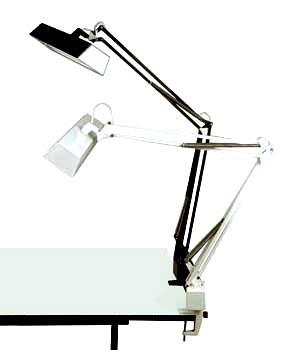
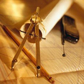
8 Instrument drawing Instruments are used to draw straight lines, circles, and curves concisely and accurately. Thus, the drawings are usually made to scale. Example


9 Computer drawing The drawings are usually made by commercial software such as AutoCAD, solid works etc. Example


10 CAD Software Popular CAD programs include AutoCAD, Inventor, SolidWorks, and ProE.
11 Applications Architects and Architectural engineers
12 Applications Mechanical, Aeronautical or Aerospace engineers
13 Civil engineers, Applications

14 Electrical engineers Applications
15 Pipeline engineers Applications
16 Engineering Drawing


17 Elements of Engineering Drawing Engineering drawing are made up of graphics language and word language. Graphics language Describe a shape (mainly). Word language Describe size, location and specification of the object.
18 Basic Knowledge for Drafting Graphics language Word language Line types Projection method Geometric construction Lettering


19 PROJECTION METHOD
20 PROJECTION METHOD Perspective Parallel Oblique Orthographic Axonometric Multiview
21 PROJECTION THEORY The projection theory is used to graphically represent 3-D objects on 2-D media (paper, computer screen). The projection theory is based on two variables: 1) Line of sight 2) Plane of projection (image plane or picture plane)
22 Line of sight is an imaginary ray of light between an observer s eye and an object. There are 2 types of LOS : parallel and converge Parallel projection Line of sight Perspective projection Line of sight
23 Plane of projection is an imaginary flat plane which the image is created. The image is produced by connecting the points where the LOS pierce the projection plane. Parallel projection Plane of projection Perspective projection Plane of projection
 It is difficult to create. 2) It does not reveal exact shape and size.")
24 Disadvantage of Perspective Projection Perspective projection is not used by engineer for manu- facturing of parts, because 1) It is difficult to create. 2) It does not reveal exact shape and size. Width is distorted


25 Orthographic Projection
26 MEANING Orthographic projection is a parallel projection technique in which the parallel lines of sight are perpendicular to the projection plane 1 Object views from top Projection plane
27 ORTHOGRAPHIC VIEW Orthographic view depends on relative position of the object to the line of sight. Two dimensions of an object is shown. More than one view is needed to represent the object. Rotate Tilt Multiview drawing Three dimensions of an object is shown. Axonometric drawing
28 NOTES ORTHOGRAPHIC VIEW Orthographic projection technique can produce either 1. Multiview drawing that each view show an object in two dimensions. 2. Axonometric drawing that show all three dimensions of an object in one view. Both drawing types are used in technical drawing for communication.


29 Axonometric (Isometric) Drawing Advantage Disadvantage Easy to understand Shape and angle distortion Example Distortions of shape and size in isometric drawing Circular hole becomes ellipse. Right angle becomes obtuse angle.

30 Multiview Drawing Advantage It represents accurate shape and size. Disadvantage Require practice in writing and reading. Example Multiviews drawing (2-view drawing)


31 Drawing Standard
32 Introduction Standards are set of rules that govern how technical drawings are represented. Drawing standards are used so that drawings convey the same meaning to everyone who reads them.
33 Standard Code Country Code Full name USA Japan UK Australia Germany ANSI JIS BS AS DIN ISO American National Standard Institute Japanese Industrial Standard British Standard Australian Standard Deutsches Institut für Normung International Standards Organization
34 Partial List of Drawing Standards Code number JIS Z 8311 JIS Z 8312 JIS Z 8313 JIS Z 8314 JIS Z 8315 JIS Z 8316 JIS Z 8317 Contents Sizes and Format of Drawings Line Conventions Lettering Scales Projection methods Presentation of Views and Sections Dimensioning
35 Drawing Sheet Trimmed paper of a size A0 ~ A4. Standard sheet size (JIS) A4 210 x 297 A3 297 x 420 A2 420 x 594 A1 594 x 841 A0 841 x 1189 (Dimensions in millimeters) A4 A3 A2 A1 A0
36 c c Orientation of drawing sheet 1. Type X (A0~A4) 2. Type Y (A4 only) d Border lines d Drawing space c Title block Drawing space Title block Sheet size c (mm) d (mm) A A A A A
37 Drawing Scales Length, size Scale is the ratio of the linear dimension of an element of an object shown in the drawing to the real linear dimension of the same element of the object. Size in drawing Actual size :

38 Why use a scale? In real world the object is large But we want to put it on a small piece of paper Or conversely: In real world the object is small But we want it to show up on a standard piece of paper
39 Drawing Scales All scales compare (PAPER SIZE) to (WORLD SIZE) Designation of a scale consists of the word SCALE followed by the indication of its ratio, as follow SCALE 1:1 for full size SCALE X:1 for enlargement scales (X > 1) SCALE 1:X for reduction scales (X > 1) - 1: 50 means one unit on the paper represents 50 unit on the actual object. - 50: 1 means 50 unit on the paper represents 1 unit on the actual object. Dimension numbers shown in the drawing are correspond to true size of the object and they are independent of the scale used in creating that drawing.
40 Choosing Unit and Scale Choosing a scale: Discipline standards Common usage Common sense Ratios whole numbers best --- 1:1, 1:2, 1:4, 1:8, 1:50, 1:200, or 4:1, 10:1 not --- 1:13, 1:46, 1:183 or 62:1 never --- use 1:4.54, 1:62.3, 1:112.9 Choose the correct units: Work in inches, mm, feet-yards or whatever is the natural measure for your drawing. The scale and the units are required to be indicated on the drawing.
41 Basic Line Types Types of Lines Continuous thick line Continuous thin line Dash thick line Chain thin line Appearance Name according to application Visible line Dimension line Extension line Leader line Hidden line Center line NOTE : We will learn other types of line in later chapters.
42 Meaning of Lines Visible lines represent features that can be seen in the current view Hidden lines represent features that can not be seen in the current view Center line represents symmetry, path of motion, centers of circles, axis of axisymmetrical parts Dimension and Extension lines indicate the sizes and location of features on a drawing


43 Example : Line conventions in engineering drawing
44 More on Center lines: Important for interpreting cylindrical shapes. Crossed center lines should be drawn at the centers of circles. They are also used to indicate paths of motion.


45 Traditional Drawing Tools


46 DRAWING TOOLS 1. DRAFTING BOARD


47 DRAWING TOOLS 2. T-Square 3. Triangles 30º, 60º, 45º


48 DRAWING TOOLS 4. PROTRACTOR Shape is a circle and semi circle 5. FRENCH CURVE


49 DRAWING TOOLS 2H or HB for thick line 4H for thin line 6. Adhesive Tape 7. Pencils


50 DRAWING TOOLS 8. Compass 9. BEAM COMPASS


51 DRAWING TOOLS 10. Pencil Eraser 11. Drafting Brush 12. Erasing Shield


52 DRAWING TOOLS 13. Circle Template 14. Ellipse Template


53 DRAWING TOOLS 15. Sharpener 16. Clean paper

54 Paper 17. Grid paper primarily used for drawing one-view sketches and orthographic views. Grid lines are uniformly spaced. 18. Isometric paper has evenly spaced lines running in three directions.
55 ABCDEFGHIJKLMNOPQRST UVWXYZABCDEFGHIJKLM NOPQRSTUVWXYZABCDEF Lettering ABCDEFGHIJKLMNOPQRST UVWXYZABCDEFGHIJKLM NOPQRSTUVWXYZABCDEF
56 Text on Drawings Text on engineering drawing is used : To communicate nongraphic information. As a substitute for graphic information, in those instance where text can communicate the needed information more clearly and quickly. Thus, it must be written with Legibility Uniformity - shape - space between letters and words - size - line thickness
57 Example Placement of the text on drawing Dimension & Notes Notes Title Block
58 Lettering Standard ANSI Standard Use a Gothic text style, either inclined or vertical. Use all capital letters. Use 3 mm for most text height. Space between lines of text is at least 1/3 of text height. This course Use only a vertical Gothic text style. Use both capital and lower-case letters. Same. For letters in title block it is recommend to use 5~8 mm text height N/A. Follows ANSI rule.

59 Basic Strokes Straight Slanted Horizontal Curved Examples : Application of basic stroke I letter A letter B letter

60 Upper-case letters & Numerals Straight line letters Suggested Strokes Sequence Curved line letters Curved line letters & Numerals

61 Lower-case letters Suggested Strokes Sequence The text s body height is about 2/3 the height of a capital letter.
62 Stroke Sequence I L T F E H
63 Stroke Sequence V X W
64 Stroke Sequence N M K Z Y A 4
65 Stroke Sequence O Q C G
66 Stroke Sequence D U P B R J 1 2
67 Stroke Sequence 5 7
68 Stroke Sequence S
69 Stroke Sequence l i
70 Stroke Sequence v w x k z
71 Stroke Sequence j y f t r
72 Stroke Sequence c o a b d p q e
73 Stroke Sequence g n m h u s
74 Word Composition Look at the same word having different spacing between letters. A) Non-uniform spacing JIRAPONG B) Uniform spacing J I R A P O N G Which one is easier to read?
75 Word Composition JIRAPONG Spacing Contour \/ \ )( ) ( General conclusions are: Space between the letters depends on the contour of the letters at an adjacent side. Good spacing creates approximately equal background area between letters.
76 Space between Letters 1. Straight - Straight 3. Straight - Slant 2. Straight - Curve 4. Curve - Curve
77 Space between Letters 5. Curve - Slant 6. Slant - Slant 7. The letter L and T slant slant straight slant


78 Example : Good and Poor Lettering GOOD Not uniform in style. Not uniform in height. Not uniformly vertical or inclined. Not uniform in thickness of stroke. Area between letters not uniform. Area between words not uniform.
79 Sentence Composition Leave the space between words equal to the space requires for writing a letter O. Example ALL O DIMENSIONS O ARE O IN MILLIMETERS OTHERWISE O UNLESS O SPECIFIED.

80 Freehand Sketching
81 Straight Line 1. Hold the pencil naturally. 2. Spot the beginning and end points. 3. Swing the pencil back and forth between the points, barely touching the paper until the direction is clearly established. 4. Draw the line firmly with a free and easy wrist-and-arm motion
82 Horizontal line Vertical line


83 Nearly vertical inclined line Nearly horizontal inclined line


84 Small Circle Method 1 : Starting with a square 1. Lightly sketching the square and marking the mid-points. 2. Draw light diagonals and mark the estimated radius. 3. Draw the circle through the eight points. Step 1 Step 2 Step 3


85 Small Circle Method 2 : Starting with center line 1. Lightly draw a center line. 2. Add light radial lines and mark the estimated radius. 3. Sketch the full circle. Step 1 Step 2 Step 3
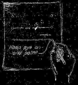
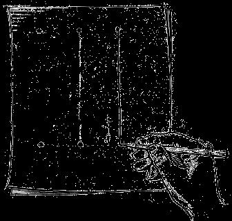
86 Large Circle 1. Place the little finger (or pencil s tip) at the center as a pivot, and set the pencil point at the radius-distance from the center. 2. Hold the hand in this position and rotate the paper.


87 Arc Method 1 : Starting with a square Method 2 : Starting with a center line
88 Steps in Sketching 1. Block in main shape. 2. Locate the features. 3. Sketch arcs and circles. 4. Sketch lines.
89 Example
Chapter 1 Overview of a Technical Drawing
 Chapter 1 Overview of a Technical Drawing TOPICS Graphics language Engineering drawing Projection methods Orthographic projection Drawing standards TOPICS Traditional Drawing Tools Lettering Dimensioning
CHAPTER 01 PRESENTATION OF TECHNICAL DRAWING. Prepared by: Sio Sreymean
 CHAPTER 01 PRESENTATION OF TECHNICAL DRAWING Prepared by: Sio Sreymean 2015-2016 Why do we need to study this subject? Effectiveness of Graphics Language 1. Try to write a description of this object. 2.
Chapter 1 Introduction
 Chapter 1 Introduction Contents Engineering drawing Drawing standards Drawing sheet Scale Lettering Line types Engineering Drawing Contents Engineering Drawing Effectiveness of Graphic Language 1. Try
Chapter 5 Pictorial Projection
 Chapter 5 Pictorial Projection Objectives After completing this chapter, the students will be able to Create freehand sketches using the correct sketching techniques. Explainthe difference between axonometric
Orthographic Projection
 Orthographic Projection Why Orthographic Projection is used in technical drawing Orthographic projection is a method of producing a number of separate two-dimensional inter-related views, which are mutually
Engineering Drawing Lecture 5 PROJECTION THEORY
 University of Palestine College of Engineering & Urban Planning First Level Engineering Drawing Lecture 5 PROJECTION THEORY Lecturer: Eng. Eman Al.Swaity Eng.Heba hamad PART 1 PROJECTION METHOD TOPICS
Copyrighted Material. Copyrighted Material. Copyrighted. Copyrighted. Material
 Engineering Graphics ORTHOGRAPHIC PROJECTION People who work with drawings develop the ability to look at lines on paper or on a computer screen and "see" the shapes of the objects the lines represent.
Student Name: Teacher: Date: District: Rowan. Assessment: 9_12 T and I IC61 - Drafting I Test 1. Description: Unit C - Sketching - Test 2.
 Student Name: Teacher: Date: District: Rowan Assessment: 9_12 T and I IC61 - Drafting I Test 1 Description: Unit C - Sketching - Test 2 Form: 501 1. The most often used combination of views includes the:
11/12/2015 CHAPTER 7. Axonometric Drawings (cont.) Axonometric Drawings (cont.) Isometric Projections (cont.) 1) Axonometric Drawings
 Axonometric Drawings (cont.) Isometric Projections (cont.) 1) Axonometric Drawings") CHAPTER 7 1) Axonometric Drawings 1) Introduction Isometric & Oblique Projection Axonometric projection is a parallel projection technique used to create a pictorial drawing of an object by rotating the
CHAPTER 7 1) Axonometric Drawings 1) Introduction Isometric & Oblique Projection Axonometric projection is a parallel projection technique used to create a pictorial drawing of an object by rotating the
Beginning Engineering Graphics 3 rd Week Lecture Notes Instructor: Edward N. Locke Topic: The Coordinate System, Types of Drawings and Orthographic
 Beginning Engineering Graphics 3 rd Week Lecture Notes Instructor: Edward N. Locke Topic: The Coordinate System, Types of Drawings and Orthographic 1 st Subject: The Cartesian Coordinate System The Cartesian
Chapter 5 Pictorial sketching
 Chapter 5 Pictorial sketching Contents Freehand sketching techniques Pictorial projections - Axonometric - Oblique Isometric projection vs isometric sketch Isometric sketch from an orthographic views Isometric
CE 100 Civil Engineering Drawing Sessional (Lab Manual)
") CE 100 Civil Engineering Drawing Sessional (Lab Manual) Department of Civil Engineering Ahsanullah University of Science and Technology November, 2017 1 Preface This course is designed to provide civil
CE 100 Civil Engineering Drawing Sessional (Lab Manual) Department of Civil Engineering Ahsanullah University of Science and Technology November, 2017 1 Preface This course is designed to provide civil
Multiviews and Auxiliary Views
 Multiviews and Auxiliary Views Multiviews and Auxiliary Views Objectives Explain orthographic and multiview projection. Identifying the six principal views. Apply standard line practices to multiviews
Engineering Graphics. Class 2 Drafting Instruments Mohammad Kilani
 Engineering Graphics Class 2 Drafting Instruments Mohammad Kilani Drafting Instruments A Design is as good as its instruments A engineering drawing is a highly stylized graphic representation of an idea.
Multiview Drawing. Definition: Graphical representation of a 3- dimensional object on one plane (sheet of paper) using two or more views.
 using two or more views.") Multiview Drawing Definition: Graphical representation of a 3- dimensional object on one plane (sheet of paper) using two or more views. Multiview Drawing Another name for multiview drawing is orthographic
Multiview Drawing Definition: Graphical representation of a 3- dimensional object on one plane (sheet of paper) using two or more views. Multiview Drawing Another name for multiview drawing is orthographic
UNIT 5a STANDARD ORTHOGRAPHIC VIEW DRAWINGS
 UNIT 5a STANDARD ORTHOGRAPHIC VIEW DRAWINGS 5.1 Introduction Orthographic views are 2D images of a 3D object obtained by viewing it from different orthogonal directions. Six principal views are possible
(As per New Revised Syllabus of Anna University) Department of Mechanical Engineering. SATHYABAMA UNIVERSITY Jeppiaar Nagar, Chennai
 Department of Mechanical Engineering. SATHYABAMA UNIVERSITY Jeppiaar Nagar, Chennai") (1*,1((5,1* *5$3+,&6 (As per New Revised Syllabus of Anna University) Dr. S.RAMACHANDRAN, M.E., Ph.D. Professor & Head K. PANDIAN, M.E., E.V.V.RAMANAMURTHY, M.Tech., R. DEVARAJ, M.E., Associate Professors
(1*,1((5,1* *5$3+,&6 (As per New Revised Syllabus of Anna University) Dr. S.RAMACHANDRAN, M.E., Ph.D. Professor & Head K. PANDIAN, M.E., E.V.V.RAMANAMURTHY, M.Tech., R. DEVARAJ, M.E., Associate Professors
AutoCAD 2D-I. Module 1: Introduction to Drawing Tools. IAT Curriculum Unit PREPARED BY. January 2011
 AutoCAD 2D-I Module 1: Introduction to Drawing Tools PREPARED BY IAT Curriculum Unit January 2011 Institute of Applied Technology, 2011 Module 1: Introduction to Drawing Tools Module Objectives After
ORTHOGRAPHIC PROJECTION
 ORTHOGRAPHIC PROJECTION C H A P T E R S I X OBJECTIVES 1. Recognize and the symbol for third-angle projection. 2. List the six principal views of projection. 3. Understand which views show depth in a drawing
ORTHOGRAPHIC PROJECTIONS. Ms. Sicola
 ORTHOGRAPHIC PROJECTIONS Ms. Sicola Objectives List the six principal views of projection Sketch the top, front and right-side views of an object with normal, inclined, and oblique surfaces Objectives
Brief Introduction to Engineering Graphics The use of drawings to convey information. Sketching freehand straight edge
 Brief Introduction to Engineering Graphics The use of drawings to convey information. Sketching freehand straight edge CAD drawings 2D drafting 3D model to 2D drawings 1 Different Graphical Representation
Isometric Drawing Chapter 26
 Isometric Drawing Chapter 26 Sacramento City College EDT 310 EDT 310 - Chapter 26 - Isometric Drawing 1 Drawing Types Pictorial Drawing types: Perspective Orthographic Isometric Oblique Pictorial - like
CLASS views from detail on a grid paper. (use appropriate line types to show features) - Optional views. Turn in for grading on class 6 (06/04)
 - Optional views. Turn in for grading on class 6 (06/04)") CLASS 4 Review: - Projections - Orthographic projections Lab: - 3 views from detail on a grid paper. (use appropriate line types to show features) - Optional views. Turn in for grading on class 6 (06/04)
CLASS 4 Review: - Projections - Orthographic projections Lab: - 3 views from detail on a grid paper. (use appropriate line types to show features) - Optional views. Turn in for grading on class 6 (06/04)
ENGINEERING DRAWING. 1. Set squares are used to draw different angles. What is the angel a formed by the 45⁰ set square? Give a brief answer.
 ENGINEERING DRAWING 1. Set squares are used to draw different angles. What is the angel a formed by the 45⁰ set square? Give a brief answer. 2. Which is the correct method of hatching a plane surface?
Engineering Graphics- Basics.
 Engineering Graphics- Basics DRAWINGS: ( A Graphical Representation) The Fact about: If compared with Verbal or Written Description, Drawings offer far better idea about the Shape, Size & Appearance of
Technological Design Mr. Wadowski. Orthographic & Isometric Drawing Lesson
 Technological Design Mr. Wadowski Orthographic & Isometric Drawing Lesson TOPICS Working Drawings, Isometric Drawings & Orthographic Drawings Glass box concept Multiview projection Orthographic projection
technical drawing
 technical drawing school of art, design and architecture nust spring 2011 http://www.youtube.com/watch?v=q6mk9hpxwvo http://www.youtube.com/watch?v=bnu2gb7w4qs Objective abstraction - axonometric view
Drawing sheet: - The various size of the drawing sheet used for engineering drawing as per IS Are listed in the table
 Dronacharya Group of Institutions, Greater Noida Computer Aided Engineering Graphics (CAEG) (NCE 151/251) List of Drawing Sheets: 1. Letter writing & Dimensioning. 2. Projection of Points & Lines. 3. Projection
PROJECTIONS PARALLEL CONICAL PROJECTIONS PROJECTIONS OBLIQUE ORTHOGRAPHIC PROJECTIONS PROJECTIONS
 PROJECTIONS CONICAL PROJECTIONS PARALLEL PROJECTIONS OBLIQUE PROJECTIONS ORTHOGRAPHIC PROJECTIONS ISOMETRIC MULTI-VIEW an object; The Description of Forms Behind every drawing of an object is space relationship
Multi-View Drawing Review
 Multi-View Drawing Review Sacramento City College EDT 300/ENGR 306 EDT 300 / ENGR 306 - Chapter 5 1 Objectives Identify and select the various views of an object. Determine the number of views needed to
MISS. HANNA S CLASSROOM RULES
 MISS. HANNA S CLASSROOM RULES 1. My students never fail. I believe in you and so shall you! Miss. Hanna s Quote! 2. Come to class on time. 3. Bring a positive attitude. 4. Come prepared and bring your
Production drawing Diagram. a) I am a freehand drawing that follows technical drawing standards.
 I am a freehand drawing that follows technical drawing standards.") THE TECHNOLOGICAL WORLD Graphical language STUDENT BOOK Ch. 11, pp. 336 342 Basic lines, geometric lines, sketches 1. In technology, the two most widely used types of technical drawings are: a) sketch
THE TECHNOLOGICAL WORLD Graphical language STUDENT BOOK Ch. 11, pp. 336 342 Basic lines, geometric lines, sketches 1. In technology, the two most widely used types of technical drawings are: a) sketch
DMT113 Engineering Drawing. Chapter 3 Stretch System
 DMT113 Engineering Drawing Chapter 3 Stretch System Contents Theory & Multiview Planes 6 Principle Views Multiview Sketching Technique & Perspective First & Third Angle Multiview Representations Theory
Pictorial Drawings. DFTG-1305 Technical Drafting Prepared by Francis Ha, Instructor
 DFTG-1305 Technical Drafting Prepared by Francis Ha, Instructor Pictorial Drawings Geisecke s textbook for reference: 14 th Ed. Ch. 15: p. 601 Ch. 16: p. 620 15 th Ed. Ch. 14: p. 518 Ch. 15: p. 552 Update:
Mechanical Drawing. Unit 2 Study Guide for Chapters 6-10
 Mechanical Drawing Unit 2 Study Guide for Chapters 6-10 Chapter 6 Multiview Drawing Section 6.1 Understanding Orthographic Projection A. Technical Drawing: How can a technical drawing give more accurate
Engineering Graphics Essentials with AutoCAD 2015 Instruction
 Kirstie Plantenberg Engineering Graphics Essentials with AutoCAD 2015 Instruction Text and Video Instruction Multimedia Disc SDC P U B L I C AT I O N S Better Textbooks. Lower Prices. www.sdcpublications.com
Glass Box Projection. Gives you 6 sides to view of an object. 10/2/14 2
 2D Drawings Glass Box Projection Gives you 6 sides to view of an object. 10/2/14 2 We can simplify this for some objects to 3 views Glass Box Approach Glass Box Approach Glass Box Approach Glass Box Approach
ENGINEERING GRAPHICS 1.0 Introduction Engineering Graphics Drawing as an art Artist Graphic design Engineering graphics engineering drawing
 ENGINEERING GRAPHICS 1.0 Introduction Engineering is the profession in which the knowledge of mathematics and science gained by study, experience and practice is applied with good judgment to develop a
Chapter 8. Technical Drawings
 Chapter 8 Technical Drawing Technical Drawings Multiview drawings Also called three-view drawings Simple objects take three views Front, top, one side Title block Identifies who did the design Gives date,
ENGINEERING GRAPHICS ESSENTIALS
 ENGINEERING GRAPHICS ESSENTIALS with AutoCAD 2012 Instruction Introduction to AutoCAD Engineering Graphics Principles Hand Sketching Text and Independent Learning CD Independent Learning CD: A Comprehensive
60 Most Important Engineering Drawing Questions
 1. If a client of yours is having difficulty visualizing a design, what type of drawing would be the easiest to understand? A. axonometric B. three-view orthographic C. one-view orthographic D. bimetric
1: Assemblage & Hierarchy
 What: 1: Assemblage & Hierarchy 2 compositional sequences o abstract, line compositions based on a 9 square grid o one symmetrical o one asymmetrical Step 1: Collage Step 2: Additional lines Step 3: Hierarchy
Civil Engineering Drawing
 Civil Engineering Drawing Third Angle Projection In third angle projection, front view is always drawn at the bottom, top view just above the front view, and end view, is drawn on that side of the front
Graphical Communication
 Chapter 9 Graphical Communication mmm Becoming a fully competent engineer is a long yet rewarding process that requires the acquisition of many diverse skills and a wide body of knowledge. Learning most
2. Line composed of closely and evenly spaced short dashes in a drawing represents
 1. Hidden lines are drawn as (a) dashed narrow lines (b) dashed wide lines (c) long-dashed dotted wide line (d) long-dashed double dotted wide line Ans: (a) 2. Line composed of closely and evenly spaced
2010 Academic Challenge
 2010 Academic Challenge ENGINEERING GRAPHICS TEST STATE FINALS This Test Consists of 40 Questions Engineering Graphics Test Production Team Ryan K. Brown, Illinois State University Author/Team Leader Jacob
A Concise Introduction to Engineering Graphics
 A Concise Introduction to Engineering Graphics Fourth Edition Including Worksheet Series A Timothy J. Sexton, Professor Department of Industrial Technology Ohio University BONUS Book on CD: TECHNICAL GRAPHICS
ENGINEERING GRAPHICS 1E9
 Lecture 3 Monday, 15 December 2014 1 ENGINEERING GRAPHICS 1E9 Lecture 3: Isometric Projections Lecture 3 Monday, 15 December 2014 2 What is ISOMETRIC? It is a method of producing pictorial view of an object
Technical Drawing 101 with AutoCAD 2018
 Technical Drawing 101 with AutoCAD 2018 A Multidisciplinary Guide to Drafting Theory and Practice with Video Instruction Douglas Smith Antonio Ramirez Ashleigh Fuller SDC PUBLICATIONS Better Textbooks.
Engineering Working Drawings Basics
 Engineering Working Drawings Basics Engineering graphics is an effective way of communicating technical ideas and it is an essential tool in engineering design where most of the design process is graphically
Sketching in SciTech. What you need to know for graphic communication
 Sketching in SciTech What you need to know for graphic communication Sketching in your Logbook Use pencil Take up the WHOLE PAGE Label things 1. Proportion Each part of the sketch is the right size,
2004 Academic Challenge
 2004 Academic Challenge ENGINEERING GRAPHICS TEST - REGIONAL Engineering Graphics Test Production Team Ryan Brown, Illinois State University Author/Team Coordinator Kevin Devine, Illinois State University
Chapter 6. Architectural Lines and Lettering
 Chapter 6 Architectural Lines and Lettering Drafting Introduction Universal graphic language Uses lines, symbols, dimensions, and notes to describe a structure to be built Properly drawn lines are dark,
MULTIPLE CHOICE QUESTIONS - CHAPTER 6
 MULTIPLE CHOICE QUESTIONS - CHAPTER 6 1. The selection of the front view in executing a multiview drawing of an object is dependent upon the following factors: a. size and shape of the object and their
GE ENGINEERING GRAPHICS
 ANNA UNIVERSITY, CHENNAI (REGULATION GE8152 - ENGINEERING GRAPHICS B.E SEMESTER I Lecture Tutorial Practical Marks Credits Total Hours 2 0 3 100 4 90 Mr.S.Gokul (Asst. Prof/Mech) Sri Eshwar College of
1 st Subject: 2D Geometric Shape Construction and Division
 Joint Beginning and Intermediate Engineering Graphics 2 nd Week 1st Meeting Lecture Notes Instructor: Edward N. Locke Topic: Geometric Construction 1 st Subject: 2D Geometric Shape Construction and Division
(Ans:d) a. A0 b. A1 c. A2 d. A3. (Ans:b) (Ans:a) (Ans:d) (Ans:d)
 a. A0 b. A1 c. A2 d. A3. (Ans:b) (Ans:a) (Ans:d) (Ans:d)") Multiple Choice Questions (MCQ) on Engineering Drawing (Instruments) The mini drafter serves the purpose of everything except a. Scales b. Set square c. Protractor d. Compass (Ans:d) During operation,
Multiple Choice Questions (MCQ) on Engineering Drawing (Instruments) The mini drafter serves the purpose of everything except a. Scales b. Set square c. Protractor d. Compass (Ans:d) During operation,
TECHNICAL DESIGN I (540)
") DESCRIPTION The first assessment in a series, Technical Design I prepares students to develop technical knowledge and skills required to plan and prepare scale pictorial interpretations of engineering
DESCRIPTION The first assessment in a series, Technical Design I prepares students to develop technical knowledge and skills required to plan and prepare scale pictorial interpretations of engineering
Activity 5.2 Making Sketches in CAD
 Activity 5.2 Making Sketches in CAD Introduction It would be great if computer systems were advanced enough to take a mental image of an object, such as the thought of a sports car, and instantly generate
Technical Graphics Higher Level
 Coimisiún na Scrúduithe Stáit State Examinations Commission Junior Certificate Examination 2005 Technical Graphics Higher Level Marking Scheme Sections A and B Section A Q1. 12 Four diagrams, 3 marks for
Orthographic Drawing (Architectural Board Drafting)
") Design and Drafting Description In this activity, the teacher will introduce orthographic projection, in which a multi-view drawing shows how the sides of an object are related to each another. Students
Design and Drafting Description In this activity, the teacher will introduce orthographic projection, in which a multi-view drawing shows how the sides of an object are related to each another. Students
Chapter 2: Dimensioning Basic Topics Advanced Topics Exercises
 Chapter 2: Dimensioning Basic Topics Advanced Topics Exercises Dimensioning: Basic Topics Summary 2-1) Detailed Drawings 2-2) Learning to Dimension 2-3) Dimension Appearance and Techniques. 2-4) Dimensioning
2003 Academic Challenge
 Worldwide Youth in Science and Engineering 2003 Academic Challenge ENGINEERING GRAPHICS TEST - REGIONAL Engineering Graphics Test Production Team Ryan Brown, Illinois State University Author/Team Coordinator
CAD Mechanical Design I
 EXAM INFORMATION Items 58 Points 85 Prerequisites NONE Course Length ONE SEMESTER Career Cluster ARCHITECTURE AND CONSTRUCTION MANUFACTURING SCIENCE, TECHNOLOGY, ENGINEERING AND MATHEMATICS Performance
ME1105 Engineering Drawing & Design
 City University London Term 1 Assessment 2008/2009 School of Engineering and Mathematical Sciences ME1105 Engineering Drawing & Design Student Name:.., Group: Examination duration: Reading time: This paper
1 ISOMETRIC PROJECTION SECTION I: INTRODUCTION TO ISOMETRIC PROJECTION
 1 ISOMETRIC PROJECTION SECTION I: INTRODUCTION TO ISOMETRIC PROJECTION Orthographic projection shows drawings of an object in a two-dimensional format, with views given in plan, elevation and end elevation
ME 111: Engineering Drawing
 ME 111: Engineering Drawing Lecture # 01 Introduction For more detail, visit http://shilloi.iitg.ernet.in/~psr/ Indian Institute of Technology Guwahati Guwahati 781039 1 Syllabus 1. Importance of engineering
Interpretation of Drawings. An Introduction to the Basic Concepts of Creating Technical Drawings
 Interpretation of Drawings An Introduction to the Basic Concepts of Creating Technical Drawings Introduction In the design process drawings are the main way in which information about an object or product
DFTG 1305 UNIT 1. Semester: Spring 2016 Class #: Term: SS Instructor: Mays ALSabbagh
 DFTG 1305 UNIT 1 Semester: Spring 2016 Class #: 94412 Term: SS Instructor: Mays ALSabbagh Technical Drafting Unit One: Introduction to Drafting Chapter 1 : The World Wide Graphic language for Design Lecture
Two-Dimensional Drawing
 22 Chapter Cxxxx 40757 3/19/08 10:24 AM Page 1 7% 3% 3% 18% 20% 22 Chapter CXXXX 40757 Page 1 03/18/08 MD 22 Two-Dimensional Drawing objectives After completing this chapter, you should be able to Identify
Drawing: technical drawing TECHNOLOGY
 Drawing: technical drawing Introduction Humans have always used images to communicate. Cave paintings, some of which are over 40,000 years old, are the earliest example of this artistic form of communication.
ENGINEERING GRAPHICS ESSENTIALS
 ENGINEERING GRAPHICS ESSENTIALS Text and Digital Learning KIRSTIE PLANTENBERG FIFTH EDITION SDC P U B L I C AT I O N S Better Textbooks. Lower Prices. www.sdcpublications.com ACCESS CODE UNIQUE CODE INSIDE
3D Viewing I. Acknowledgement: Some slides are from the Dr. Andries van Dam lecture. CMSC 435/634 August D Viewing I # /27
 3D Viewing I Acknowledgement: Some slides are from the Dr. Andries van Dam lecture. From 3D to 2D: Orthographic and Perspective Projection Part 1 Geometrical Constructions Types of Projection Projection
Unit 4: Geometric Construction (Chapter4: Geometry For Modeling and Design)
") Unit 4: Geometric Construction (Chapter4: Geometry For Modeling and Design) DFTG-1305 Technical Drafting Instructor: Jimmy Nhan OBJECTIVES 1. Identify and specify basic geometric elements and primitive
Unit 4: Geometric Construction (Chapter4: Geometry For Modeling and Design) DFTG-1305 Technical Drafting Instructor: Jimmy Nhan OBJECTIVES 1. Identify and specify basic geometric elements and primitive
Sketching Fundamentals
 Sketching Fundamentals Learning Outcome When you complete this module you will be able to: Make basic engineering sketches of plant equipment. Learning Objectives Here is what you will be able to do when
Multiview Projection
 DFTG-1305 Technical Drafting Prof. Francis Ha Session 4 Multiview Projection (or Orthographic Projection) Reading: Geisecke s textbook: 14 th Ed. Chapter 5 p.162 15 th Ed. Chapter 6 p.232 Update: 17-0510
PELLISSIPPI STATE TECHNICAL COMMUNITY COLLEGE MASTER SYLLABUS. FUNDAMENTALS OF TECHNICAL DRAWING W/LAB CID 1100 (formerly CID 1104)
") PELLISSIPPI STATE TECHNICAL COMMUNITY COLLEGE MASTER SYLLABUS FUNDAMENTALS OF TECHNICAL DRAWING W/LAB CID 1100 (formerly CID 1104) Class Hours: 3.0 Credit Hours: 3.0 Laboratory Hours: 3.0 Revised: Spring
PELLISSIPPI STATE TECHNICAL COMMUNITY COLLEGE MASTER SYLLABUS FUNDAMENTALS OF TECHNICAL DRAWING W/LAB CID 1100 (formerly CID 1104) Class Hours: 3.0 Credit Hours: 3.0 Laboratory Hours: 3.0 Revised: Spring
DELHI TECHNOLOGICAL UNIVERSITY ENGINEERING GRAPHICS LAB MANUAL
 DELHI TECHNOLOGICAL UNIVERSITY ENGINEERING GRAPHICS LAB MANUAL NAME: - ROLL NO: - GROUP: - BRANCH: - GROUP TEACHER: Page 1 www.rooplalrana.com 1 GENERAL INSTRUCTIONS FOR ENGG. GRAPHICS LAB 1) Students
ENGINEERING DRAWING SKKK 1021 ISOMETRIC DRAWING. Agus Arsad, Azizul Azri Bin Mustaffa 10/2/2012 1
 ENGINEERING DRAWING SKKK 1021 ISOMETRIC DRAWING Agus Arsad, Azizul Azri Bin Mustaffa 10/2/2012 1 LEARNING OUTCOMES ISOMETRIC DRAWING It is expected that students will be able to: Understand the significance
ENGINEERING GRAPHICS ESSENTIALS. (A Text and Lecture Aid) Second Edition. Kirstie Plantenberg University of Detroit Mercy SDC PUBLICATIONS
 Second Edition. Kirstie Plantenberg University of Detroit Mercy SDC PUBLICATIONS") ENGINEERING GRAPHICS ESSENTIALS (A Text and Lecture Aid) Second Edition Kirstie Plantenberg University of Detroit Mercy SDC PUBLICATIONS Schroff Development Corporation www.schroff.com www.schroff-europe.com
ENGINEERING GRAPHICS ESSENTIALS (A Text and Lecture Aid) Second Edition Kirstie Plantenberg University of Detroit Mercy SDC PUBLICATIONS Schroff Development Corporation www.schroff.com www.schroff-europe.com
Philadelphia University Faculty of Engineering Mechanical Engineering Department
 Philadelphia University Faculty of Engineering Mechanical Engineering Department Basics of Engineering Drawing Manual Done by:- Eng. Laith R.I. Batarseh Eng. Hanan Khamis 2017 1 Table of contents SUBJECT
Drafting Dictionary (Mechanical Board Drafting)
") Description In this lesson the teacher will introduce the tools and equipment specific to board drafting. Board drafting (also known as manual drafting) refers to precision drawing with specialized instruments.
Description In this lesson the teacher will introduce the tools and equipment specific to board drafting. Board drafting (also known as manual drafting) refers to precision drawing with specialized instruments.
ENGR 1182 Exam 1 First Mid Term Exam Study Guide and Practice Problems
 Spring Semester 2016 ENGR 1182 Exam 1 First Mid Term Exam Study Guide and Practice Problems Disclaimer Problems in this study guide resemble problems relating mainly to the pertinent homework assignments.
INTRODUCTION to CAD ACAD BASICS. 2.1 Starting with ACAD. 2.2 Layout and sketching. 2.3 Drawing environment. 2.4 Elements of drawing
 INTRODUCTION to CAD ACAD BASICS 2.1 Starting with ACAD 2.2 Layout and sketching 2.3 Drawing environment 2.4 Elements of drawing 2.4.1 Draw commands 2.5 3D functions 2.6 Starting the drawing 2.6.1 Drawing
2003 Academic Challenge
 Worldwide Youth in Science and Engineering 2003 Academic Challenge ENGINEERING GRAPHICS TEST - SECTIONAL Engineering Graphics Test Production Team Ryan Brown, Illinois State University Author/Team Coordinator
Isometric Projection Drawing CHAPTER 6
 Isometric Projection Drawing CHAPTER 6 Content Overview Pictorial projection Parallel projection Axonometric projection Isometric projection Axes and selection Isometric lines and planes Isometric scale
Fundamentals for building Drawing
 Fundamentals for building Drawing What is Drawing Introduction Knowledge of preparing and understanding drawing will prove to be an invaluable aid while performing their jobs effectively, efficiently.
MODELING AND DESIGN C H A P T E R F O U R
 MODELING AND DESIGN C H A P T E R F O U R OBJECTIVES 1. Identify and specify basic geometric elements and primitive shapes. 2. Select a 2D profile that best describes the shape of an object. 3. Identify
Reavis High School Curriculum Snapshot/Cover Page for Computer Aided Design (CAD)
") Reavis High School Curriculum Snapshot/Cover Page for Computer Aided Design (CAD) Unit 1: Introduction In this unit, students will identify components of a Computer Aided Design (CAD) system and how to
Reavis High School Curriculum Snapshot/Cover Page for Computer Aided Design (CAD) Unit 1: Introduction In this unit, students will identify components of a Computer Aided Design (CAD) system and how to
JUNIOR CERTIFICATE 2009 MARKING SCHEME TECHNICAL GRAPHICS HIGHER LEVEL
 . JUNIOR CERTIFICATE 2009 MARKING SCHEME TECHNICAL GRAPHICS HIGHER LEVEL Sections A and B Section A any ten questions from this section Q1 12 Four diagrams, 3 marks for each correct label. Q2 12 2 marks
Study Unit. Auxiliary Views. This sneak preview of your study material has been prepared in advance of the book's actual online release.
 Study Unit Auxiliary Views This sneak preview of your study material has been prepared in advance of the book's actual online release. iii Preview You re entering now into another subject area in your
ENGR 1182 Midterm Exam 1: Study Guide and Practice Problems
 ENGR 1182 Midterm Exam 1: Study Guide and Practice Problems Disclaimer Problems seen in this study guide may resemble problems relating mainly to the pertinent homework assignments. Reading this study
AutoCAD Tutor 2011 Support Docs
 AutoCAD Tutor 2011 Support Docs CHAPTER 1 CUSTOMIZING THE QUICK ACCESS TOOLBAR One of the advantages of the Quick Access Toolbar is the ability to display the AutoCAD commands that you frequently use.
Chapter 2 Using Drawing Tools & Applied Geometry
 Chapter 2 Using Drawing Tools & Applied Geometry TOPICS Preparation of Tools. Using of Tools Applied Geometry PREPARATION OF TOOLS Fastening Paper to Drafting Board 1. Place the paper close to the table
PELLISSIPPI STATE TECHNICAL COMMUNITY COLLEGE MASTER SYLLABUS ENGINEERING DRAWING W/LAB CID 1105
 PELLISSIPPI STATE TECHNICAL COMMUNITY COLLEGE MASTER SYLLABUS ENGINEERING DRAWING W/LAB CID 1105 Class Hours: 3.0 Credit Hours: 4.0 Laboratory Hours: 3.0 Revised: Spring 05 Catalog Course Description:
Student Name: Teacher: Date: District: Rowan. Assessment: 9_12 T and I IC61 - Drafting I Test 2. Description: Drafting 1 - Test 6.
 Student Name: Teacher: Date: District: Rowan Assessment: 9_12 T and I IC61 - Drafting I Test 2 Description: Drafting 1 - Test 6 Form: 501 1. 2X on a hole note means: A. Double the size of the hole. B.
DFTG-1305 Technical Drafting Prof. Francis Ha
 DFTG-1305 Technical Drafting Prof. Francis Ha Session 4 Orthographic Projection (or Multiview Projection) Reading: Geisecke s textbook: 14 th Ed. Chapter 5 p.162 15 th Ed. Chapter 6 p.232 Update: 18-0205
Isometric Drawing (Architectural Board drafting)
") Design and Drafting Description Isometric drawings use perspective to communicate a large amount of information in a single drawing. Isometric drawings show three sides of an object, making it easier to
Design and Drafting Description Isometric drawings use perspective to communicate a large amount of information in a single drawing. Isometric drawings show three sides of an object, making it easier to
Unit-5 ISOMETRIC PROJECTION
 Unit-5 ISOMETRIC PROJECTION Importance Points in Isometric: 1. For drawing the isometric, the object must be viewed such that either the front -right or the left edges becomes nearest. 2. All vertical
DFTG-1305 Technical Drafting Prof. Francis Ha
 DFTG-1305 Technical Drafting Prof. Francis Ha Session 5 Dimensioning Geisecke s textbook: 14 th Ed. Chapter 10 p. 362 15 th Ed. Chapter 11 p. 502 Update: 17-0508 Dimensioning Part 1 of 2 Dimensioning Summary