Pictorial Drawings. DFTG-1305 Technical Drafting Prepared by Francis Ha, Instructor
|
|
|
- Winifred Golden
- 5 years ago
- Views:
Transcription
1 DFTG-1305 Technical Drafting Prepared by Francis Ha, Instructor Pictorial Drawings Geisecke s textbook for reference: 14 th Ed. Ch. 15: p. 601 Ch. 16: p th Ed. Ch. 14: p. 518 Ch. 15: p. 552 Update:
2 Key points: They are used to aid visualization. A pictorial is a 2-D pseudo 3-D drawing. What will we learn in this Chapter? Pictorial Drawings How to create a pictorial drawing.
3 Contents Pictorials Introduction Isometric Pictorial Axes Oblique Pictorials Overview Drawing Linear Features Drawing Circles and Radii Drawing Cylinders
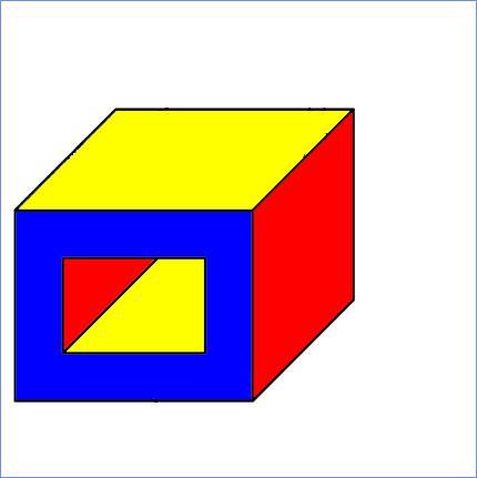
4 Draw an Isometric Drawn in 2-D. Looks like a 3-D.
5 Two types of pictorials: Isometric Oblique
6 Isometric Pictorial
7 Isometric Pictorial Axes Isometric pictorials are drawn in a coordinate system where the axes are 60 degrees apart.
8 Drawing Linear Features Step 1 - Draw the three construction lines that represent the isometric axes.
9 Isometric Pictorials Scale The linear features on, or parallel, to these three axes are drawn at between 50-80% (recommended) scale to represent true size. Isometric pictorials may be drawn at any scale (between 50%-80% normally) as long as the scale is uniform on all axes.
10 Isometric How do we draw an isometric pictorial?
11 Isometric How do we draw an isometric pictorial?
12 Isometric How do we draw an isometric pictorial?
13 Isometric How do we draw an isometric pictorial?
14 Isometric How do we draw an isometric pictorial?
15 Exercise1 Creating an Isometric Pictorial In-class Practice
16 Drawing Linear Features How do we draw an isometric pictorial?
17 Isometric Procedures Drawing Linear Features Step 1 - Draw a defining box (Side dimensions = the height, width and depth of the object)
18 Drawing Linear Features Step 2 Sketch the based lines a reduced scale, 80% isometric pictorial of the following object.
19 Drawing Linear Features Step 3 - Draw the lines of the object that are parallel to the axes.
20 Drawing Linear Features Step 4 - Add the lines of the object that are not parallel to one of the axes.
21 Drawing Linear Features Step 4 (cont.)- Add the lines of the object that are not parallel to one of the axes.
22 Drawing Linear Features Step 4 (cont.)- Add the lines of the object that are not parallel to one of the axes.
23 Drawing Linear Features Step 5 - Erase or remove the construction lines.

24 Drawing Linear Features Step 5 - Erase or remove the construction lines.
25 Oblique Pictorials
26 Oblique Pictorials In the oblique pictorials coordinate system, only one axis is at an angle. The angle may range between 1 and 89 degrees; however, the most commonly used angle is 45 degrees.
27 Oblique Pictorials The features drawn on the plane defined by the vertical and horizontal axes are drawn at full scale and true shape. The front view should be squared
28 Oblique Pictorials The linear features drawn on the angled axis may be full scale (cavalier projection) or may be drawn foreshortened. The most common, is half scale (cabinet projection).
29 Oblique Pictorials
30 Oblique Pictorials
31 Oblique How do we draw an oblique pictorial?
32 Oblique How do we draw an oblique pictorial?
33 Oblique How do we draw an oblique pictorial?

34 Oblique How do we draw an oblique pictorial?

35 Oblique How do we draw an oblique pictorial?

36 COMPARISON Oblique vs. Isometric What differences can you see?
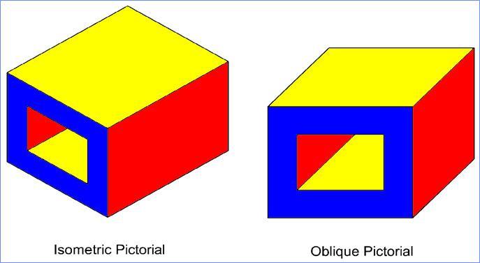
37 COMPARISON
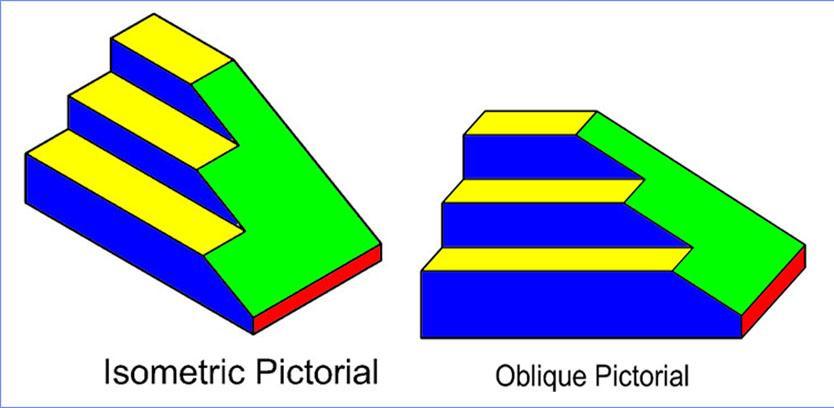
38 COMPARISON
39 How to draw Circles and Radii in pictorial?
40 How to draw an ellipse?
41 Drawing Isometric Circle and Radii Circular features of an object appear as ellipses on an isometric pictorial.
42 Drawing Circle and Radii Step 1: Draw the linear features of the object using the procedure previously described. Squares become rhombuses. Reduced scale to 50% isometric pictorial of the following object.
43 Drawing Circles and Radii Step 2: Draw diagonals and ellipses in boxes that define the beginning and end of the cylinder.
44 Drawing Circles and Radii Step 3: Draw an ellipse in the box whose major axis is aligned with the long diagonal of the box. The ellipses touch the box at the midpoint of its sides. The same procedure is used for creating radii except that the unwanted part of the ellipse is erased or trimmed. Major Axis

45 Drawing Circles and Radii Step 4: Erase or remove the construction lines Erase or remove the lines of behind cylinder.
46 How to Draw Cylinders
47 Drawing Cylinders Step 1: Draw a defining box and first ellipse a defining box. The height is equal to the height of the cylinder and the width and depth are equal to the diameter of the cylinder.
48 Drawing Cylinders Step 2: Draw diagonals and second ellipses a defining box. The height is equal to the height of the cylinder and the width and depth are equal to the diameter of the cylinder.
49 Drawing Cylinders Step 3: Draw diagonals and ellipses in boxes that define the beginning and end of the cylinder. Major Axis
50 Drawing Cylinders Step 4: Erase or remove the construction lines.
51 Drawing Cylinders Step 5: Erase or remove the lines of behind cylinder.

52 Drawing Cylinders Cylinders in an isometric pictorial is a drawing with two circles and adding some connecting lines.
53 Exercise 2 Creating an Isometric Pictorial In-class Practice
54 Step 1: Draw three construction lines that represent the isometric axes. The grid spacing is 0.25 inch.
55 To do: Create a reduced scale, say, 50% isometric pictorial of the following object (4 steps)
56 Step 2: Draw a box whose sides are parallel to the three axes and whose lengths are ½ (50%) the maximum height, width and depth dimension of the object.
57 Step 3: Draw the lines of the object that are parallel to the axes.
58 Step 4: The lines of the object that are not parallel to one of the axes are added by connecting the ends of existing lines.
59 Continue Step 4

60 Continue Step 4

61 Step 5: Erase or remove the construction lines. Done.
62 Exercise 3 Creating an Isometric Pictorial In-class Practice
63 Skip to next part of the exercise Exercise 2 Create a reduced scale, say, 50% isometric pictorial of the following object. The grid spacing is 10 mm.

64 Step 1: Draw the linear features of the object using the procedure previously described.

65 Step 2: Draw a box whose diagonals meet at the center of the radius and the length of the sides are equal to the 2R.

66 Step 3: Draw an ellipse in the box whose major axis is aligned with the long diagonal of the box. The ellipses touch the box at the midpoint of its sides.

67 Step 4: Repeat for the bottom radius.
68 Step 5: Use a vertical line to connect the ellipses.
69 Step 6: Erase half of ellipses.

70 Step 7: Draw the defining boxes for the cylindrical feature on the top of the part.

71 Step 8: Draw ellipses in the defining boxes for the cylindrical feature on the top of the part.

72 Step 9: Draw and connect the ellipses.

73 Step 10: Draw the ellipse that represents the thru hole.

74 Step 11: Draw the defining box and cylinder that defines the counterbore.

75 Step 12: Draw the ellipse representing the drill. Only a small piece shows.

76 Step 13: Erase all construction and unwanted lines.
77 Isometric Assembly
78 Isometric Mechanical Assembly Pictorials are very effective at illustrating assemblies.
79 Pictorials are very effective at illustrating assemblies.
80 Isometric Mechanical Assembly
81 Isometric Assembly of a PC Board
82 The End
11/12/2015 CHAPTER 7. Axonometric Drawings (cont.) Axonometric Drawings (cont.) Isometric Projections (cont.) 1) Axonometric Drawings
 Axonometric Drawings (cont.) Isometric Projections (cont.) 1) Axonometric Drawings") CHAPTER 7 1) Axonometric Drawings 1) Introduction Isometric & Oblique Projection Axonometric projection is a parallel projection technique used to create a pictorial drawing of an object by rotating the
CHAPTER 7 1) Axonometric Drawings 1) Introduction Isometric & Oblique Projection Axonometric projection is a parallel projection technique used to create a pictorial drawing of an object by rotating the
Chapter 5 Pictorial sketching
 Chapter 5 Pictorial sketching Contents Freehand sketching techniques Pictorial projections - Axonometric - Oblique Isometric projection vs isometric sketch Isometric sketch from an orthographic views Isometric
ENGINEERING GRAPHICS 1E9
 Lecture 3 Monday, 15 December 2014 1 ENGINEERING GRAPHICS 1E9 Lecture 3: Isometric Projections Lecture 3 Monday, 15 December 2014 2 What is ISOMETRIC? It is a method of producing pictorial view of an object
DFTG-1305 Technical Drafting Prof. Francis Ha
 DFTG-1305 Technical Drafting Prof. Francis Ha Session 5 Dimensioning Geisecke s textbook: 14 th Ed. Chapter 10 p. 362 15 th Ed. Chapter 11 p. 502 Update: 17-0508 Dimensioning Part 1 of 2 Dimensioning Summary
1. When sketching long, narrow objects in OBLIQUE, distortion can be lessened by placing the long dimension along:
 Draft Student Name: Teacher: District: Date: Wake County Test: 9_12 T and I IC61 - Drafting I Test 2 Description: 3.03 Apply 3D sketching Form: 501 1. When sketching long, narrow objects in OBLIQUE, distortion
Chapter 5 Pictorial Projection
 Chapter 5 Pictorial Projection Objectives After completing this chapter, the students will be able to Create freehand sketches using the correct sketching techniques. Explainthe difference between axonometric
Student Name: Teacher: Date: District: Rowan. Assessment: 9_12 T and I IC61 - Drafting I Test 1. Description: Unit C - Sketching - Test 2.
 Student Name: Teacher: Date: District: Rowan Assessment: 9_12 T and I IC61 - Drafting I Test 1 Description: Unit C - Sketching - Test 2 Form: 501 1. The most often used combination of views includes the:
Copyrighted Material. Copyrighted Material. Copyrighted. Copyrighted. Material
 Engineering Graphics ORTHOGRAPHIC PROJECTION People who work with drawings develop the ability to look at lines on paper or on a computer screen and "see" the shapes of the objects the lines represent.
1 ISOMETRIC PROJECTION SECTION I: INTRODUCTION TO ISOMETRIC PROJECTION
 1 ISOMETRIC PROJECTION SECTION I: INTRODUCTION TO ISOMETRIC PROJECTION Orthographic projection shows drawings of an object in a two-dimensional format, with views given in plan, elevation and end elevation
Isometric Drawing Chapter 26
 Isometric Drawing Chapter 26 Sacramento City College EDT 310 EDT 310 - Chapter 26 - Isometric Drawing 1 Drawing Types Pictorial Drawing types: Perspective Orthographic Isometric Oblique Pictorial - like
Isometric Projection Drawing CHAPTER 6
 Isometric Projection Drawing CHAPTER 6 Content Overview Pictorial projection Parallel projection Axonometric projection Isometric projection Axes and selection Isometric lines and planes Isometric scale
Describing an Angle Bracket
 Basics of Drafting Describing an Angle Bracket Orthographic Projection Orthographic drawings represent three dimensional objects in three separate views arranged in a standard manner. Orthographic Views
2.000 Sketching Example: Tractor transmission
 1. HAVE A PLAN:Look at the transmission from the angle you want to draw it from choose an angle that will show the most information. Here we choose to draw an oblique sketch for clarity and simplicity.
EDUCATIONAL REND LAKE COLLEGE CAD INTRODUCTION TO COMPUTER-AIDED DRAFTING ISOMETRIC DRAWING REVISED: FALL 2010 INSTRUCTOR: THOMAS ARPASI
 INSTRUCTOR: THOMAS ARPASI REND LAKE COLLEGE CAD 1201-51 INTRODUCTION TO COMPUTER-AIDED DRAFTING ISOMETRIC DRAWING 1 Pictoral Drawing Pictoral drawing have evolved from cave paintings to photorealistic
Assignment 12 CAD Mechanical Part 2
 Assignment 12 CAD Mechanical Part 2 Objectives In this assignment you will learn to apply the hidden lines, isometric snap, and ellipses commands along with commands previously learned.. General Hidden
1 st Subject: Types of Pictorial Drawings (Isometric, Oblique, and Perspective)
") Intermediate Engineering Graphics 4 th Week 1 st Meeting Lecture Notes Instructor: Edward N. Locke Topic: Types of pictorial drawings (isometric, oblique, and perspective), isometric sketching and drafting
Intermediate Engineering Graphics 4 th Week 1 st Meeting Lecture Notes Instructor: Edward N. Locke Topic: Types of pictorial drawings (isometric, oblique, and perspective), isometric sketching and drafting
Isometric Drawings. Figure A 1
 A Isometric Drawings ISOMETRIC BASICS Isometric drawings are a means of drawing an object in picture form for better clarifying the object s appearance. These types of drawings resemble a picture of an
ENGR 1182 Exam 1 First Mid Term Exam Study Guide and Practice Problems
 Spring Semester 2016 ENGR 1182 Exam 1 First Mid Term Exam Study Guide and Practice Problems Disclaimer Problems in this study guide resemble problems relating mainly to the pertinent homework assignments.
Multiview Drawing. Definition: Graphical representation of a 3- dimensional object on one plane (sheet of paper) using two or more views.
 using two or more views.") Multiview Drawing Definition: Graphical representation of a 3- dimensional object on one plane (sheet of paper) using two or more views. Multiview Drawing Another name for multiview drawing is orthographic
Multiview Drawing Definition: Graphical representation of a 3- dimensional object on one plane (sheet of paper) using two or more views. Multiview Drawing Another name for multiview drawing is orthographic
I B.TECH- I SEMESTER DEPARTMENT OF MECHANICAL ENGINEERING ENGINEERING DRAWING
 I B.TECH- I SEMESTER DEPARTMENT OF MECHANICAL ENGINEERING ENGINEERING DRAWING ENGINEERING DRAWING UNIT-V DEFINITIONS: Axonometric Trimetric Dimetric Isometric It is a parallel technique used to create
AutoCAD 2D I. Module 16. Isometric and Dimensioning. IAT Curriculum Unit PREPARED BY. January 2011
 AutoCAD 2D I Module 16 Isometric and Dimensioning PREPARED BY IAT Curriculum Unit January 2011 Institute of Applied Technology, 2011 Module 16 Auto CAD Self-paced Learning Modules AutoCAD 2D Isometric
Chapter 7 Isometric Drawings
 Chapter 7 Isometric Drawings In this assignment, we are going to look at creating isometric drawings with AutoCAD. These drawing appear to be three dimensional but they are not. An AutoCAD isometric drawing
PLAN, SECTION, ISOMETRIC: OBJECT
 ISOMETRIC #5a PLAN, ELEVATION, ISOMETRIC Draft due Monday, October 15 correct & precise Redraft with Ink Due Monday October 22 On a sheet of 18"x24" strathmore, compile a set of drawings of a small object
ISOMETRIC PROJECTION. Contents. Isometric Scale. Construction of Isometric Scale. Methods to draw isometric projections/isometric views
 ISOMETRIC PROJECTION Contents Introduction Principle of Isometric Projection Isometric Scale Construction of Isometric Scale Isometric View (Isometric Drawings) Methods to draw isometric projections/isometric
Chapter 2: Dimensioning Basic Topics Advanced Topics Exercises
 Chapter 2: Dimensioning Basic Topics Advanced Topics Exercises Dimensioning: Basic Topics Summary 2-1) Detailed Drawings 2-2) Learning to Dimension 2-3) Dimension Appearance and Techniques. 2-4) Dimensioning
Set No - 1 I B. Tech I Semester Regular/Supplementary Examinations Jan./Feb ENGINEERING DRAWING (EEE)
") Set No - 1 I B. Tech I Semester Regular/Supplementary Examinations Jan./Feb. - 2015 ENGINEERING DRAWING Time: 3 hours (EEE) Question Paper Consists of Part-A and Part-B Answering the question in Part-A
Set No - 1 I B. Tech I Semester Regular/Supplementary Examinations Jan./Feb. - 2015 ENGINEERING DRAWING Time: 3 hours (EEE) Question Paper Consists of Part-A and Part-B Answering the question in Part-A
Unit-5 ISOMETRIC PROJECTION
 Unit-5 ISOMETRIC PROJECTION Importance Points in Isometric: 1. For drawing the isometric, the object must be viewed such that either the front -right or the left edges becomes nearest. 2. All vertical
Multiview Projection
 DFTG-1305 Technical Drafting Prof. Francis Ha Session 4 Multiview Projection (or Orthographic Projection) Reading: Geisecke s textbook: 14 th Ed. Chapter 5 p.162 15 th Ed. Chapter 6 p.232 Update: 17-0510
Chapter 1 Overview of an Engineering Drawing
 Chapter 1 Overview of an Engineering Drawing TOPICS Graphics language Engineering drawing Projection methods Orthographic projection Drawing standards TOPICS Traditional Drawing Tools Lettering Freehand
Interpretation of Drawings. An Introduction to the Basic Concepts of Creating Technical Drawings
 Interpretation of Drawings An Introduction to the Basic Concepts of Creating Technical Drawings Introduction In the design process drawings are the main way in which information about an object or product
Introduction to AutoCAD 2010
 Page 1 Introduction to AutoCAD 2010 Alf Yarwood Chapter 7 Exercise 1 1. Open AutoCAD 2010 with a double-click on its shortcut icon in the Windows desktop. 2. Open the template acadiso.dwt. 3. Call the
Technical Drawing 101 with AutoCAD 2018
 Technical Drawing 101 with AutoCAD 2018 A Multidisciplinary Guide to Drafting Theory and Practice with Video Instruction Douglas Smith Antonio Ramirez Ashleigh Fuller SDC PUBLICATIONS Better Textbooks.
The Ellipse. PF 1 + PF 2 = constant. Minor Axis. Major Axis. Focus 1 Focus 2. Point 3.4.2
 Minor Axis The Ellipse An ellipse is the locus of all points in a plane such that the sum of the distances from two given points in the plane, the foci, is constant. Focus 1 Focus 2 Major Axis Point PF
ENGR 1182 Midterm Exam 1: Study Guide and Practice Problems
 ENGR 1182 Midterm Exam 1: Study Guide and Practice Problems Disclaimer Problems seen in this study guide may resemble problems relating mainly to the pertinent homework assignments. Reading this study
DFTG-1305 Technical Drafting Prof. Francis Ha
 DFTG-1305 Technical Drafting Prof. Francis Ha Session 4 Orthographic Projection (or Multiview Projection) Reading: Geisecke s textbook: 14 th Ed. Chapter 5 p.162 15 th Ed. Chapter 6 p.232 Update: 18-0205
Introduction to Autodesk Inventor User Interface Student Manual MODEL WINDOW
 Emmett Wemp EDTECH 503 Introduction to Autodesk Inventor User Interface Fill in the blanks of the different tools available in the user interface of Autodesk Inventor as your instructor discusses them.
Chapter 8. Technical Drawings
 Chapter 8 Technical Drawing Technical Drawings Multiview drawings Also called three-view drawings Simple objects take three views Front, top, one side Title block Identifies who did the design Gives date,
Page 1 of 5. ENGINEERING SKETCHES INFORMATION SHEETS MEL02INF2430 v1.1 HEALTH & SAFETY REQUIREMENTS
 Page 1 of 5 Competenz - N Z Engineering Food & Manufacturing Industry Training Organisation Inc. ENGINEERING SKETCHES INFORMATION SHEETS MEL02INF2430 v1.1 HEALTH & SAFETY REQUIREMENTS RECORDING REQUIREMENTS:
Activity 5.5a CAD Model Features Part 1
 Activity 5.5a CAD Model Features Part 1 Introduction In order to use CAD effectively as a design tool, the designer must have the skills necessary to create, edit, and manipulate a 3D model of a part in
Module 1H: Creating an Ellipse-Based Cylindrical Sheet-metal Lateral Piece
 Inventor (10) Module 1H: 1H- 1 Module 1H: Creating an Ellipse-Based Cylindrical Sheet-metal Lateral Piece In this Module, we will learn how to create an ellipse-based cylindrical sheetmetal lateral piece
TECHNICAL DESIGN I (540)
") DESCRIPTION The first assessment in a series, Technical Design I prepares students to develop technical knowledge and skills required to plan and prepare scale pictorial interpretations of engineering
DESCRIPTION The first assessment in a series, Technical Design I prepares students to develop technical knowledge and skills required to plan and prepare scale pictorial interpretations of engineering
Engineering & Computer Graphics Workbook Using SolidWorks 2014
 Engineering & Computer Graphics Workbook Using SolidWorks 2014 Ronald E. Barr Thomas J. Krueger Davor Juricic SDC PUBLICATIONS Better Textbooks. Lower Prices. www.sdcpublications.com Powered by TCPDF (www.tcpdf.org)
INSTITUTE OF AERONAUTICAL ENGINEERING
 Course Name Course Code Class Branch INSTITUTE OF AERONAUTICAL ENGINEERING Dundigal, Hyderabad - 500 043 MECHANICAL ENGINEERING TUTORIAL QUESTION BANK : ENGINEERING DRAWING : A10301 : I - B. Tech : Common
technical drawing
 technical drawing school of art, design and architecture nust spring 2011 http://www.youtube.com/watch?v=q6mk9hpxwvo http://www.youtube.com/watch?v=bnu2gb7w4qs Objective abstraction - axonometric view
DMT113 Engineering Drawing. Chapter 3 Stretch System
 DMT113 Engineering Drawing Chapter 3 Stretch System Contents Theory & Multiview Planes 6 Principle Views Multiview Sketching Technique & Perspective First & Third Angle Multiview Representations Theory
Engineering & Computer Graphics Workbook Using SOLIDWORKS
 Engineering & Computer Graphics Workbook Using SOLIDWORKS 2017 Ronald E. Barr Thomas J. Krueger Davor Juricic SDC PUBLICATIONS Better Textbooks. Lower Prices. www.sdcpublications.com Powered by TCPDF (www.tcpdf.org)
Reavis High School Curriculum Snapshot/Cover Page for Computer Aided Design (CAD)
") Reavis High School Curriculum Snapshot/Cover Page for Computer Aided Design (CAD) Unit 1: Introduction In this unit, students will identify components of a Computer Aided Design (CAD) system and how to
Reavis High School Curriculum Snapshot/Cover Page for Computer Aided Design (CAD) Unit 1: Introduction In this unit, students will identify components of a Computer Aided Design (CAD) system and how to
APJ ABDUL KALAM TECHNOLOGICAL UNIVERSITY SECOND SEMESTER B.TECH DEGREE EXAMINATION, MAY PART A Answer ANY Two questions. 10 marks each.
 B B2B111 Pages: 2 Reg. No. Name: SECOND SEMESTER B.TECH DEGREE EXAMINATION, MAY 2017 Max.Marks:50 Course Code: BE110 Duration:3Hours Answer ANY Two questions. 10 marks each. 1. A line AB 100 mm long and
CHAPTER 01 PRESENTATION OF TECHNICAL DRAWING. Prepared by: Sio Sreymean
 CHAPTER 01 PRESENTATION OF TECHNICAL DRAWING Prepared by: Sio Sreymean 2015-2016 Why do we need to study this subject? Effectiveness of Graphics Language 1. Try to write a description of this object. 2.
Applications in Technical Drawing
 Applications in Technical Drawing Objectives: To use drawing aids in orthographic projection. To recognise the use of construction line in orthographic projection. To locate points using OSNAP and OTRACK.
Digital Camera Exercise
 Commands Used New Part This lesson includes Sketching, Extruded Boss/Base, Extruded Cut, Fillet, Chamfer and Text. Click File, New on the standard toolbar. Select Part from the New SolidWorks Document
Beginning Engineering Graphics 3 rd Week Lecture Notes Instructor: Edward N. Locke Topic: The Coordinate System, Types of Drawings and Orthographic
 Beginning Engineering Graphics 3 rd Week Lecture Notes Instructor: Edward N. Locke Topic: The Coordinate System, Types of Drawings and Orthographic 1 st Subject: The Cartesian Coordinate System The Cartesian
Isometric Circles and Arcs
 AutoCAD and Its Applications BASICS Supplemental Material Chapter 4 Isometric Circles and Arcs On an isometric drawing, circles appear as ellipses and arcs as elliptical arcs. You must properly align isometric
Activity 2.4 Multi-view Sketching
 Activity 2.4 Multi-view Sketching Introduction It s a very common occurrence to see a product advertisement and think, I thought of an idea for something like that just a few months ago. People spend a
ENGINEERING DRAWING. 1. Set squares are used to draw different angles. What is the angel a formed by the 45⁰ set square? Give a brief answer.
 ENGINEERING DRAWING 1. Set squares are used to draw different angles. What is the angel a formed by the 45⁰ set square? Give a brief answer. 2. Which is the correct method of hatching a plane surface?
Sketching Technique Examples
 Sketching Technique Examples Session Speaker Asst. Prof. DOD 1 Session Objectives At the end of this session the delegate would have understood 1. How to create a transmission using pencils 2. How to create
ENGINEERING GRAPHICS ESSENTIALS
 ENGINEERING GRAPHICS ESSENTIALS with AutoCAD 2012 Instruction Introduction to AutoCAD Engineering Graphics Principles Hand Sketching Text and Independent Learning CD Independent Learning CD: A Comprehensive
ENGINEERING DRAWING SKKK 1021 ISOMETRIC DRAWING. Agus Arsad, Azizul Azri Bin Mustaffa 10/2/2012 1
 ENGINEERING DRAWING SKKK 1021 ISOMETRIC DRAWING Agus Arsad, Azizul Azri Bin Mustaffa 10/2/2012 1 LEARNING OUTCOMES ISOMETRIC DRAWING It is expected that students will be able to: Understand the significance
Engineering Graphics with SOLIDWORKS 2016 and Video Instruction
 Engineering Graphics with SOLIDWORKS 2016 and Video Instruction A Step-by-Step Project Based Approach David C. Planchard, CSWP, SOLIDWORKS Accredited Educator SDC PUBLICATIONS Better Textbooks. Lower Prices.
Autodesk Inventor. In Engineering Design & Drafting. By Edward Locke
 Autodesk Inventor In Engineering Design & Drafting By Edward Locke Engineering Design Drafting Essentials Working Drawings: Orthographic Projection Views (multi-view, auxiliary view, details and sections)
TABLE OF CONTENTS. Chapter 1: Drawing In AutoCAD
 TABLE OF CONTENTS Chapter 1: Drawing In AutoCAD 1.1) Introduction 1-1 1.2) AutoCAD s User Interface 1-4 1.3) The Drawing Area 1-6 1.4) Accessing AutoCAD Commands 1-8 1.5) Standard Toolbar 1-19 1.6) Customize
A Concise Introduction to Engineering Graphics
 A Concise Introduction to Engineering Graphics Fourth Edition Including Worksheet Series A Timothy J. Sexton, Professor Department of Industrial Technology Ohio University BONUS Book on CD: TECHNICAL GRAPHICS
BOARD DIPLOMA EXAMINATION, (C 14) APRIL/MAY 2015 DECE FIRST YEAR EXAMINATION ENGINEERING DRAWING
 APRIL/MAY 2015 DECE FIRST YEAR EXAMINATION ENGINEERING DRAWING") C 14 CHPC/EC/PET 107 4037 BOARD DIPLOMA EXAMINATION, (C 14) APRIL/MAY 2015 DECE FIRST YEAR EXAMINATION ENGINEERING DRAWING Time : 3 hours ] [ Total Marks : 60 Instructions : (1) Answer all questions. PART
C 14 CHPC/EC/PET 107 4037 BOARD DIPLOMA EXAMINATION, (C 14) APRIL/MAY 2015 DECE FIRST YEAR EXAMINATION ENGINEERING DRAWING Time : 3 hours ] [ Total Marks : 60 Instructions : (1) Answer all questions. PART
Introduction to Isometric Drawings
 utocd and Its pplications SICS Supplemental Material Chapter 3 2014 Introduction to Isometric Drawings The most common type of pictorial drawing used in the drafting industry is the drawing. See Figure
Technical Graphics Higher Level
 Coimisiún na Scrúduithe Stáit State Examinations Commission Junior Certificate Examination 2005 Technical Graphics Higher Level Marking Scheme Sections A and B Section A Q1. 12 Four diagrams, 3 marks for
ENGINEERING GRAPHICS ESSENTIALS. (A Text and Lecture Aid) Second Edition. Kirstie Plantenberg University of Detroit Mercy SDC PUBLICATIONS
 Second Edition. Kirstie Plantenberg University of Detroit Mercy SDC PUBLICATIONS") ENGINEERING GRAPHICS ESSENTIALS (A Text and Lecture Aid) Second Edition Kirstie Plantenberg University of Detroit Mercy SDC PUBLICATIONS Schroff Development Corporation www.schroff.com www.schroff-europe.com
ENGINEERING GRAPHICS ESSENTIALS (A Text and Lecture Aid) Second Edition Kirstie Plantenberg University of Detroit Mercy SDC PUBLICATIONS Schroff Development Corporation www.schroff.com www.schroff-europe.com
Sectional Views. DFTG-1305 Technical Drafting by Prof. Francis Ha. Session 6. Geisecke s textbook: 14 th Ed. Chapter 7 p th Ed. Chapter 8 p.
 DFTG-1305 Technical Drafting by Prof. Francis Ha Session 6 Sectional Views Geisecke s textbook: 14 th Ed. Chapter 7 p.242 15 th Ed. Chapter 8 p.326 Update: 18-10007 What is this? An ugly rock? Sectional
Dimensioning 2-4) Dimensioning and Locating Simple Features
 Dimensioning and Locating Simple Features") Dimensioning 2-4) Dimensioning and Locating Simple Features Dimensioning Features a) A circle is dimensioned by its diameter and an arc by its radius using a leader line and a note. Exercise 2-6 Circular
Dimensioning 2-4) Dimensioning and Locating Simple Features Dimensioning Features a) A circle is dimensioned by its diameter and an arc by its radius using a leader line and a note. Exercise 2-6 Circular
2003 Academic Challenge
 Worldwide Youth in Science and Engineering 2003 Academic Challenge ENGINEERING GRAPHICS TEST - SECTIONAL Engineering Graphics Test Production Team Ryan Brown, Illinois State University Author/Team Coordinator
CAD Mechanical Design I
 EXAM INFORMATION Items 58 Points 85 Prerequisites NONE Course Length ONE SEMESTER Career Cluster ARCHITECTURE AND CONSTRUCTION MANUFACTURING SCIENCE, TECHNOLOGY, ENGINEERING AND MATHEMATICS Performance
Van Assembly. Creating an Assembly. Original by Steven Jaffe Modified by E. Brunelle 2/07 1
 Van Assembly Creating an Assembly 1 Part One the Axle 1. Set Units to Inches 2. Create a New Design. 3. Save the Design as axleinl_cad1_1 in your Van folder. 4. Create a New Sketch on the Lateral workplane.
Civil Engineering Drawing
 Civil Engineering Drawing Third Angle Projection In third angle projection, front view is always drawn at the bottom, top view just above the front view, and end view, is drawn on that side of the front
2004 Academic Challenge
 2004 Academic Challenge ENGINEERING GRAPHICS TEST - REGIONAL Engineering Graphics Test Production Team Ryan Brown, Illinois State University Author/Team Coordinator Kevin Devine, Illinois State University
UNIT 5a STANDARD ORTHOGRAPHIC VIEW DRAWINGS
 UNIT 5a STANDARD ORTHOGRAPHIC VIEW DRAWINGS 5.1 Introduction Orthographic views are 2D images of a 3D object obtained by viewing it from different orthogonal directions. Six principal views are possible
At the conclusion of this unit you should be able to accomplish the following with a 70% accuracy
 7 Multiview Drawing OBJECTIVES At the conclusion of this unit you should be able to accomplish the following with a 70% accuracy 1. explain the importance of mulitview drawing as a communication tool far
(As per New Revised Syllabus of Anna University) Department of Mechanical Engineering. SATHYABAMA UNIVERSITY Jeppiaar Nagar, Chennai
 Department of Mechanical Engineering. SATHYABAMA UNIVERSITY Jeppiaar Nagar, Chennai") (1*,1((5,1* *5$3+,&6 (As per New Revised Syllabus of Anna University) Dr. S.RAMACHANDRAN, M.E., Ph.D. Professor & Head K. PANDIAN, M.E., E.V.V.RAMANAMURTHY, M.Tech., R. DEVARAJ, M.E., Associate Professors
(1*,1((5,1* *5$3+,&6 (As per New Revised Syllabus of Anna University) Dr. S.RAMACHANDRAN, M.E., Ph.D. Professor & Head K. PANDIAN, M.E., E.V.V.RAMANAMURTHY, M.Tech., R. DEVARAJ, M.E., Associate Professors
Spatula. Spatula SW 2015 Design & Communication Graphics Page 1
 Spatula Introduction: The model shown in the picture is made of three parts, - the base, the washer and the handle. The base requires the use of Spline and Style Spline command, Slot command and Mirror
Downloaded from ENGINEERING DRAWING. Time allowed : 3 hours Maximum Marks : 70
 ENGINEERING DRAWING Time allowed : 3 hours Maximum Marks : 70 Note : (i) (ii) Attempt all the questions. Use both sides of the drawing sheet, if necessary. (iii) All dimensions are in millimeters. (iv)
Chapter 1 Introduction
 Chapter 1 Introduction Contents Engineering drawing Drawing standards Drawing sheet Scale Lettering Line types Engineering Drawing Contents Engineering Drawing Effectiveness of Graphic Language 1. Try
Aircraft Drawing and Blueprint Reading
 Aircraft Drawing and Blueprint Reading Course Introduction Types of drawings Engineering also known as production or working drawings. Block diagram Types of Drawings Schematics Sketches Charts and graphs
IT, Sligo. Equations Tutorial
 Equations Tutorial Parametric Modelling: SolidWorks is a parametric modelling system where parameters, such as dimensions and relations, are used to create and control the geometry of the modelled part.
Geometric dimensioning & tolerancing (Part 1) KCEC 1101
 KCEC 1101") Geometric dimensioning & tolerancing (Part 1) KCEC 1101 Introduction Before an object can be built, complete information about both the size and shape of the object must be available. The exact shape of
Geometric dimensioning & tolerancing (Part 1) KCEC 1101 Introduction Before an object can be built, complete information about both the size and shape of the object must be available. The exact shape of
Lesson 4 Holes and Rounds
 Lesson 4 Holes and Rounds 111 Figure 4.1 Breaker OBJECTIVES Sketch arcs in sections Create a straight hole through a part Complete a Sketched hole Understand the Hole Tool Use Info to extract information
Introduction to CATIA V5
 Introduction to CATIA V5 Release 17 (A Hands-On Tutorial Approach) Kirstie Plantenberg University of Detroit Mercy SDC PUBLICATIONS Schroff Development Corporation www.schroff.com Better Textbooks. Lower
Chapter 2. Isometric Projection and Multi View Drawings. Below are the desired outcomes and usage competencies based on the completion of Chapter 2.
 Chapter 2 Below are the desired outcomes and usage competencies based on the completion of Chapter 2. Desired Outcomes: Understand Isometric Projection and 2D sketching. Knowledge of additional Projection
This section will take you through the process of drawing an oblique block. Your entire part, in all views, should look like Figure 1.
 Oblique Block Preface This section will take you through the process of drawing an oblique block. Your entire part, in all views, should look like Figure 1. Figure 1 68 / 3D Scripted Drawings: Oblique
2010 Academic Challenge
 2010 Academic Challenge ENGINEERING GRAPHICS TEST STATE FINALS This Test Consists of 40 Questions Engineering Graphics Test Production Team Ryan K. Brown, Illinois State University Author/Team Leader Jacob
Technology Education Grades Drafting I
 Technology Education Grades 9-12 Drafting I 46 Grade Level: 9, 10, 11, 12 Technology Education, Grades 9-12 Drafting I Prerequisite: None Drafting I is an elective course which provides students the opportunity
Engineering Graphics with SolidWorks 2012
 INSIDE: Video Instruction DVD An audio/visual presentation of the tutorial projects Engineering Graphics with SolidWorks 2012 and Video Instruction DVD A Step-by-Step Project Based Approach Introductory
Whirlygigs for Sale! Rotating Two-Dimensional Figures through Space. LESSON 4.1 Skills Practice. Vocabulary. Problem Set
 LESSON.1 Skills Practice Name Date Whirlygigs for Sale! Rotating Two-Dimensional Figures through Space Vocabulary Describe the term in your own words. 1. disc Problem Set Write the name of the solid figure
Activity 5.2 Making Sketches in CAD
 Activity 5.2 Making Sketches in CAD Introduction It would be great if computer systems were advanced enough to take a mental image of an object, such as the thought of a sports car, and instantly generate
AEROPLANE. Create a New Folder in your chosen location called Aeroplane. The four parts that make up the project will be saved here.
 AEROPLANE Prerequisite Knowledge Previous knowledge of the following commands is required to complete this lesson. Sketching (Line, Rectangle, Arc, Add Relations, Dimensioning), Extrude, Assemblies and
Solutions to Exercise problems
 Brief Overview on Projections of Planes: Solutions to Exercise problems By now, all of us must be aware that a plane is any D figure having an enclosed surface area. In our subject point of view, any closed
Graphical Communication
 Chapter 9 Graphical Communication mmm Becoming a fully competent engineer is a long yet rewarding process that requires the acquisition of many diverse skills and a wide body of knowledge. Learning most
Technical drawings and their interpreta1on. ME Fall 2011 Eradat SJSU Based on notes on Jim Burge and other online resources
 Technical drawings and their interpreta1on ME 297-1 Fall 2011 Eradat SJSU Based on notes on Jim Burge and other online resources Technical drawings Technical drawings Orthographic projec1on Isometric layout
Dimensioning. Dimensions: Are required on detail drawings. Provide the shape, size and location description: ASME Dimensioning Standards
 Dimensioning Dimensions: Are required on detail drawings. Provide the shape, size and location description: - Size dimensions - Location dimensions - Notes Local notes (specific notes) General notes ASME
2016 Academic Challenge
 2016 Academic Challenge ENGINEERING GRAPHICS TEST REGIONAL This Test Consists of 40 Questions Engineering Graphics Test Production Team Ryan K. Brown, Illinois State University Author/Team Leader Mark
Shaft Hanger - SolidWorks
 ME-430 INTRODUCTION TO COMPUTER AIDED DESIGN Shaft Hanger - SolidWorks BY: DR. HERLI SURJANHATA ASSIGNMENT Submit TWO isometric views of the Shaft Hanger with your report, 1. Shaded view of the trimetric
Multiviews and Auxiliary Views
 Multiviews and Auxiliary Views Multiviews and Auxiliary Views Objectives Explain orthographic and multiview projection. Identifying the six principal views. Apply standard line practices to multiviews
ORTHOGRAPHIC PROJECTIONS. Ms. Sicola
 ORTHOGRAPHIC PROJECTIONS Ms. Sicola Objectives List the six principal views of projection Sketch the top, front and right-side views of an object with normal, inclined, and oblique surfaces Objectives