Engineering Graphics- Basics.
|
|
|
- Debra French
- 6 years ago
- Views:
Transcription
1 Engineering Graphics- Basics
2 DRAWINGS: ( A Graphical Representation) The Fact about: If compared with Verbal or Written Description, Drawings offer far better idea about the Shape, Size & Appearance of any object or situation or location, that too in quite a less time. Hence it has become the Best Media of Communication not only in Engineering but in almost all Fields.
3 Drawings (Some Types) Portraits Botanical Drawings ( human faces, Nature Drawings ( plants, flowers etc.) expressions etc.) ( landscape, scenery etc.) Geographical Zoological Drawings Drawings (creatures, animals etc.) Engineering Drawings, ( maps etc.) (projections.) Building Related Drawings. Machine component Drawings Orthographic Projections (Fv,Tv & Sv.-Mech.Engg terms) (Plan, Elevation- Civil Engg.terms) (Working Drawings 2-D type) Isometric ( Mech.Engg.Term.) or Perspective(Civil Engg.Term) (Actual Object Drawing 3-D)
4 Basics: Drawing: 2D or 3D views of an object without the purpose of manufacturing it. It is done manually or with the aid of a computer. Engineering Drawing: 2D or 3D views of an object with the purpose of manufacturing it. It is done manually. Note: In 2D view ( Orthographic projection ), one view is not enough to get all the details of the object. So it is necessary to draw the front view, top view, bottom view, right side view and left side view. Engineering Graphics: 2D or 3D views of an object with the purpose of manufacturing it. It is done with the aid of a computer. Drawing sheet: Drawing paper is in the form of sheet or roll. Trimmed drawing paper is called as drawing sheet. The designations of drawing sheet are : A0, A1, A2, A3 and A4. Designation Dimension, mm Length Breadth A A
5 5

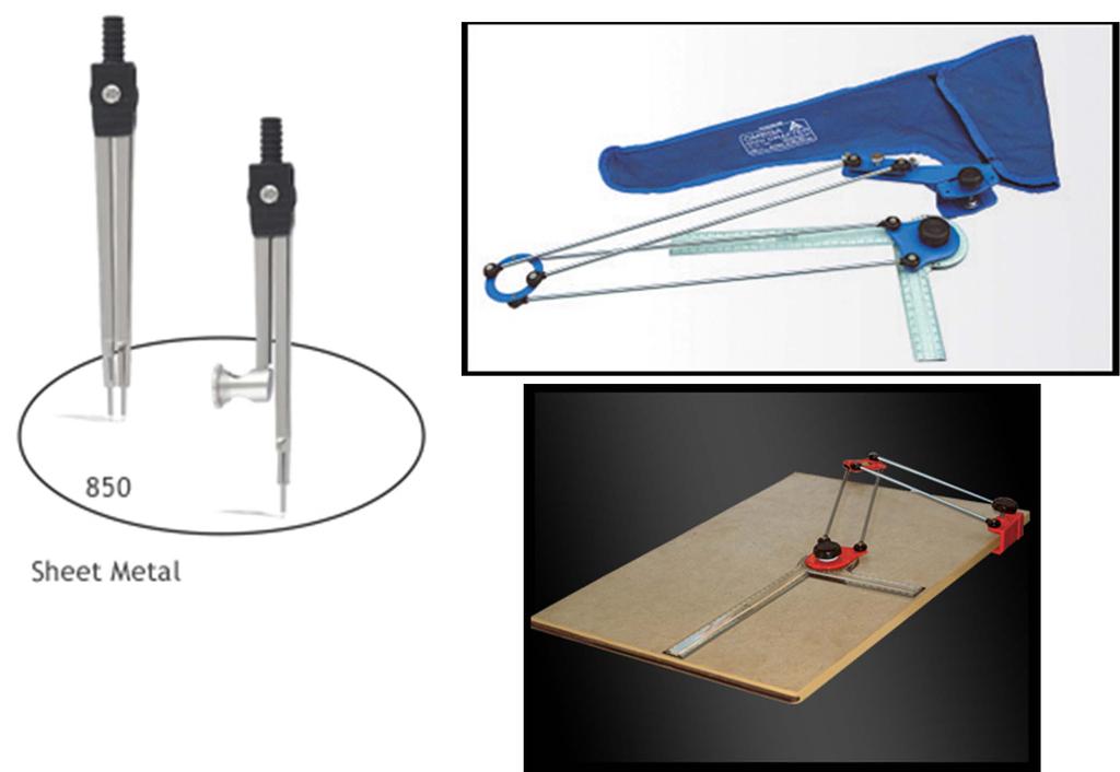
6 Compass: Bow compass is used for drawing small circles up to 30 mm diameter. In this, the inclined cut of the lead is turned inside as shown in the figure. Note: Pro-circle can also be used for drawing small circles up to 30 mm diameter. Large compass is used to draw circles from 30 mm to 120 mm diameter. In this the inclined cut of the lead is turned outside as shown in the figure. Up to 120 mm diameter, circles can be drawn with the legs of the compass kept straight. 6
7 For drawing larger circles both the legs must be bent at their knee joints, so that they are perpendicular to the surface of the paper. For drawing circles of 120 to 300 mm diameter both the needle point leg and the pencil leg should be bent at the knuckle joints so as to be perpendicular to the surface of the paper. For drawing larger circles of more than 300 mm diameter, lengthening bar attachment is used. For this, the lower part of the pencil leg is detached and lengthening bar is inserted in its place. The detached part is then fitted at the end of the lengthening bar. 7

8 In any compass the pencil / lead should project 1 mm less than the needle point as shown in the figure. While taking measurements using compass / divider, place the compass / divider such that it is inclined by 45 0 to the surface of the paper. The bottom horizontal edges of drawing board, pading sheet and drawing sheet should coincide as shown in the figure. The right vertical edges of drawing board, pading sheet and drawing sheet should coincide as shown in the figure. Use double sided tape instead of cello tape. 8
9 How to fix the mini drafter on the drawing board? A miniature of drafting machine is mini drafter. The mini drafter should be positioned on the top left hand side of the drawing board such that the scales ( horizontal and vertical ) of the mini drafter covers the drawing space fully. Note : The longer scale of the mini drafter should be horizontal and called as horizontal scale. The shorter scale of the mini drafter should be vertical and called as vertical scale. Loose the adjusting knob and clamping knob. The horizontal scale of the drafter should be aligned with the top horizontal edge of the drawing sheet. Also, make the mark in the drafter to coincide with 0 0 in the protractor. Holding the horizontal scale of the drafter in this position, tight the adjusting knob first and then tight the clamping knob. Now the mini drafter can be used to draw horizontal and vertical lines. After drawing inclined lines, make the horizontal scale (or vertical scale) of the drafter to align with any previous horizontal line ( or vertical line) and tight the adjusting knob. How to take angles using mini drafter? For taking angles from the vertical line, rotate the vertical scale of the mini-drafter clockwise or anti clockwise to the required angle and draw the inclined line using vertical scale. For taking angles from the horizontal line, rotate the horizontal scale of the mini-drafter clockwise or anti clockwise to the required angle and draw the inclined line using horizontal scale. 9
10 Layout of A2 size drawing sheet for assignment work: Title block is necessary and fold the drawing sheet(six fold) as given below. ALL DIMENSIONS ARE IN mm should be written above the title block. If any different scale is used write that beneath the corresponding problem. 10
11 Layout of A3 size drawing sheet for Unit and Model exams: Title block is not necessary. Write your roll no., branch and section with pen at the bottom right end of the drawing sheet. For that take size 7 mm. Fold the drawing sheet in the middle (one fold) such that your roll no. is visible. Write ALL DIMENSIONS ARE IN mm and Scale: 1 : 1 above your roll no. For that take size 5 mm. If any different scale is used write that beneath the corresponding problem. 11
12 Layout of A3 size drawing sheet for university exams: 5 sheets will be given. Title block is not necessary. Write your registration no. etc., only in the paper provided in front and not in the drawing sheets. It is not necessary to fold the drawing sheets. Write ALL DIMENSIONS ARE IN mm and Scale: 1 : 1 at the bottom right end of all the sheets. For that take size 5 mm. If any different scale is used write that beneath the corresponding problem. The left side 20 mm is given for filing and binding purposes. Border line is a very thick line which serves as a frame for the drawing sheet. 12
13 Title block for assignment work: For title of the drawing take size 7 mm. For others take size 5 mm. If more than one drawing sheet is used for a particular TITLE OF THE DRAWING, sheet no. is n/p, where n is the sheet no. and p is the total no. of sheets. i.e. if for projections of lines 2 sheets (not pages) are used, then sheet no. is 1/2 and 2/2. The symbol for first angle projection is drawn. Write your name, roll no., branch and section with pen. 13
14 How to fold the A2 size drawing sheets for assignment work? Mark 190 mm from the right edge of the drawing sheet. Mark 186 mm from the previous mark. Mark 20 mm from the left edge of the drawing sheet. Mark 297 mm from the bottom edge of the drawing sheet on the reverse side. Coincide the first fold with third fold to get second fold. Coincide the third fold with the border line which is 20 mm to the right of left edge of drawing sheet to get fourth fold. Fifth and sixth folds are back folds. All larger size drawing sheets i.e. A0, A1, A2 and A3 are folded to A4 size sheet. 14
15 Drawing pencils are made in many grades. The grade HB denotes medium soft. The grades H, 2H, 3H 9H denotes the degree of hardness (of graphite lead) in an increasing order. So, the darkness of the line made by the pencil goes on decreasing. Similarly, grades B, 2B, 3B 7B denotes the degree of softness (of graphite lead) in an increasing order. So, the darkness of the line made by the pencil goes on increasing. The grade of the pencil / lead is decided by the amount of graphite mixed with clay. That is, more amount of graphite mixed with less amount of clay increases the softness of the pencil / lead and thereby increases the darkness of the line and vice versa. For better understanding of any object, it is essential to differentiate the various types of lines. HB pencil ( Very thick line ) Border, Title block, Arrow head and Free hand sketch. H pencil ( Thick line) 2H pencil ( Thin line ) Final projections, Hidden edges, Lettering (Alphabets & Numbers) Reference lines, Projectors, Construction lines, Dimension lines, Extension lines, Leader lines, Section lines and Centre lines(axis). Use micro tip pencil to get neat drawings. Use micro tip pencil (0.5 mm lead of grade H) to replace H and 2H wooden pencils. While using the above micro tip pencil care should be taken to differentiate thick and thin lines. For very thick line use micro tip pencil (0.5 mm lead of grade HB). Note: Micro tip pencils, otherwise known as clutch pencils or mechanical pencils, with 0.5 mm thick leads of different grades viz. HB, H and 2H are preferred than wooden pencils, as they need no sharpening. 15
16 How to draw axis? Axis should be drawn as a long-dashed dotted thin line as shown below. Axis should extend beyond the boundary of a figure by a short distance. Scale: Drawing size : Actual size 1 : 1 Full size scale 2 : 1, 3 : 1, 100 : 1, Enlargement scale 1 : 2, 1 : 3, 1 : 100, Reduction scale Note : Whatever the scale may be, the angle remains the same. Whatever the scale may be, only the actual size should be mentioned in the drawing while dimensioning. If you use enlargement scale or reduction scale mention that beneath the corresponding problem. Eg. SCALE : 2 : 1 Usage of mini drafter is a must. For drawing arrow heads remember the ratio 3 : 1. It dosen t mean 3 mm : 1 mm. Shade the closed arrow head with HB pencil. Always draw the arrow heads proportionate to the space available between the extension lines. 16

17 Lettering: In an engineering drawing, it is necessary that the drawing of a component should accompany with some written details, to convey the technical information such as name of the company, part details, information regarding the component, manufacturing process, scale etc. Representing the above particulars and sizes of a component on an engineering drawing is known as Lettering. Note: Lettering includes both alphabets and numbers. Lettering should be done with free hand and not with drawing instruments. Both vertical and inclined letters are in use. In an engineering drawing all the letters must be in upper-case and lower-case letters are used for abbreviations. The scale (other than full size scale) and required answers should be written (with H pencil) beneath the corresponding problem taking the size of letters (use vertical capital letters) as 5 mm. Alphabets and numbers should be obtained in single stroke of the pencil. 17
18 The following figures illustrates the Aligned system of dimensioning: 18
19 4 QUADRANT THEORY FOUR QUADRANTS FRP/V.P. TOP DIRECTION III II X Y IV I HRP/ H.P. FRONT DIRECTION 19
20 VP 2 nd Quad. 1 ST Quad. Y Observer X Y HP X 3 rd Quad. 4 th Quad. THIS QUADRANT PATTERN, IF OBSERVED ALONG X-Y LINE ( IN RED ARROW DIRECTION) WILL EXACTLY APPEAR AS SHOWN ON RIGHT SIDE AND HENCE, T IS FURTHER USED TO UNDERSTAND ILLUSTRATION PROPERLLY
21 TOP DIRECTION 1 st ANGLE Projection V.P. 1st QUADRANT X Y H.P. FRONT DIRECTION 21


22 FIRST ANGLE PROJECTION FOR T.V. IN THIS METHOD, THE OBJECT IS ASSUMED TO BE SITUATED IN FIRST QUADRANT MEANS ABOVE HP & INFRONT OF VP. OBJECT IS INBETWEEN OBSERVER & PLANE. VP PP FV LSV X Y TV HP ACTUAL PATTERN OF PLANES & VIEWS IN FIRST ANGLE METHOD OF PROJECTIONS
 PLANES BEING TRANSPERENT AND INBETWEEN OBSERVER & OBJECT.")
23 THIRD ANGLE PROJECTION FOR T.V. IN THIS METHOD, THE OBJECT IS ASSUMED TO BE SITUATED IN THIRD QUADRANT ( BELOW HP & BEHIND OF VP. ) PLANES BEING TRANSPERENT AND INBETWEEN OBSERVER & OBJECT. TV X Y LSV FV ACTUAL PATTERN OF PLANES & VIEWS OF THIRD ANGLE PROJECTIONS
24 THEORY OF PROJECTION Projector with light F I L M Light rays Pitcure screen Picture Plane Picture plane of projection Fig. 1 DISPLAY OF FILM FRONT VIEW H L Source of Light Light rays Object Fig. 2 Source of Light at infinity H L Fig. 3 24
25 Projection: Assume the visual rays from the eye of the observer touch the boundaries of an object and proceed further to penetrate a plane. A line or a smooth curve joining the penetration points is called as the projection of the given object. Normally the object is between the observer and the plane. Plane of projection: The plane used for projecting the given object is called as the plane of projection. Projectors: They are the rays of sight containing the point and meeting the corresponding plane of projection. Orthographic projection: If the projectors drawn from the object are perpendicular (orthogonal) to the projection plane and are parallel to each other, then, such a projection is called orthographic projection. The observer is assumed to be at an infinite distance from the object in order to get parallel and perpendicular projectors. The orthographic projections has the same size as that of the object. 25
26 Difference between first angle projection and third angle projection methods: Sl.No. First angle projection method Third angle projection method The object is placed in the first quadrant The object is placed in the third quadrant 1. and the projections are obtained. and the projections are obtained. The top view is below the front view. The top view is above the front view. 2. Right side view is drawn to the left of Right side view is drawn to the right of the front view and vice versa. the front view and vice versa The object is kept between the observer and the principal plane of projection. Each projection shows the view of that surface which is farthest from the plane concerned. The projection plane lies between the object and the observer. The projection planes are assumed to be transparent. Each projection shows the view of that surface which is nearest to the plane concerned. In third angle projection method for eg., right side view is drawn to the right of front view where as in first angle projection method right side view is drawn to the left of front view which is more easier to interpret the drawing and understand the object. So, first angle projection method is preferred rather than third angle projection method. In second angle projection, both the top and front views appear above the reference line. If the object is kept in the fourth quadrant, both the top and front views appear below the reference line. Thus, showing the projections on a flat surface becomes inconvenient. Hence the second and fourth quadrants are not preferred. 26
27 Methods of Drawing Orthographic Projections First Angle Projections Method Here views are drawn by placing object in 1 st Quadrant ( Fv above X-y, Tv below X-y ) FV TV SYMBOLIC PRESENTATION OF BOTH METHODS WITH AN OBJECT STANDING ON HP ( GROUND) ON IT S BASE. NOTE:- Third Angle Projections Metho Here views are drawn by placing object in 3 rd Quadrant. ( Tv above X-y, Fv below X-y ) X Y X Y HP term is used in 1 st Angle method & For the same Ground term is used in 3 rd Angle method of projections G TV FV L
(As per New Revised Syllabus of Anna University) Department of Mechanical Engineering. SATHYABAMA UNIVERSITY Jeppiaar Nagar, Chennai
 Department of Mechanical Engineering. SATHYABAMA UNIVERSITY Jeppiaar Nagar, Chennai") (1*,1((5,1* *5$3+,&6 (As per New Revised Syllabus of Anna University) Dr. S.RAMACHANDRAN, M.E., Ph.D. Professor & Head K. PANDIAN, M.E., E.V.V.RAMANAMURTHY, M.Tech., R. DEVARAJ, M.E., Associate Professors
(1*,1((5,1* *5$3+,&6 (As per New Revised Syllabus of Anna University) Dr. S.RAMACHANDRAN, M.E., Ph.D. Professor & Head K. PANDIAN, M.E., E.V.V.RAMANAMURTHY, M.Tech., R. DEVARAJ, M.E., Associate Professors
Lecture 6 ( ): Theory of Multi-view Orthographic Projections
: Theory of Multi-view Orthographic Projections") Lecture 6 (06.08.12): Theory of Multi-view Orthographic Projections Dr. Sharad Gokhale Civil Engineering Department, IIT Guwahati 208, M-Block, Academic Complex Email: sharadbg@iitg.ernet.in Telephone
Lecture 6 (06.08.12): Theory of Multi-view Orthographic Projections Dr. Sharad Gokhale Civil Engineering Department, IIT Guwahati 208, M-Block, Academic Complex Email: sharadbg@iitg.ernet.in Telephone
DRAWING INSTRUMENTS AND THEIR USES
 Chapter - 1A DRAWING INSTRUMENTS AND THEIR USES Drawing Instruments are used to prepare neat and accurate Drawings. To a greater extent, the accuracy of the Drawings depend on the quality of instruments
ORTHOGRAPHIC PROJECTION
 ORTHOGRAPHIC PROJECTION INTRODUCTION Any object has three dimensions, that is, length, width and thickness. A projection is defined as a representation of an object on a two dimensional plane. The projections
Chapter 1 Overview of an Engineering Drawing
 Chapter 1 Overview of an Engineering Drawing TOPICS Graphics language Engineering drawing Projection methods Orthographic projection Drawing standards TOPICS Traditional Drawing Tools Lettering Freehand
DELHI TECHNOLOGICAL UNIVERSITY ENGINEERING GRAPHICS LAB MANUAL
 DELHI TECHNOLOGICAL UNIVERSITY ENGINEERING GRAPHICS LAB MANUAL NAME: - ROLL NO: - GROUP: - BRANCH: - GROUP TEACHER: Page 1 www.rooplalrana.com 1 GENERAL INSTRUCTIONS FOR ENGG. GRAPHICS LAB 1) Students
Drawing sheet: - The various size of the drawing sheet used for engineering drawing as per IS Are listed in the table
 Dronacharya Group of Institutions, Greater Noida Computer Aided Engineering Graphics (CAEG) (NCE 151/251) List of Drawing Sheets: 1. Letter writing & Dimensioning. 2. Projection of Points & Lines. 3. Projection
UNIT 5a STANDARD ORTHOGRAPHIC VIEW DRAWINGS
 UNIT 5a STANDARD ORTHOGRAPHIC VIEW DRAWINGS 5.1 Introduction Orthographic views are 2D images of a 3D object obtained by viewing it from different orthogonal directions. Six principal views are possible
AutoCAD 2D-I. Module 1: Introduction to Drawing Tools. IAT Curriculum Unit PREPARED BY. January 2011
 AutoCAD 2D-I Module 1: Introduction to Drawing Tools PREPARED BY IAT Curriculum Unit January 2011 Institute of Applied Technology, 2011 Module 1: Introduction to Drawing Tools Module Objectives After
GE ENGINEERING GRAPHICS
 ANNA UNIVERSITY, CHENNAI (REGULATION GE8152 - ENGINEERING GRAPHICS B.E SEMESTER I Lecture Tutorial Practical Marks Credits Total Hours 2 0 3 100 4 90 Mr.S.Gokul (Asst. Prof/Mech) Sri Eshwar College of
MISS. HANNA S CLASSROOM RULES
 MISS. HANNA S CLASSROOM RULES 1. My students never fail. I believe in you and so shall you! Miss. Hanna s Quote! 2. Come to class on time. 3. Bring a positive attitude. 4. Come prepared and bring your
ME 111: Engineering Drawing
 ME 111: Engineering Drawing Lecture 5 12-08-2011 Orthographic projection and Projection of Points Indian Institute of Technology Guwahati Guwahati 781039 1 Orthographic Projection A parallel projection
Orthographic Projection
 Orthographic Projection Why Orthographic Projection is used in technical drawing Orthographic projection is a method of producing a number of separate two-dimensional inter-related views, which are mutually
Introduction CHAPTER Graphics: A Tool to Communicate Ideas
 CHAPTER 1 Introduction 1.1 Graphics: A Tool to Communicate Ideas Engineering graphics or drawing is the universal language of engineers. An engineer communicate his idea to others with the help of this
Unit-5 ISOMETRIC PROJECTION
 Unit-5 ISOMETRIC PROJECTION Importance Points in Isometric: 1. For drawing the isometric, the object must be viewed such that either the front -right or the left edges becomes nearest. 2. All vertical
Chapter 4 ORTHOGRAPHIC PROJECTION
 Chapter 4 ORTHOGRAPHIC PROJECTION 4.1 INTRODUCTION We, the human beings are gifted with power to think. The thoughts are to be shared. You will appreciate that different ways and means are available to
Engineering Graphics. Class 2 Drafting Instruments Mohammad Kilani
 Engineering Graphics Class 2 Drafting Instruments Mohammad Kilani Drafting Instruments A Design is as good as its instruments A engineering drawing is a highly stylized graphic representation of an idea.
ORTHOGRAPHIC PROJECTIONS. Ms. Sicola
 ORTHOGRAPHIC PROJECTIONS Ms. Sicola Objectives List the six principal views of projection Sketch the top, front and right-side views of an object with normal, inclined, and oblique surfaces Objectives
ORTHOGRAPHIC PROJECTION
 ORTHOGRAPHIC PROJECTION C H A P T E R S I X OBJECTIVES 1. Recognize and the symbol for third-angle projection. 2. List the six principal views of projection. 3. Understand which views show depth in a drawing
ENGINEERING DRAWING. 1. Set squares are used to draw different angles. What is the angel a formed by the 45⁰ set square? Give a brief answer.
 ENGINEERING DRAWING 1. Set squares are used to draw different angles. What is the angel a formed by the 45⁰ set square? Give a brief answer. 2. Which is the correct method of hatching a plane surface?
Fundamentals for building Drawing
 Fundamentals for building Drawing What is Drawing Introduction Knowledge of preparing and understanding drawing will prove to be an invaluable aid while performing their jobs effectively, efficiently.
TIME SCHEDULE. Module Topic Periods 1 Importance of Engineering Graphics Drawing Instruments Drawing Standards Lettering and Numbering
 COURSE TITLE : ENGINEERING GRAPHICS (First Semester) COURSE CODE : COURSE CATEGORY : F PERIODS/WEEK : 3 PERIODS/SEMESTER : 54 CREDITS : Examination in the Second Semester RATIONALE: Engineering Graphics
Study Unit. Auxiliary Views. This sneak preview of your study material has been prepared in advance of the book's actual online release.
 Study Unit Auxiliary Views This sneak preview of your study material has been prepared in advance of the book's actual online release. iii Preview You re entering now into another subject area in your
Chapter 1 Introduction
 Chapter 1 Introduction Contents Engineering drawing Drawing standards Drawing sheet Scale Lettering Line types Engineering Drawing Contents Engineering Drawing Effectiveness of Graphic Language 1. Try
ENGINEERING GRAPHICS ESSENTIALS
 ENGINEERING GRAPHICS ESSENTIALS with AutoCAD 2012 Instruction Introduction to AutoCAD Engineering Graphics Principles Hand Sketching Text and Independent Learning CD Independent Learning CD: A Comprehensive
ME 111: Engineering Drawing
 ME 111: Engineering Drawing Lecture # 01 Introduction For more detail, visit http://shilloi.iitg.ernet.in/~psr/ Indian Institute of Technology Guwahati Guwahati 781039 1 Syllabus 1. Importance of engineering
Multi-View Drawing Review
 Multi-View Drawing Review Sacramento City College EDT 300/ENGR 306 EDT 300 / ENGR 306 - Chapter 5 1 Objectives Identify and select the various views of an object. Determine the number of views needed to
2. Line composed of closely and evenly spaced short dashes in a drawing represents
 1. Hidden lines are drawn as (a) dashed narrow lines (b) dashed wide lines (c) long-dashed dotted wide line (d) long-dashed double dotted wide line Ans: (a) 2. Line composed of closely and evenly spaced
Multiviews and Auxiliary Views
 Multiviews and Auxiliary Views Multiviews and Auxiliary Views Objectives Explain orthographic and multiview projection. Identifying the six principal views. Apply standard line practices to multiviews
CHAPTER 01 PRESENTATION OF TECHNICAL DRAWING. Prepared by: Sio Sreymean
 CHAPTER 01 PRESENTATION OF TECHNICAL DRAWING Prepared by: Sio Sreymean 2015-2016 Why do we need to study this subject? Effectiveness of Graphics Language 1. Try to write a description of this object. 2.
ENGINEERING DRAWING INTRODUCTION
 ENGINEERING DRAWING INTRODUCTION Drawing is the graphical language of engineers which is built upon certain basic principles and standards. A good drawing can be prepared making use of these principles
Beginning Engineering Graphics 3 rd Week Lecture Notes Instructor: Edward N. Locke Topic: The Coordinate System, Types of Drawings and Orthographic
 Beginning Engineering Graphics 3 rd Week Lecture Notes Instructor: Edward N. Locke Topic: The Coordinate System, Types of Drawings and Orthographic 1 st Subject: The Cartesian Coordinate System The Cartesian
Understanding Projection Systems
 Understanding Projection Systems A Point: A point has no dimensions, a theoretical location that has neither length, width nor height. A point shows an exact location in space. It is important to understand
Orthographic Drawing (Architectural Board Drafting)
") Design and Drafting Description In this activity, the teacher will introduce orthographic projection, in which a multi-view drawing shows how the sides of an object are related to each another. Students
Design and Drafting Description In this activity, the teacher will introduce orthographic projection, in which a multi-view drawing shows how the sides of an object are related to each another. Students
Chapter 1 Overview of a Technical Drawing
 Chapter 1 Overview of a Technical Drawing TOPICS Graphics language Engineering drawing Projection methods Orthographic projection Drawing standards TOPICS Traditional Drawing Tools Lettering Dimensioning
Engineering Graphics Essentials with AutoCAD 2015 Instruction
 Kirstie Plantenberg Engineering Graphics Essentials with AutoCAD 2015 Instruction Text and Video Instruction Multimedia Disc SDC P U B L I C AT I O N S Better Textbooks. Lower Prices. www.sdcpublications.com
Multiview Drawing. Definition: Graphical representation of a 3- dimensional object on one plane (sheet of paper) using two or more views.
 using two or more views.") Multiview Drawing Definition: Graphical representation of a 3- dimensional object on one plane (sheet of paper) using two or more views. Multiview Drawing Another name for multiview drawing is orthographic
Multiview Drawing Definition: Graphical representation of a 3- dimensional object on one plane (sheet of paper) using two or more views. Multiview Drawing Another name for multiview drawing is orthographic
At the conclusion of this unit you should be able to accomplish the following with a 70% accuracy
 7 Multiview Drawing OBJECTIVES At the conclusion of this unit you should be able to accomplish the following with a 70% accuracy 1. explain the importance of mulitview drawing as a communication tool far
ISOMETRIC PROJECTION. Contents. Isometric Scale. Construction of Isometric Scale. Methods to draw isometric projections/isometric views
 ISOMETRIC PROJECTION Contents Introduction Principle of Isometric Projection Isometric Scale Construction of Isometric Scale Isometric View (Isometric Drawings) Methods to draw isometric projections/isometric
Interpretation of Drawings. An Introduction to the Basic Concepts of Creating Technical Drawings
 Interpretation of Drawings An Introduction to the Basic Concepts of Creating Technical Drawings Introduction In the design process drawings are the main way in which information about an object or product
CE 100 Civil Engineering Drawing Sessional (Lab Manual)
") CE 100 Civil Engineering Drawing Sessional (Lab Manual) Department of Civil Engineering Ahsanullah University of Science and Technology November, 2017 1 Preface This course is designed to provide civil
CE 100 Civil Engineering Drawing Sessional (Lab Manual) Department of Civil Engineering Ahsanullah University of Science and Technology November, 2017 1 Preface This course is designed to provide civil
ENGR 1182 Midterm Exam 1: Study Guide and Practice Problems
 ENGR 1182 Midterm Exam 1: Study Guide and Practice Problems Disclaimer Problems seen in this study guide may resemble problems relating mainly to the pertinent homework assignments. Reading this study
I B.TECH- I SEMESTER DEPARTMENT OF MECHANICAL ENGINEERING ENGINEERING DRAWING
 I B.TECH- I SEMESTER DEPARTMENT OF MECHANICAL ENGINEERING ENGINEERING DRAWING ENGINEERING DRAWING UNIT-V DEFINITIONS: Axonometric Trimetric Dimetric Isometric It is a parallel technique used to create
ENGR 1182 Exam 1 First Mid Term Exam Study Guide and Practice Problems
 Spring Semester 2016 ENGR 1182 Exam 1 First Mid Term Exam Study Guide and Practice Problems Disclaimer Problems in this study guide resemble problems relating mainly to the pertinent homework assignments.
ENGINEERING GRAPHICS 1.0 Introduction Engineering Graphics Drawing as an art Artist Graphic design Engineering graphics engineering drawing
 ENGINEERING GRAPHICS 1.0 Introduction Engineering is the profession in which the knowledge of mathematics and science gained by study, experience and practice is applied with good judgment to develop a
Graphical Communication for Engineering ENSC 204 Final Exam
 Name: Student #: Graphical Communication for Engineering ENSC 204 Final Exam December 16, 2015 Time: 3 hours CLOSED BOOK EXAM Read all the instructions below. Do NOT start the exam until you are told to.
Unit 2.Drawing applied to technology
 Unit 2.Drawing applied to technology Unit 2.Drawing applied to technology What are we going to see in this unit? 2.1 Drawing tools and how to use them 2.2 Drafts and sketches 2.3 Scale 2.4 Diedric system:
Two-Dimensional Drawing
 22 Chapter Cxxxx 40757 3/19/08 10:24 AM Page 1 7% 3% 3% 18% 20% 22 Chapter CXXXX 40757 Page 1 03/18/08 MD 22 Two-Dimensional Drawing objectives After completing this chapter, you should be able to Identify
ENGINEERING GRAPHICS ESSENTIALS
 ENGINEERING GRAPHICS ESSENTIALS Text and Digital Learning KIRSTIE PLANTENBERG FIFTH EDITION SDC P U B L I C AT I O N S Better Textbooks. Lower Prices. www.sdcpublications.com ACCESS CODE UNIQUE CODE INSIDE
UNIT Lines and Symbols
 3 UNIT Lines and Symbols Various lines on a drawing have different meanings. They may appear solid, broken, thick, or thin. Each is designed to help the blueprint reader make an interpretation. The standards
Sketching Fundamentals
 Sketching Fundamentals Learning Outcome When you complete this module you will be able to: Make basic engineering sketches of plant equipment. Learning Objectives Here is what you will be able to do when
Exploring 3D in Flash
 1 Exploring 3D in Flash We live in a three-dimensional world. Objects and spaces have width, height, and depth. Various specialized immersive technologies such as special helmets, gloves, and 3D monitors
TPCT s College of Engineering, Osmanabad. Laboratory Manual. Engineering Graphics. For. First Year Students. Manual Prepared by B. G.
 TPCT s College of Engineering, Osmanabad Laboratory Manual Engineering Graphics For First Year Students Manual Prepared by B. G. Kadam Author COE, Osmanabad TPCT s College of Engineering Solapur Road,
(Ans:d) a. A0 b. A1 c. A2 d. A3. (Ans:b) (Ans:a) (Ans:d) (Ans:d)
 a. A0 b. A1 c. A2 d. A3. (Ans:b) (Ans:a) (Ans:d) (Ans:d)") Multiple Choice Questions (MCQ) on Engineering Drawing (Instruments) The mini drafter serves the purpose of everything except a. Scales b. Set square c. Protractor d. Compass (Ans:d) During operation,
Multiple Choice Questions (MCQ) on Engineering Drawing (Instruments) The mini drafter serves the purpose of everything except a. Scales b. Set square c. Protractor d. Compass (Ans:d) During operation,
Isometric Drawing Chapter 26
 Isometric Drawing Chapter 26 Sacramento City College EDT 310 EDT 310 - Chapter 26 - Isometric Drawing 1 Drawing Types Pictorial Drawing types: Perspective Orthographic Isometric Oblique Pictorial - like
Multiview Projection
 DFTG-1305 Technical Drafting Prof. Francis Ha Session 4 Multiview Projection (or Orthographic Projection) Reading: Geisecke s textbook: 14 th Ed. Chapter 5 p.162 15 th Ed. Chapter 6 p.232 Update: 17-0510
ENGINEERING DRAWING LECTURE 4
 ENGINEERING DRAWING LECTURE 4 Conventions Convention or Code: The representation of any matter by some sign or mark on the drawing is known as convention or code. The convention make the drawing simple
Scale and Dimensioning (Architectural Board Drafting)
") Youth Explore Trades Skills Description In this activity, the teacher will first select an object that is larger than the page and scale it to fit in the designated drawing area to explain architectural
Youth Explore Trades Skills Description In this activity, the teacher will first select an object that is larger than the page and scale it to fit in the designated drawing area to explain architectural
Solutions to Exercise problems
 Brief Overview on Projections of Planes: Solutions to Exercise problems By now, all of us must be aware that a plane is any D figure having an enclosed surface area. In our subject point of view, any closed
Technological Design Mr. Wadowski. Orthographic & Isometric Drawing Lesson
 Technological Design Mr. Wadowski Orthographic & Isometric Drawing Lesson TOPICS Working Drawings, Isometric Drawings & Orthographic Drawings Glass box concept Multiview projection Orthographic projection
Chapter 5 SECTIONS OF SOLIDS 5.1 INTRODUCTION
 Chapter 5 SECTIONS OF SOLIDS 5.1 INTRODUCTION We have studied about the orthographic projections in which a 3 dimensional object is detailed in 2-dimension. These objects are simple. In engineering most
4. Draw the development of the lateral surface of the part P of the cylinder whose front view is shown in figure 4. All dimensions are in cm.
 Code No: Z0122 / R07 Set No. 1 I B.Tech - Regular Examinations, June 2009 ENGINEERING GRAPHICS ( Common to Civil Engineering, Mechanical Engineering, Chemical Engineering, Bio-Medical Engineering, Mechatronics,
DFTG-1305 Technical Drafting Prof. Francis Ha
 DFTG-1305 Technical Drafting Prof. Francis Ha Session 4 Orthographic Projection (or Multiview Projection) Reading: Geisecke s textbook: 14 th Ed. Chapter 5 p.162 15 th Ed. Chapter 6 p.232 Update: 18-0205
technical drawing
 technical drawing school of art, design and architecture nust spring 2011 http://www.youtube.com/watch?v=q6mk9hpxwvo http://www.youtube.com/watch?v=bnu2gb7w4qs Objective abstraction - axonometric view
CLASS views from detail on a grid paper. (use appropriate line types to show features) - Optional views. Turn in for grading on class 6 (06/04)
 - Optional views. Turn in for grading on class 6 (06/04)") CLASS 4 Review: - Projections - Orthographic projections Lab: - 3 views from detail on a grid paper. (use appropriate line types to show features) - Optional views. Turn in for grading on class 6 (06/04)
CLASS 4 Review: - Projections - Orthographic projections Lab: - 3 views from detail on a grid paper. (use appropriate line types to show features) - Optional views. Turn in for grading on class 6 (06/04)
Civil Engineering Drawing
 Civil Engineering Drawing Third Angle Projection In third angle projection, front view is always drawn at the bottom, top view just above the front view, and end view, is drawn on that side of the front
 RAKESH JALLA B.Tech. (ME), M. Tech. (CAD/CAM) Assistant Professor, Department Of Mechanical Engineering, CMR Institute of Technology. Introduction to Engineering Drawing Principles of Engineering Drawing/Graphics:
Engineering Graphics, Class 8 Orthographic Projection. Mohammad I. Kilani. Mechanical Engineering Department University of Jordan
 Engineering Graphics, Class 8 Orthographic Projection Mohammad I. Kilani Mechanical Engineering Department University of Jordan Multi view drawings Multi view drawings provide accurate shape descriptions
Isometric Drawing (Architectural Board drafting)
") Design and Drafting Description Isometric drawings use perspective to communicate a large amount of information in a single drawing. Isometric drawings show three sides of an object, making it easier to
Design and Drafting Description Isometric drawings use perspective to communicate a large amount of information in a single drawing. Isometric drawings show three sides of an object, making it easier to
Change of position method:-
 Projections of Planes PROJECTIONS OF PLANES A plane is a two dimensional object having length and breadth only. Thickness is negligible. Types of planes 1. Perpendicular plane which have their surface
ENGINEERING DRAWING I
 INSTITUTE OF ENGINEERING DEPARTMENT OF MECHANICAL ENGINEERING ENGINEERING DRAWING I [TUTORIAL SHEETS] 1 CONTENTS Sheet No. 1: Technical Lettering 3 Sheet No. 2: Plane Geometrical Construction 5 Sheet No.
B.E. 1 st year ENGINEERING GRAPHICS
 B.E. 1 st year ENGINEERING GRAPHICS Introduction 1. What is an Engineering Graphics and its requirements? A standardized graphic representation of physical objects and their relationship is called Engineering
Graphic representation in technological projects
 1st ESO: Technology, Programming and Robotics Graphic representation in technological projects Author: Guillermo Gómez Revision: Pablo Rivas Martín Contents 1 Prior knowledge... 2 2 Keywords... 2 3 Mindmap
GOVERNMENT POLYTECHNIC, VALSAD MECHANICAL ENGINEERING DEPARTMENT ASSIGNMENT SUB: MECHANICAL DRAFTING (C321901) TERM:172
 TERM:172") GOVERNMENT POLYTECHNIC, VALSAD MECHANICAL ENGINEERING DEPARTMENT ASSIGNMENT SUB: MECHANICAL DRAFTING (C321901) TERM:172 1) When all the dimension are placed above the dimension line, it is called (a) Aligned
GOVERNMENT POLYTECHNIC, VALSAD MECHANICAL ENGINEERING DEPARTMENT ASSIGNMENT SUB: MECHANICAL DRAFTING (C321901) TERM:172 1) When all the dimension are placed above the dimension line, it is called (a) Aligned
Downloaded from ENGINEERING DRAWING. Time allowed : 3 hours Maximum Marks : 70
 ENGINEERING DRAWING Time allowed : 3 hours Maximum Marks : 70 Note : (i) (ii) Attempt all the questions. Use both sides of the drawing sheet, if necessary. (iii) All dimensions are in millimeters. (iv)
AABTKJX by Prentice Hall, Inc. A Pearson Company
 Figure Number: 03-01 Page Number: Principal Items of Equipment. AABTKJX0 Figure Number: 03-02 Page Number: The T-square. AABTKJY0 Figure Number: 03-03 Page Number: Testing the Working Edge of the Drawing
ENGINEERING GRAPHICS 1E9
 Lecture 3 Monday, 15 December 2014 1 ENGINEERING GRAPHICS 1E9 Lecture 3: Isometric Projections Lecture 3 Monday, 15 December 2014 2 What is ISOMETRIC? It is a method of producing pictorial view of an object
Optical Illusion Sketchbook Project Art 1201
 Optical Illusion Sketchbook Project Art 1201 Before beginning our final optical illusion project, we need to practice drawing optical illusions so we will have a better understanding of how to construct
2003 Academic Challenge
 Worldwide Youth in Science and Engineering 2003 Academic Challenge ENGINEERING GRAPHICS TEST - REGIONAL Engineering Graphics Test Production Team Ryan Brown, Illinois State University Author/Team Coordinator
Drafting Dictionary (Mechanical Board Drafting)
") Description In this lesson the teacher will introduce the tools and equipment specific to board drafting. Board drafting (also known as manual drafting) refers to precision drawing with specialized instruments.
Description In this lesson the teacher will introduce the tools and equipment specific to board drafting. Board drafting (also known as manual drafting) refers to precision drawing with specialized instruments.
Principles and Practice
 Principles and Practice An Integrated Approach to Engineering Graphics and AutoCAD 2011 Randy H. Shih Oregon Institute of Technology SDC PUBLICATIONS www.sdcpublications.com Schroff Development Corporation
LECTURE 1 INRTRODUCTION TO CIVIL ENGINEERING DRAWING. Engr. Ali Raza Khalid Civil Engineering drawing
 LECTURE 1 INRTRODUCTION TO CIVIL ENGINEERING DRAWING Engr. Ali Raza Khalid CIVIL ENGINEERING DRAWING COURSE OUTLINE Credit Hours: 2+2= 4 Introduction: Introduction to the subject and drawing equipment.
Surface Developments. Sacramento City College Engineering Design Technology. Surface Developments 1
 Surface Developments Sacramento City College Engineering Design Technology Surface Developments 1 Surface Developments A surface development is a full-size layout of an object made on a single flat plane.
Copyrighted Material. Copyrighted Material. Copyrighted. Copyrighted. Material
 Engineering Graphics ORTHOGRAPHIC PROJECTION People who work with drawings develop the ability to look at lines on paper or on a computer screen and "see" the shapes of the objects the lines represent.
Technology Education Grades Drafting I
 Technology Education Grades 9-12 Drafting I 46 Grade Level: 9, 10, 11, 12 Technology Education, Grades 9-12 Drafting I Prerequisite: None Drafting I is an elective course which provides students the opportunity
Student Name: Teacher: Date: District: Rowan. Assessment: 9_12 T and I IC61 - Drafting I Test 1. Description: Unit C - Sketching - Test 2.
 Student Name: Teacher: Date: District: Rowan Assessment: 9_12 T and I IC61 - Drafting I Test 1 Description: Unit C - Sketching - Test 2 Form: 501 1. The most often used combination of views includes the:
PROJECTIONS PARALLEL CONICAL PROJECTIONS PROJECTIONS OBLIQUE ORTHOGRAPHIC PROJECTIONS PROJECTIONS
 PROJECTIONS CONICAL PROJECTIONS PARALLEL PROJECTIONS OBLIQUE PROJECTIONS ORTHOGRAPHIC PROJECTIONS ISOMETRIC MULTI-VIEW an object; The Description of Forms Behind every drawing of an object is space relationship
UNIT I PLANE CURVES AND FREE HAND SKETCHING CONIC SECTIONS
 UNIT I PLANE CURVES AND FREE HAND SKETCHING CONIC SECTIONS Definition: The sections obtained by the intersection of a right circular cone by a cutting plane in different positions are called conic sections
60 Most Important Engineering Drawing Questions
 1. If a client of yours is having difficulty visualizing a design, what type of drawing would be the easiest to understand? A. axonometric B. three-view orthographic C. one-view orthographic D. bimetric
ENGINEERING GRAPHICS
 ENGINEERING GRAPHICS Time allowed : 3 hours Maximum Marks : 70 Note : (ii) Attempt all the questions. Use both sides of the drawing sheet, if necessary. (iii) All dimensions are in millimetres. (iv) Missing
Second Semester Session Shri Ramdeobaba College of Engineering & Management, Nagpur. Department of Mechanical Engineering
 Second Semester Session- 2017-18 Shri Ramdeobaba College of Engineering & Management, Nagpur. Department of Mechanical Engineering Engineering Drawing Practical Problem Sheet Sheet No.:- 1. Scales and
Sketching in SciTech. What you need to know for graphic communication
 Sketching in SciTech What you need to know for graphic communication Sketching in your Logbook Use pencil Take up the WHOLE PAGE Label things 1. Proportion Each part of the sketch is the right size,
Sketch-Up Guide for Woodworkers
 W Enjoy this selection from Sketch-Up Guide for Woodworkers In just seconds, you can enjoy this ebook of Sketch-Up Guide for Woodworkers. SketchUp Guide for BUY NOW! Google See how our magazine makes you
SIDDHARTH GROUP OF INSTITUTIONS :: PUTTUR
 SIDDHARTH GROUP OF INSTITUTIONS :: PUTTUR Siddharth Nagar, Narayanavanam Road 517583 QUESTION BANK Subject Code : Engineering Graphics& Design Course & Branch : B.Tech ALL Year & Sem : I B.Tech & I Sem
How to Draw with a Grid
 Level: Beginner Flesch-Kincaid Grade Level: 8.3 Flesch-Kincaid Reading Ease: 67.5-6 Pages and 12 Illustrations How to Draw with a Grid Exploring the grid method to draw accurate outline drawings This resource
DMT113 Engineering Drawing. Chapter 3 Stretch System
 DMT113 Engineering Drawing Chapter 3 Stretch System Contents Theory & Multiview Planes 6 Principle Views Multiview Sketching Technique & Perspective First & Third Angle Multiview Representations Theory
INTRODUCTION TO COMPUTER AIDED DRAWING
 Introduction to Computer Aided Drawing 1 1 INTRODUCTION TO COMPUTER AIDED DRAWING INTRODUCTION One of the best ways to communicate one s ideas is through some form of picture or drawing. This is especially
ENGINEERING GRAPHICS UNIT V ISOMETRIC PROJECTION PERSPECTIVE PROJECTION
 ENGINEERING GRAPHICS UNIT V ISOMETRIC PROJECTION PERSPECTIVE PROJECTION 1.PICTORIAL PROJECTIONS To visualize the shape of the whole object in its 3- D form, all the two or three orthographic views of the
How to Design a Geometric Stained Glass Lamp Shade
 This technique requires no calculation tables, math, or angle computation. Instead you can use paper & pencil with basic tech drawing skills to design any size or shape spherical lamp with any number of