CLASS views from detail on a grid paper. (use appropriate line types to show features) - Optional views. Turn in for grading on class 6 (06/04)
|
|
|
- Philomena Manning
- 5 years ago
- Views:
Transcription
1 CLASS 4 Review: - Projections - Orthographic projections Lab: - 3 views from detail on a grid paper. (use appropriate line types to show features) - Optional views. Turn in for grading on class 6 (06/04) Home work: - Multiview Projection Simple (duplicate). Turn in for grading on class 6 (06/04) - Read chapter ORTHOGRAPHIC PROJECTION from the book
2 OBJECTIVES 1. Recognize and sketch the symbol for third-angle projection. 2. List the six principal views of projection. 3. Sketch the top, front, and right-side views of an object with normal, inclined, and oblique surfaces. 4. Understand which views show depth in a drawing showing top, front, and right-side views. 5. Know the meaning of normal, inclined, and oblique surfaces. 6. Transfer depth between the top and right-side views. 7. Label points where surfaces intersect. 2
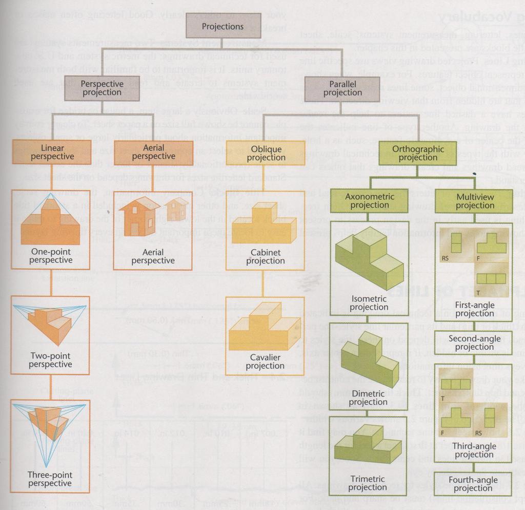
3 PROJECTIONS!!!
4 Perspective Projection Parallel projection

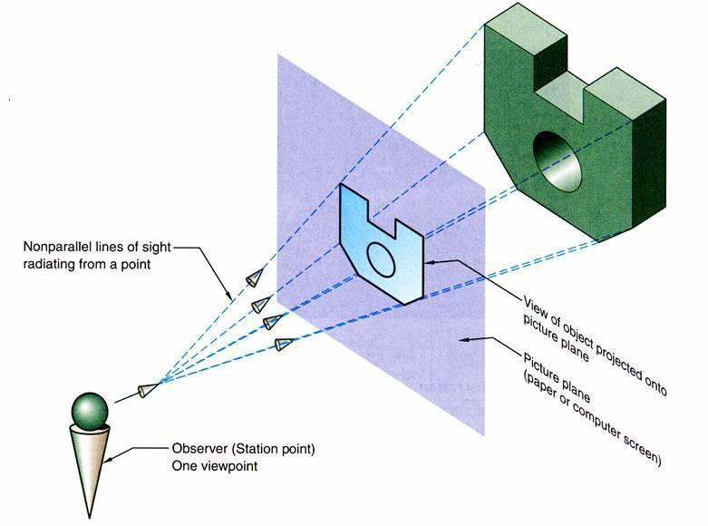
5 Perspective Projection 5
6 Orthographic Projection (Multiview Projection) 6
7 Orthographic Projection The orthographic projections shows the object as it looks from the front, right, left, top, bottom, or back, and are typically positioned relative to each other according to the rules of either first angle or third angle projection. The origin and vector direction of the projectors (also called projection lines) differs, as explained below. 7

8 Different Viewpoint
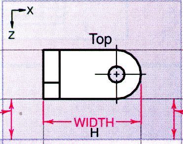
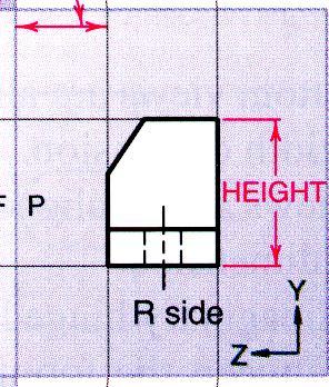
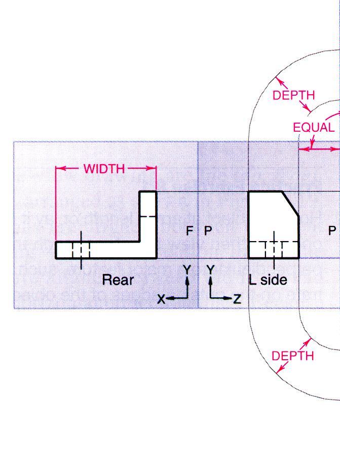
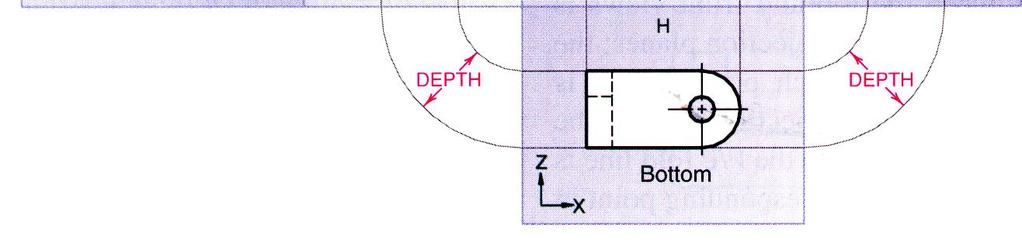
9 Orthographic Projection

10 Standard 2D views!!!

11 The Principal Dimensions of an Object!!!

12 The system of views is called multiview projection. Each view provides certain definite information. For example, a front view shows the true shape and size of surfaces that are parallel to the front of the object. Views of Objects


13 Multiview Projection The system of views is called multiview projection. Each view provides certain definite information.

14 The Six Standard Views Any object can be viewed from six mutually perpendicular directions,


15 Revolving the Object to Produce Views Revolving the Object to Produce Views. You can experience different views by revolving an object.

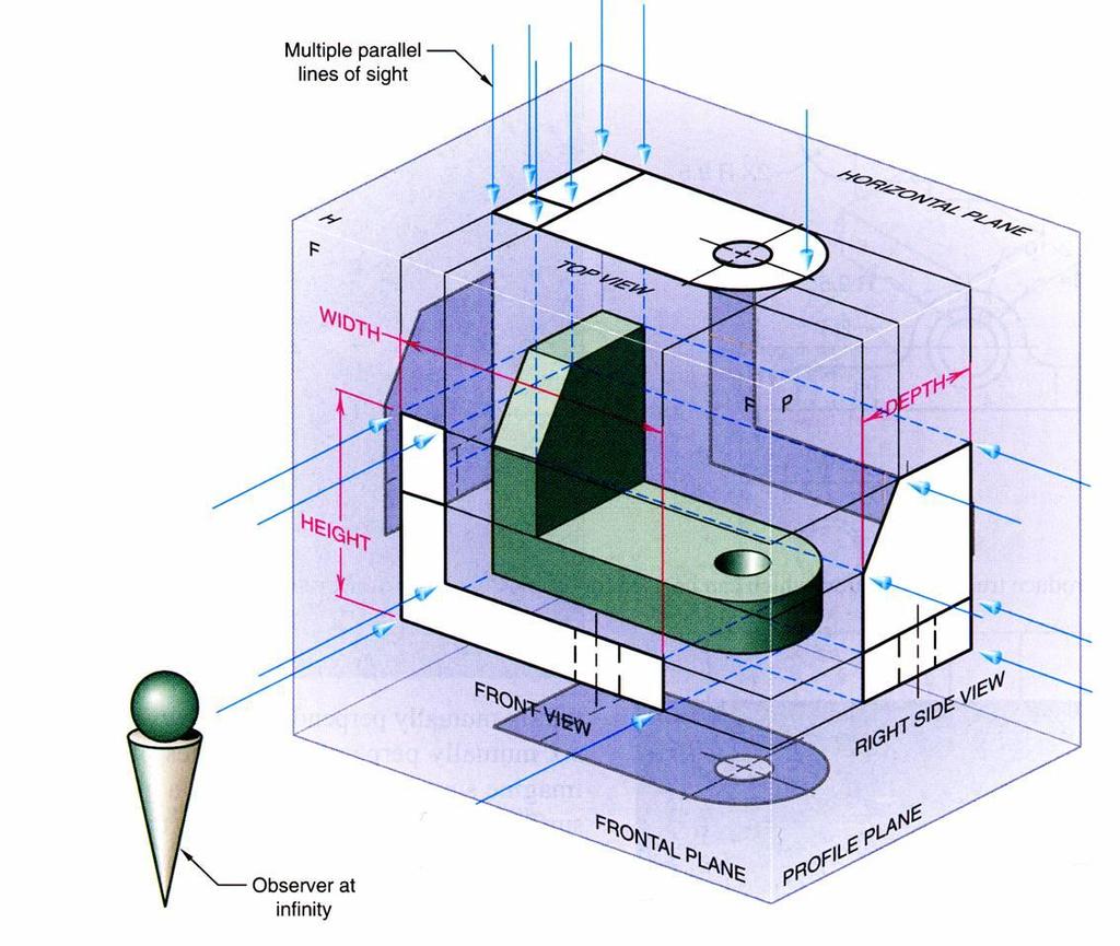
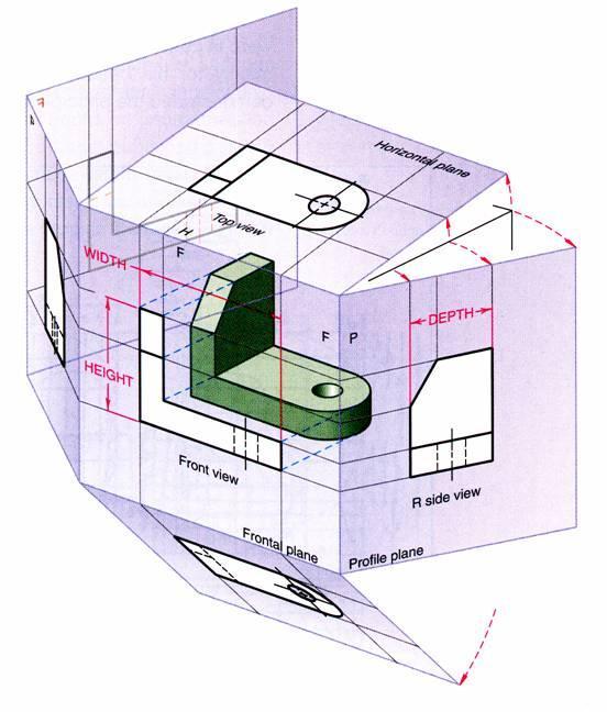
16 Principal Dimensions The three principal dimensions of an object are width, height, and depth. The front view shows only the height and width of the object and not the depth. In fact, any principal view of a 3D object shows only two of the three principal dimensions; the third is found in an adjacent view. Height is shown in the rear, left-side, front, and right-side views. Width is shown in the rear, top, front, and bottom views. Depth is shown in the left-side, top, right-side, and bottom views.
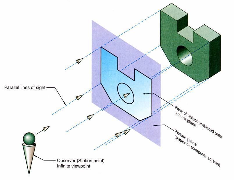
 from all points on the edges or contours of the object extend parallel to each other and perpendicular to the plane of")
17 Projection Method The outline on the plane of projection shows how the object appears to the observer. In orthographic projection, rays (or projectors) from all points on the edges or contours of the object extend parallel to each other and perpendicular to the plane of projection. The word orthographic means at right angles. Projection of an Object

18 Horizontal and Profile Projection Planes Specific names are given to the planes of projection. The front view is projected to the frontal plane. The top view is projected to the horizontal plane. The side view is projected to the profile plane.

19 The Glass Box One way to understand the standard arrangement of views on the sheet of paper is to envision a glass box. If planes of projection were placed parallel to each principal face of the object, they would form a box.
.")
20 Unfolding the Glass Box To organize the views of a 3D object on a flat sheet of paper, imagine the six planes of the glass box being unfolded to lie flat.!!! Note the six standard views (front, rear, top, bottom, right side, left side).

21 The Glass Box Unfolded Lines extend around the glass box from one view to another on the planes of projection. These are the projectors from a point in one view to the same point in another view.
22 Transferring Depth Dimensions The depth dimensions in the top and side views must correspond point-for-point. When using CAD or instruments, transfer these distances accurately. You can transfer dimensions between the top and side views either with dividers or with a scale. You may find it convenient to use a 45 miter line to project dimensions between top and side views.
23 Necessary Views The top, front, and right-side views, arranged together, are called the three regular views because they are the views most frequently used. A sketch or drawing should contain only the views needed to clearly and completely describe the object.
24 Choice of Front View The view chosen for the front view in this case is the side, not the front, of the automobile.!!! The most descriptive view is chosen as the front view
25 Third Angle Projection USA, Canada First Angle Projection Europe, Asia
26 !!! Third Angle Projection USA, Canada First Angle Projection Europe, Asia


27 Hidden Lines Thick, dark lines represent features of the object that are directly visible. Dashed lines represent features that would be hidden behind other surfaces.


28 Centerlines The centerline pattern is used to: show the axis of symmetry for a feature or part indicate a path of motion show the location for bolt circles and other circular patterns The centerline pattern is composed of three dashes: one long dash on each end with a short dash in the middle.
.")
29 PRECEDENCE OF LINES A visible line always takes precedence over and covers up a centerline or a hidden line when they coincide in a view (A and B). A hidden line takes precedence over a centerline (C).
30 Centerlines continued Centerlines (symbol: ) are used to indicate symmetrical axes of objects or features, bolt circles, and paths of motion.

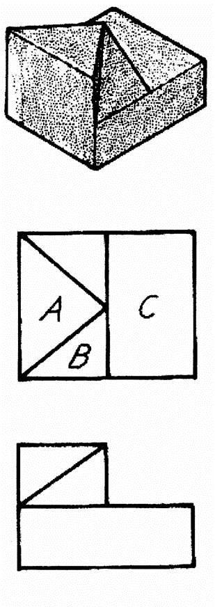
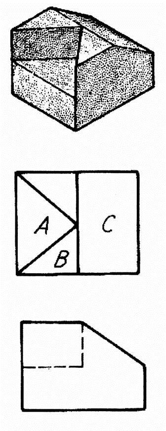
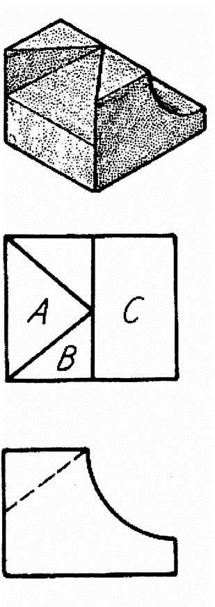
31 Standard Views of Primitive Solids


32 View Orientation Poor orientation Good orientation
33 Use minimum number of views to describe the object Select the most descriptive views
34 Conventional Practices - Intersections

35 Miter Lines Miter lines are used to transfer depth information. 45 o line drawn from point O!!! O Standard multiviews

36 Fillets, Rounds & Chamfers
37 Top view
38

39 Edge Lines Principal & Inclined 2 Principal lines appear vertical, horizontal or as point views. Inclined lines appear inclined in one view.

40 Edge Lines Oblique Oblique line appears inclined in all views 40
41 Principal Planes Principle planes are parallel to principal orthographic planes
42 Inclined Planes Inclined planes are perpendicular to two opposite orthographic planes.
43 Oblique Planes Oblique planes are neither parallel nor perpendicular to any principal orthographic planes.
44 Type of Planes Oblique Principal Inclined


45 VIEWS OF SURFACES There are terms used for describing a surface s orientation to the plane of projection. The three orientations that a plane surface can have to the plane of projection are normal, inclined, and oblique. Note how a plane surface that is perpendicular to a plane of projection appears on edge as a straight line


46 Edge View of a Plane Principal planes appear in true size in one plane and as an edge view in the other two planes.

47 Ken Youssefi Mechanical and Aerospace Engineering Dept., SJSU 47

48 5/8 Ken Youssefi Mechanical and Aerospace Engineering Dept., SJSU 48
49 Instructions: 1. Draw a Front View. Leave space on the bottom for the name of the view. 2. Project construction lines to the Top and Right Side views. 3. Draw Top view. Draw a Miter Line. Using Miter line transfer measurements to the Right side view. 4. Do not use ruler for taking measurements. 5. Place names (1/8 height) of the views on 5/8 distance form the bottom of each view
ORTHOGRAPHIC PROJECTION
 ORTHOGRAPHIC PROJECTION C H A P T E R S I X OBJECTIVES 1. Recognize and the symbol for third-angle projection. 2. List the six principal views of projection. 3. Understand which views show depth in a drawing
ORTHOGRAPHIC PROJECTIONS. Ms. Sicola
 ORTHOGRAPHIC PROJECTIONS Ms. Sicola Objectives List the six principal views of projection Sketch the top, front and right-side views of an object with normal, inclined, and oblique surfaces Objectives
Multiviews and Auxiliary Views
 Multiviews and Auxiliary Views Multiviews and Auxiliary Views Objectives Explain orthographic and multiview projection. Identifying the six principal views. Apply standard line practices to multiviews
Multiview Drawing. Definition: Graphical representation of a 3- dimensional object on one plane (sheet of paper) using two or more views.
 using two or more views.") Multiview Drawing Definition: Graphical representation of a 3- dimensional object on one plane (sheet of paper) using two or more views. Multiview Drawing Another name for multiview drawing is orthographic
Multiview Drawing Definition: Graphical representation of a 3- dimensional object on one plane (sheet of paper) using two or more views. Multiview Drawing Another name for multiview drawing is orthographic
Orthographic Projection
 Orthographic Projection Why Orthographic Projection is used in technical drawing Orthographic projection is a method of producing a number of separate two-dimensional inter-related views, which are mutually
DMT113 Engineering Drawing. Chapter 3 Stretch System
 DMT113 Engineering Drawing Chapter 3 Stretch System Contents Theory & Multiview Planes 6 Principle Views Multiview Sketching Technique & Perspective First & Third Angle Multiview Representations Theory
Multiview Projection
 DFTG-1305 Technical Drafting Prof. Francis Ha Session 4 Multiview Projection (or Orthographic Projection) Reading: Geisecke s textbook: 14 th Ed. Chapter 5 p.162 15 th Ed. Chapter 6 p.232 Update: 17-0510
Engineering Graphics, Class 8 Orthographic Projection. Mohammad I. Kilani. Mechanical Engineering Department University of Jordan
 Engineering Graphics, Class 8 Orthographic Projection Mohammad I. Kilani Mechanical Engineering Department University of Jordan Multi view drawings Multi view drawings provide accurate shape descriptions
ME 111: Engineering Drawing
 ME 111: Engineering Drawing Lecture 5 12-08-2011 Orthographic projection and Projection of Points Indian Institute of Technology Guwahati Guwahati 781039 1 Orthographic Projection A parallel projection
At the conclusion of this unit you should be able to accomplish the following with a 70% accuracy
 7 Multiview Drawing OBJECTIVES At the conclusion of this unit you should be able to accomplish the following with a 70% accuracy 1. explain the importance of mulitview drawing as a communication tool far
UNIT 5a STANDARD ORTHOGRAPHIC VIEW DRAWINGS
 UNIT 5a STANDARD ORTHOGRAPHIC VIEW DRAWINGS 5.1 Introduction Orthographic views are 2D images of a 3D object obtained by viewing it from different orthogonal directions. Six principal views are possible
Technological Design Mr. Wadowski. Orthographic & Isometric Drawing Lesson
 Technological Design Mr. Wadowski Orthographic & Isometric Drawing Lesson TOPICS Working Drawings, Isometric Drawings & Orthographic Drawings Glass box concept Multiview projection Orthographic projection
MULTIPLE CHOICE QUESTIONS - CHAPTER 6
 MULTIPLE CHOICE QUESTIONS - CHAPTER 6 1. The selection of the front view in executing a multiview drawing of an object is dependent upon the following factors: a. size and shape of the object and their
DFTG-1305 Technical Drafting Prof. Francis Ha
 DFTG-1305 Technical Drafting Prof. Francis Ha Session 4 Orthographic Projection (or Multiview Projection) Reading: Geisecke s textbook: 14 th Ed. Chapter 5 p.162 15 th Ed. Chapter 6 p.232 Update: 18-0205
Student Name: Teacher: Date: District: Rowan. Assessment: 9_12 T and I IC61 - Drafting I Test 1. Description: Unit C - Sketching - Test 2.
 Student Name: Teacher: Date: District: Rowan Assessment: 9_12 T and I IC61 - Drafting I Test 1 Description: Unit C - Sketching - Test 2 Form: 501 1. The most often used combination of views includes the:
11/12/2015 CHAPTER 7. Axonometric Drawings (cont.) Axonometric Drawings (cont.) Isometric Projections (cont.) 1) Axonometric Drawings
 Axonometric Drawings (cont.) Isometric Projections (cont.) 1) Axonometric Drawings") CHAPTER 7 1) Axonometric Drawings 1) Introduction Isometric & Oblique Projection Axonometric projection is a parallel projection technique used to create a pictorial drawing of an object by rotating the
CHAPTER 7 1) Axonometric Drawings 1) Introduction Isometric & Oblique Projection Axonometric projection is a parallel projection technique used to create a pictorial drawing of an object by rotating the
Multi-View Drawing Review
 Multi-View Drawing Review Sacramento City College EDT 300/ENGR 306 EDT 300 / ENGR 306 - Chapter 5 1 Objectives Identify and select the various views of an object. Determine the number of views needed to
ENGINEERING GRAPHICS ESSENTIALS
 ENGINEERING GRAPHICS ESSENTIALS Text and Digital Learning KIRSTIE PLANTENBERG FIFTH EDITION SDC P U B L I C AT I O N S Better Textbooks. Lower Prices. www.sdcpublications.com ACCESS CODE UNIQUE CODE INSIDE
Lecture 6 ( ): Theory of Multi-view Orthographic Projections
: Theory of Multi-view Orthographic Projections") Lecture 6 (06.08.12): Theory of Multi-view Orthographic Projections Dr. Sharad Gokhale Civil Engineering Department, IIT Guwahati 208, M-Block, Academic Complex Email: sharadbg@iitg.ernet.in Telephone
Lecture 6 (06.08.12): Theory of Multi-view Orthographic Projections Dr. Sharad Gokhale Civil Engineering Department, IIT Guwahati 208, M-Block, Academic Complex Email: sharadbg@iitg.ernet.in Telephone
Copyrighted Material. Copyrighted Material. Copyrighted. Copyrighted. Material
 Engineering Graphics ORTHOGRAPHIC PROJECTION People who work with drawings develop the ability to look at lines on paper or on a computer screen and "see" the shapes of the objects the lines represent.
ME1105 Engineering Drawing & Design
 City University London Term 1 Assessment 2008/2009 School of Engineering and Mathematical Sciences ME1105 Engineering Drawing & Design Student Name:.., Group: Examination duration: Reading time: This paper
Engineering Graphics Essentials with AutoCAD 2015 Instruction
 Kirstie Plantenberg Engineering Graphics Essentials with AutoCAD 2015 Instruction Text and Video Instruction Multimedia Disc SDC P U B L I C AT I O N S Better Textbooks. Lower Prices. www.sdcpublications.com
Engineering Drawing Lecture 5 PROJECTION THEORY
 University of Palestine College of Engineering & Urban Planning First Level Engineering Drawing Lecture 5 PROJECTION THEORY Lecturer: Eng. Eman Al.Swaity Eng.Heba hamad PART 1 PROJECTION METHOD TOPICS
ORTHOGRAPHIC PROJECTION
 ORTHOGRAPHIC PROJECTION INTRODUCTION Any object has three dimensions, that is, length, width and thickness. A projection is defined as a representation of an object on a two dimensional plane. The projections
ENGINEERING GRAPHICS ESSENTIALS
 ENGINEERING GRAPHICS ESSENTIALS with AutoCAD 2012 Instruction Introduction to AutoCAD Engineering Graphics Principles Hand Sketching Text and Independent Learning CD Independent Learning CD: A Comprehensive
Question. Question. Product Features The Vocabulary of Design Download from web site. CAD/Fab Orthographic Projection 4
 Orthographic Projection Question What is the name of the feature indicated? A. Countersink B. Counterbore C. Spotface D. Hole E. Stepped hole CAD/Fab Assemblies & Mobility 2 Question Product Features The
Civil Engineering Drawing
 Civil Engineering Drawing Third Angle Projection In third angle projection, front view is always drawn at the bottom, top view just above the front view, and end view, is drawn on that side of the front
Lecture #4 MULTIVIEW PROJECTION RES 112E COMPUTER AIDED TECHNICAL DRAWING ITU
 Lecture #4 MULTIVIEW PROJECTION This week You will learn multi-view projection. The steps to follow are: Projections (ISO-E & ISO-A) Multi-view drawings Views (Basic,Auxiliary, Detailed etc.) Sketching
Chapter 8. Technical Drawings
 Chapter 8 Technical Drawing Technical Drawings Multiview drawings Also called three-view drawings Simple objects take three views Front, top, one side Title block Identifies who did the design Gives date,
AUXILIARY VIEWS C H A P T E R N I N E
 AUXILIARY VIEWS C H A P T E R N I N E Giesecke, Hill, Spencer, Dygdon, Novak, Lockhart, Goodman 1 OBJECTIVES 1. Create an auxiliary view from orthographic views. 2. Draw folding lines or reference-plane
Mechanical Drawing. Unit 2 Study Guide for Chapters 6-10
 Mechanical Drawing Unit 2 Study Guide for Chapters 6-10 Chapter 6 Multiview Drawing Section 6.1 Understanding Orthographic Projection A. Technical Drawing: How can a technical drawing give more accurate
PROJECTIONS PARALLEL CONICAL PROJECTIONS PROJECTIONS OBLIQUE ORTHOGRAPHIC PROJECTIONS PROJECTIONS
 PROJECTIONS CONICAL PROJECTIONS PARALLEL PROJECTIONS OBLIQUE PROJECTIONS ORTHOGRAPHIC PROJECTIONS ISOMETRIC MULTI-VIEW an object; The Description of Forms Behind every drawing of an object is space relationship
Glass Box Projection. Gives you 6 sides to view of an object. 10/2/14 2
 2D Drawings Glass Box Projection Gives you 6 sides to view of an object. 10/2/14 2 We can simplify this for some objects to 3 views Glass Box Approach Glass Box Approach Glass Box Approach Glass Box Approach
Auxiliary view KCEC1101
 Auxiliary view KCEC1101 Introduction There are times when one of the six principal views will not completely describe an object. This is especially true when there are inclined or oblique planes or features
ENGR 1182 Exam 1 First Mid Term Exam Study Guide and Practice Problems
 Spring Semester 2016 ENGR 1182 Exam 1 First Mid Term Exam Study Guide and Practice Problems Disclaimer Problems in this study guide resemble problems relating mainly to the pertinent homework assignments.
ENGINEERING DRAWING. 1. Set squares are used to draw different angles. What is the angel a formed by the 45⁰ set square? Give a brief answer.
 ENGINEERING DRAWING 1. Set squares are used to draw different angles. What is the angel a formed by the 45⁰ set square? Give a brief answer. 2. Which is the correct method of hatching a plane surface?
Graphical Communication
 Chapter 9 Graphical Communication mmm Becoming a fully competent engineer is a long yet rewarding process that requires the acquisition of many diverse skills and a wide body of knowledge. Learning most
Orthographic Projection
 ENG3000 Orthographic Projection 1 Session Objectives To understand the basic principles of orthographic projection To be able to construct orthographic views of simple objects To visualize 3 D objects
ME 113 Computer Aided Engineering Drawing
 ME 113 Computer Aided Engineering Drawing Orthographic Projection - Visualizing Solids and Multiview Drawings Asst.Prof.Dr.Turgut AKYÜREK Çankaya University, Ankara Visualizing Solids and Multiview Drawings
CE 100 Civil Engineering Drawing Sessional (Lab Manual)
") CE 100 Civil Engineering Drawing Sessional (Lab Manual) Department of Civil Engineering Ahsanullah University of Science and Technology November, 2017 1 Preface This course is designed to provide civil
CE 100 Civil Engineering Drawing Sessional (Lab Manual) Department of Civil Engineering Ahsanullah University of Science and Technology November, 2017 1 Preface This course is designed to provide civil
Sketching in SciTech. What you need to know for graphic communication
 Sketching in SciTech What you need to know for graphic communication Sketching in your Logbook Use pencil Take up the WHOLE PAGE Label things 1. Proportion Each part of the sketch is the right size,
Principles and Practice
 Principles and Practice An Integrated Approach to Engineering Graphics and AutoCAD 2011 Randy H. Shih Oregon Institute of Technology SDC PUBLICATIONS www.sdcpublications.com Schroff Development Corporation
GL5: Visualisation and reading drawings
 436-105 Engineering Communications GL5:1 GL5: Visualisation and reading drawings Being able to both: represent a 3D object in multiview drawings interpret a multiview drawing to visualise a 3D object is
SDC PUBLICATIONS. Schroff Development Corporation
 SDC PUBLICATIONS Schroff Development Corporation www.schroff.com www.schroff-europe.com SECTIONING In chapter 3 you will learn how to create various types of sectional views. Sectional views allow you
ENGINEERING GRAPHICS 1E9
 Lecture 3 Monday, 15 December 2014 1 ENGINEERING GRAPHICS 1E9 Lecture 3: Isometric Projections Lecture 3 Monday, 15 December 2014 2 What is ISOMETRIC? It is a method of producing pictorial view of an object
Chapter 1 Overview of an Engineering Drawing
 Chapter 1 Overview of an Engineering Drawing TOPICS Graphics language Engineering drawing Projection methods Orthographic projection Drawing standards TOPICS Traditional Drawing Tools Lettering Freehand
Beginning Engineering Graphics 3 rd Week Lecture Notes Instructor: Edward N. Locke Topic: The Coordinate System, Types of Drawings and Orthographic
 Beginning Engineering Graphics 3 rd Week Lecture Notes Instructor: Edward N. Locke Topic: The Coordinate System, Types of Drawings and Orthographic 1 st Subject: The Cartesian Coordinate System The Cartesian
60 Most Important Engineering Drawing Questions
 1. If a client of yours is having difficulty visualizing a design, what type of drawing would be the easiest to understand? A. axonometric B. three-view orthographic C. one-view orthographic D. bimetric
Exploring 3D in Flash
 1 Exploring 3D in Flash We live in a three-dimensional world. Objects and spaces have width, height, and depth. Various specialized immersive technologies such as special helmets, gloves, and 3D monitors
Engineering Graphics, Class 13 Descriptive Geometry. Mohammad I. Kilani. Mechanical Engineering Department University of Jordan
 Engineering Graphics, Class 13 Descriptive Geometry Mohammad I. Kilani Mechanical Engineering Department University of Jordan Projecting a line into other views Given the front and right side projections
(Ans:d) a. A0 b. A1 c. A2 d. A3. (Ans:b) (Ans:a) (Ans:d) (Ans:d)
 a. A0 b. A1 c. A2 d. A3. (Ans:b) (Ans:a) (Ans:d) (Ans:d)") Multiple Choice Questions (MCQ) on Engineering Drawing (Instruments) The mini drafter serves the purpose of everything except a. Scales b. Set square c. Protractor d. Compass (Ans:d) During operation,
Multiple Choice Questions (MCQ) on Engineering Drawing (Instruments) The mini drafter serves the purpose of everything except a. Scales b. Set square c. Protractor d. Compass (Ans:d) During operation,
Describing an Angle Bracket
 Basics of Drafting Describing an Angle Bracket Orthographic Projection Orthographic drawings represent three dimensional objects in three separate views arranged in a standard manner. Orthographic Views
ENGINEERING DRAWING SKKK 1021 ISOMETRIC DRAWING. Agus Arsad, Azizul Azri Bin Mustaffa 10/2/2012 1
 ENGINEERING DRAWING SKKK 1021 ISOMETRIC DRAWING Agus Arsad, Azizul Azri Bin Mustaffa 10/2/2012 1 LEARNING OUTCOMES ISOMETRIC DRAWING It is expected that students will be able to: Understand the significance
MODELING AND DESIGN C H A P T E R F O U R
 MODELING AND DESIGN C H A P T E R F O U R OBJECTIVES 1. Identify and specify basic geometric elements and primitive shapes. 2. Select a 2D profile that best describes the shape of an object. 3. Identify
Chapter 5 Pictorial sketching
 Chapter 5 Pictorial sketching Contents Freehand sketching techniques Pictorial projections - Axonometric - Oblique Isometric projection vs isometric sketch Isometric sketch from an orthographic views Isometric
ISOMETRIC PROJECTION. Contents. Isometric Scale. Construction of Isometric Scale. Methods to draw isometric projections/isometric views
 ISOMETRIC PROJECTION Contents Introduction Principle of Isometric Projection Isometric Scale Construction of Isometric Scale Isometric View (Isometric Drawings) Methods to draw isometric projections/isometric
2009 Academic Challenge
 2009 Academic Challenge ENGINEERING GRAPHICS TEST STATE FINALS This Test Consists of 50 Questions Engineering Graphics Test Production Team Ryan Brown, Illinois State University Author/Team Leader Kevin
CHAPTER 01 PRESENTATION OF TECHNICAL DRAWING. Prepared by: Sio Sreymean
 CHAPTER 01 PRESENTATION OF TECHNICAL DRAWING Prepared by: Sio Sreymean 2015-2016 Why do we need to study this subject? Effectiveness of Graphics Language 1. Try to write a description of this object. 2.
Add labels to the sides...
 Orthographic Drawings Orthographic Projection A projection on a plane, using lines perpendicular to the plane Graphic communications has many forms. Orthographics is one such form. It was developed as
Engineering Working Drawings Basics
 Engineering Working Drawings Basics Engineering graphics is an effective way of communicating technical ideas and it is an essential tool in engineering design where most of the design process is graphically
Interpretation of Drawings. An Introduction to the Basic Concepts of Creating Technical Drawings
 Interpretation of Drawings An Introduction to the Basic Concepts of Creating Technical Drawings Introduction In the design process drawings are the main way in which information about an object or product
Indian Institute of Technology Kanpur National Programme on Technology Enhanced Learning (NPTEL) Course Title Engineering Graphics
 Course Title Engineering Graphics") Indian Institute of Technology Kanpur National Programme on Technology Enhanced Learning (NPTEL) Course Title Engineering Graphics Lecture 15 Oblique Projections-Part-III by Prof. Nihar Ranjan Patre Department
Indian Institute of Technology Kanpur National Programme on Technology Enhanced Learning (NPTEL) Course Title Engineering Graphics Lecture 15 Oblique Projections-Part-III by Prof. Nihar Ranjan Patre Department
ENGR 1182 Midterm Exam 1: Study Guide and Practice Problems
 ENGR 1182 Midterm Exam 1: Study Guide and Practice Problems Disclaimer Problems seen in this study guide may resemble problems relating mainly to the pertinent homework assignments. Reading this study
Chapter 2: Dimensioning Basic Topics Advanced Topics Exercises
 Chapter 2: Dimensioning Basic Topics Advanced Topics Exercises Dimensioning: Basic Topics Summary 2-1) Detailed Drawings 2-2) Learning to Dimension 2-3) Dimension Appearance and Techniques. 2-4) Dimensioning
Unit 4: Geometric Construction (Chapter4: Geometry For Modeling and Design)
") Unit 4: Geometric Construction (Chapter4: Geometry For Modeling and Design) DFTG-1305 Technical Drafting Instructor: Jimmy Nhan OBJECTIVES 1. Identify and specify basic geometric elements and primitive
Unit 4: Geometric Construction (Chapter4: Geometry For Modeling and Design) DFTG-1305 Technical Drafting Instructor: Jimmy Nhan OBJECTIVES 1. Identify and specify basic geometric elements and primitive
2009 Academic Challenge
 2009 Academic Challenge ENGINEERING GRAPHICS TEST SECTIONAL This Test Consists of 50 Questions Engineering Graphics Test Production Team Ryan Brown, Illinois State University Author/Team Leader Kevin Devine,
Isometric Drawing Chapter 26
 Isometric Drawing Chapter 26 Sacramento City College EDT 310 EDT 310 - Chapter 26 - Isometric Drawing 1 Drawing Types Pictorial Drawing types: Perspective Orthographic Isometric Oblique Pictorial - like
Chapter 5 SECTIONS OF SOLIDS 5.1 INTRODUCTION
 Chapter 5 SECTIONS OF SOLIDS 5.1 INTRODUCTION We have studied about the orthographic projections in which a 3 dimensional object is detailed in 2-dimension. These objects are simple. In engineering most
Philadelphia University Faculty of Engineering Mechanical Engineering Department
 Philadelphia University Faculty of Engineering Mechanical Engineering Department Basics of Engineering Drawing Manual Done by:- Eng. Laith R.I. Batarseh Eng. Hanan Khamis 2017 1 Table of contents SUBJECT
DUE DATE: Friday 4/6/2018 at 3:30 PM
 MECH 130 SPRING 2018 CAD LAB 4 FINAL REVISION HARDCOPIES NEEDED DUE DATE: Friday 4/6/2018 at 3:30 PM After the revised hitch, the ball and the pin parts were created from the Handout call LAB4 PART Creation,
2004 Academic Challenge
 2004 Academic Challenge ENGINEERING GRAPHICS TEST - REGIONAL Engineering Graphics Test Production Team Ryan Brown, Illinois State University Author/Team Coordinator Kevin Devine, Illinois State University
technical drawing
 technical drawing school of art, design and architecture nust spring 2011 http://www.youtube.com/watch?v=q6mk9hpxwvo http://www.youtube.com/watch?v=bnu2gb7w4qs Objective abstraction - axonometric view
1. Open the Feature Modeling demo part file on the EEIC website. Ask student about which constraints needed to Fully Define.
 BLUE boxed notes are intended as aids to the lecturer RED boxed notes are comments that the lecturer could make Control + Click HERE to view enlarged IMAGE and Construction Strategy he following set of
Orthographic Projection 1
 Orthographic Projection 1 What Is Orthographic Projection? Basically it is a way a representing a 3D object on a piece of paper. This means we make the object becomes 2D. The difference between Orthographic
2. Line composed of closely and evenly spaced short dashes in a drawing represents
 1. Hidden lines are drawn as (a) dashed narrow lines (b) dashed wide lines (c) long-dashed dotted wide line (d) long-dashed double dotted wide line Ans: (a) 2. Line composed of closely and evenly spaced
Introduction to Circular Pattern Flower Pot
 Prerequisite Knowledge Previous knowledge of the sketching commands Line, Circle, Add Relations, Smart Dimension is required to complete this lesson. Previous examples of Revolved Boss/Base, Cut Extrude,
Unit-5 ISOMETRIC PROJECTION
 Unit-5 ISOMETRIC PROJECTION Importance Points in Isometric: 1. For drawing the isometric, the object must be viewed such that either the front -right or the left edges becomes nearest. 2. All vertical
Transform 3D objects on to a 2D plane using projections
 PROJECTIONS 1 Transform 3D objects on to a 2D plane using projections 2 types of projections Perspective Parallel In parallel projection, coordinate positions are transformed to the view plane along parallel
Dimensioning. Dimensions: Are required on detail drawings. Provide the shape, size and location description: ASME Dimensioning Standards
 Dimensioning Dimensions: Are required on detail drawings. Provide the shape, size and location description: - Size dimensions - Location dimensions - Notes Local notes (specific notes) General notes ASME
Test Answers and Exam Booklet. Geometric Tolerancing
 Test Answers and Exam Booklet Geometric Tolerancing iii Contents ANSWERS TO THE GEOMETRIC TOLERANCING TEST............. 1 Part 1. Questions Part 2. Calculations SAMPLE ANSWERS TO THE GEOMETRIC TOLERANCING
Brief Introduction to Engineering Graphics The use of drawings to convey information. Sketching freehand straight edge
 Brief Introduction to Engineering Graphics The use of drawings to convey information. Sketching freehand straight edge CAD drawings 2D drafting 3D model to 2D drawings 1 Different Graphical Representation
2016 Academic Challenge
 2016 Academic Challenge ENGINEERING GRAPHICS TEST REGIONAL This Test Consists of 40 Questions Engineering Graphics Test Production Team Ryan K. Brown, Illinois State University Author/Team Leader Mark
7/9/2009. Offset Tool. Offset Tool. Offsetting - Erasing the Original Object. Chapter 8 Construction Tools and Multiview Drawings
 Chapter 8 Construction Tools and Multiview Drawings Use the OFFSET tool to draw parallel lines and curves. Mark points on objects at equal lengths using the DIVIDE tool. Set designated increments on an
2010 Academic Challenge
 2010 Academic Challenge ENGINEERING GRAPHICS TEST STATE FINALS This Test Consists of 40 Questions Engineering Graphics Test Production Team Ryan K. Brown, Illinois State University Author/Team Leader Jacob
DWG 002. Blueprint Reading. Geometric Terminology Orthographic Projection. Instructor Guide
 DWG 002 Blueprint Reading Geometric Terminology Orthographic Projection Instructor Guide Introduction Module Purpose The purpose of the Blueprint Reading modules is to introduce students to production
SolidWorks 95 User s Guide
 SolidWorks 95 User s Guide Disclaimer: The following User Guide was extracted from SolidWorks 95 Help files and was not originally distributed in this format. All content 1995, SolidWorks Corporation Contents
Chapter 1 Overview of a Technical Drawing
 Chapter 1 Overview of a Technical Drawing TOPICS Graphics language Engineering drawing Projection methods Orthographic projection Drawing standards TOPICS Traditional Drawing Tools Lettering Dimensioning
Chapter 1 Introduction
 Chapter 1 Introduction Contents Engineering drawing Drawing standards Drawing sheet Scale Lettering Line types Engineering Drawing Contents Engineering Drawing Effectiveness of Graphic Language 1. Try
Contents. Notes on the use of this publication
 Contents Preface xxiii Scope Notes on the use of this publication xxv xxvi 1 Layout of drawings 1 1.1 General 1 1.2 Drawing sheets 1 1.3 Title block 2 1.4 Borders and frames 2 1.5 Drawing formats 2 1.6
Module 2: Radial-Line Sheet-Metal 3D Modeling and 2D Pattern Development: Right Cone (Regular, Frustum, and Truncated)
") Inventor (5) Module 2: 2-1 Module 2: Radial-Line Sheet-Metal 3D Modeling and 2D Pattern Development: Right Cone (Regular, Frustum, and Truncated) In this tutorial, we will learn how to build a 3D model
Inventor (5) Module 2: 2-1 Module 2: Radial-Line Sheet-Metal 3D Modeling and 2D Pattern Development: Right Cone (Regular, Frustum, and Truncated) In this tutorial, we will learn how to build a 3D model
Orthographic Drawing (Architectural Board Drafting)
") Design and Drafting Description In this activity, the teacher will introduce orthographic projection, in which a multi-view drawing shows how the sides of an object are related to each another. Students
Design and Drafting Description In this activity, the teacher will introduce orthographic projection, in which a multi-view drawing shows how the sides of an object are related to each another. Students
2003 Academic Challenge
 Worldwide Youth in Science and Engineering 2003 Academic Challenge ENGINEERING GRAPHICS TEST - REGIONAL Engineering Graphics Test Production Team Ryan Brown, Illinois State University Author/Team Coordinator
ENGINEERING GRAPHICS 1.0 Introduction Engineering Graphics Drawing as an art Artist Graphic design Engineering graphics engineering drawing
 ENGINEERING GRAPHICS 1.0 Introduction Engineering is the profession in which the knowledge of mathematics and science gained by study, experience and practice is applied with good judgment to develop a
Chapter 5 Pictorial Projection
 Chapter 5 Pictorial Projection Objectives After completing this chapter, the students will be able to Create freehand sketches using the correct sketching techniques. Explainthe difference between axonometric
Starting a 3D Modeling Part File
 1 How to Create a 3D Model and Corresponding 2D Drawing with Dimensions, GDT (Geometric Dimensioning and Tolerance) Symbols and Title Block in SolidWorks 2013-2014 By Edward Locke This tutorial will introduce
Descriptive Geometry CH17 : DEVELOPMENTS
 Descriptive Geometry CH17 : DEVELOPMENTS Developments A development is a flat representation or pattern that when folded together creates a 3D object. Developable Surfaces A developable surface may be
JUNIOR CERTIFICATE 2009 MARKING SCHEME TECHNICAL GRAPHICS HIGHER LEVEL
 . JUNIOR CERTIFICATE 2009 MARKING SCHEME TECHNICAL GRAPHICS HIGHER LEVEL Sections A and B Section A any ten questions from this section Q1 12 Four diagrams, 3 marks for each correct label. Q2 12 2 marks
ME Week 2 Project 2 Flange Manifold Part
 1 Project 2 - Flange Manifold Part 1.1 Instructions This project focuses on additional sketching methods and sketching commands. Revolve and Work features are also introduced. The part being modeled is
Isometric Drawings. Figure A 1
 A Isometric Drawings ISOMETRIC BASICS Isometric drawings are a means of drawing an object in picture form for better clarifying the object s appearance. These types of drawings resemble a picture of an