CHAPTER 01 PRESENTATION OF TECHNICAL DRAWING. Prepared by: Sio Sreymean
|
|
|
- Collin Conley
- 6 years ago
- Views:
Transcription


1 CHAPTER 01 PRESENTATION OF TECHNICAL DRAWING Prepared by: Sio Sreymean
2 Why do we need to study this subject?

3 Effectiveness of Graphics Language 1. Try to write a description of this object. 2. Test your written description by having someone attempt to make a sketch from your description. You can easily understand that The word languages are inadequate for describing the size, shape and features completely as well as concisely. 3
4 Composition of Graphic Language Graphic language in engineering application use lines to represent the surfaces, edges and contours of objects. The language is known as drawing or drafting. A drawing can be done using freehand, instruments or computer methods. 4


5 Freehand drawing The lines are sketched without using instruments other than pencils and erasers. Example 5


6 Instrument drawing Instruments are used to draw straight lines, circles, and curves concisely and accurately. Thus, the drawings are usually made to scale. Example 6


7 Computer drawing The drawings are usually made by commercial software such as AutoCAD, solid works etc. Example 7
8 INTRODUCTION An engineering drawing is a type of technical drawing, used to fully and clearly define requirements for engineered items, and is usually created in accordance with standardized conventions for layout, nomenclature, interpretation, appearance size, etc. Its purpose is to accurately and unambiguously capture all the geometric features of a product or a component. The end goal of an engineering drawing is to convey all the required information that will allow a manufacturer to produce that component. 8

9 PURPOSE OF AN ENGINEERING DRAWING 1. An engineering drawing is not an illustration. 2. It is a specification of the size and shape of a part or assembly. 3. The important information on a drawing is the dimension and tolerance of all of its features. 9


10 Elements of Engineering Drawing Engineering drawing are made up of graphics language and word language. Graphics language Describe a shape (mainly). Word language Describe size, location and specification of the object. 10
11 Basic Knowledge for Drafting Graphics language Word language Line types Projection method Geometric construction Lettering 11


12 PROJECTION METHOD
13 PROJECTION METHOD Perspective Parallel Oblique Orthographic Axonometric Multiview 13
14 PROJECTION THEORY The projection theory is used to graphically represent 3-D objects on 2-D media (paper, computer screen). The projection theory is based on two variables: 1) Line of sight 2) Plane of projection (image plane or picture plane) 14
15 Line of sight is an imaginary ray of light between an observer s eye and an object. There are 2 types of LOS : parallel and converge Parallel projection Line of sight Perspective projection Line of sight 15
16 Plane of projection is an imaginary flat plane which the image is created. The image is produced by connecting the points where the LOS pierce the projection plane. Parallel projection Plane of projection Perspective projection Plane of projection 16
 It is difficult to create. 2) It does not reveal exact shape and size.")
17 DISADVANTAGE OF PERSPECTIVE PROJECTION Perspective projection is not used by engineer for manufacturing of parts, because 1) It is difficult to create. 2) It does not reveal exact shape and size. Width is distorted 17


18 ORTHOGRAPHIC PROJECTION
19 Orthographic" comes from the Greek word for "straight writing (or drawing)." This projection shows the object as it looks from the front, right, left, top, bottom, or back, and are typically positioned relative to each other according to the rules of either First Angle or Third Angle projection. ORTHOGRAPHIC PROJECTION 19
20 PICTORIAL 3-dimensional representations One-point one vanishing point lines that are not vertical or horizontal converge to single point in distance Two-point or Three-point two or three vanishing points With two points, vertical or horizontal lines parallel, but not both With three-point, no lines are parallel Isometric Drawing shows corner of object, but parallel lines on object are parallel in drawing Shows three dimensions, but no vanishing point(s) 20
21 One-point Two-Point 21

22 SYMBOLS FOR THIRD ANGLE (RIGHT)OR FIRST ANGLE (LEFT). First angle projection is the ISO standard and is primarily used in Europe. The 3D object is projected into 2D "paper" space as if you were looking at an X-ray of the object: the top view is under the front view, the right view is at the left of the front view. Third angle projection is primarily used in the United States and Canada, where it is the default projection system according to BS 8888:2006, the left view is placed on the left the top view on the top. 22
23 MEANING Orthographic projection is a parallel projection technique in which the parallel lines of sight are perpendicular to the projection plane Object views from top Projection plane 23

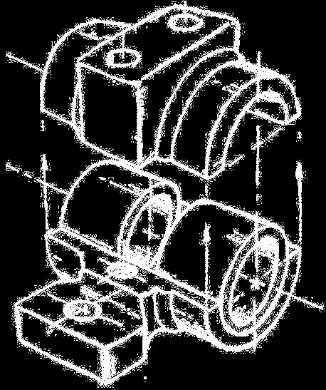
24 IMAGE OF A PART REPRESENTED IN FIRST ANGLE PROJECTION 24
25 Draw object from two / three perpendicular views ORTHOGRAPHIC / MULTIVIEW / Orthographic What it looks like pictorially 25
26 26
27 27


28 ORTHOGRAPHIC VIEW Orthographic view depends on relative position of the object to the line of sight. Two dimensions of an object is shown. More than one view is needed to represent the object. Rotate Tilt Multiview drawing Three dimensions of an object is shown. Axonometric drawing 28
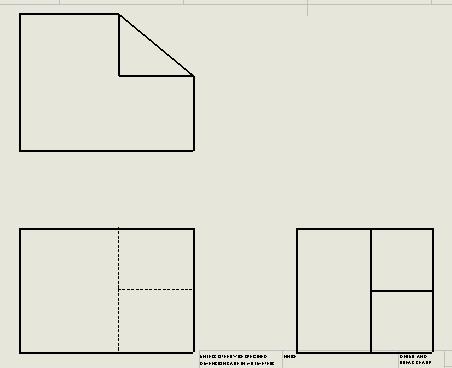
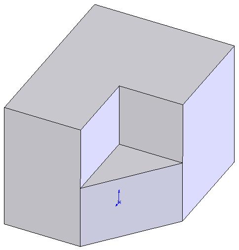
29 Advantage Multiview Drawing It represents accurate shape and size. Disadvantage Require practice in writing and reading. Example Multiviews drawing (2-view drawing) 29

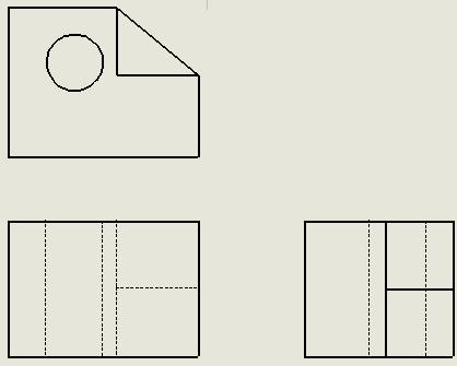
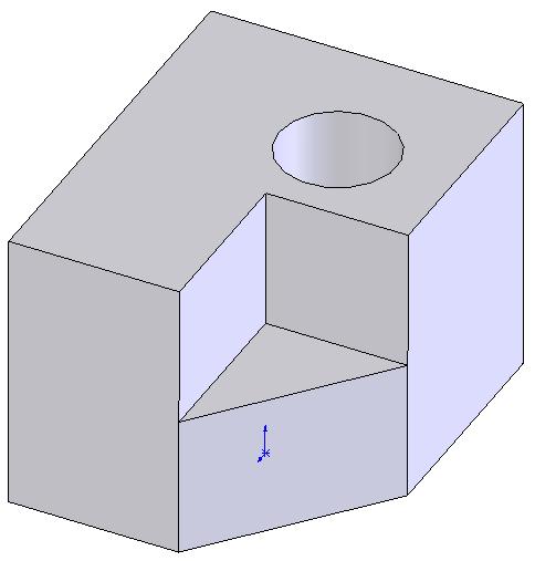
30 Axonometric (Isometric) Drawing Advantage Disadvantage Easy to understand Shape and angle distortion Example Distortions of shape and size in isometric drawing Circular hole becomes ellipse. Right angle becomes obtuse angle. 30
31 Isometric projection 31

32 ISOMETRIC PROJECTION 32

33 SECTIONAL VIEWS 33

34 AUXILIARY VIEWS Used to show true dimensions of an inclined plane. 34
35 AUXILIARY PROJECTION 35
36 AUXILIARY PROJECTION 36


37 TRADITIONAL DRAWING TOOLS
38 Drawing board/table. Drawing sheet/paper. Drafting tape. Pencils. Eraser. Sharpener. T-square. Set-squares/triangles. Scales. Compass and divider. INSTRUMENTS 38

39 DRAWING BOARD 39

40 DRAWING TABLE 40

41 DRAWING SHEET/PAPER 216 X 280 mm 280 X 382 mm 382 X 560 mm 585 X 726 mm 41

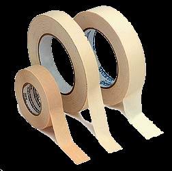

42 DRAFTING TAPE 42


43 PENCILS Wood pencils: H, 2H, 3H, 4H, 5H, 6H, 7H, 8H, 9H, B, HB, 2B, 3B, 4B, 5B, 6B. Semiautomatic Pencils (lead holder) are more convenient then ordinary wood pencils. 43
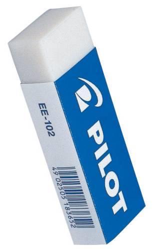

44 ERASER 44

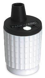
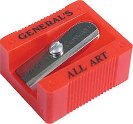
45 SHARPENER 45

46 T-SQUARE 46
47 47
48 48
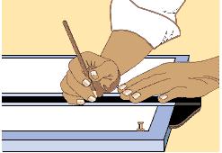
49 49
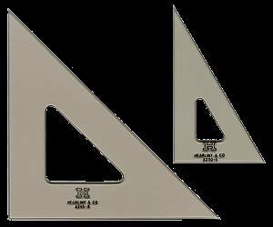
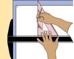
50 SET-SQUARES/TRIANGLES 50
51 51

52 CIRCLE TEMPLATE 52
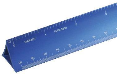
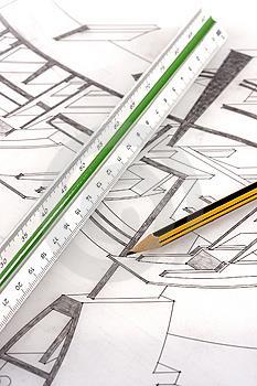
53 SCALES 53


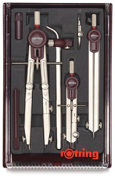
54 COMPASS AND DIVIDER 54


55 DRAWING STANDARD
56 INTRODUCTION Standards are set of rules that govern how technical drawings are represented. Drawing standards are used so that drawings convey the same meaning to everyone who reads them. 56
57 Standard Code Country Code Full name Thailand USA Japan UK Australia Germany มอก. ANSI JIS BS AS DIN ISO สำน กงำนมำตรฐำนผล ตภ ณฑ อ ตสำหกรรม American National Standard Institute Japanese Industrial Standard British Standard Australian Standard Deutsches Institut für Normung International Standards Organization 57
58 Partial List of Drawing Standards Code number JIS Z 8311 JIS Z 8312 JIS Z 8313 JIS Z 8314 JIS Z 8315 JIS Z 8316 JIS Z 8317 Contents Sizes and Format of Drawings Line Conventions Lettering Scales Projection methods Presentation of Views and Sections Dimensioning 58
59 DRAWING SHEET Trimmed paper of a size A0 ~ A4. Standard sheet size (JIS) A4 210 x 297 A3 297 x 420 A2 420 x 594 A1 594 x 841 A0 841 x 1189 (Dimensions in millimeters) A4 A3 A2 A1 A0 59
60 c c Orientation of drawing sheet 1. Type X (A0~A4) 2. Type Y (A4 only) d Border lines d Drawing space c Title block Drawing space Title block Sheet size c (min) d (min) A A A A A
61 Drawing Scales Length, size Scale is the ratio of the linear dimension of an element of an object shown in the drawing to the real linear dimension of the same element of the object. Size in drawing Actual size : 61
62 Drawing Scales Designation of a scale consists of the word SCALE followed by the indication of its ratio, as follow SCALE 1:1 for full size SCALE X:1 for enlargement scales (X > 1) SCALE 1:X for reduction scales (X > 1) Dimension numbers shown in the drawing are correspond to true size of the object and they are independent of the scale used in creating that drawing. 62
63 Basic Line Types Types of Lines Continuous thick line Continuous thin line Dash thick line Chain thin line Appearance Name according to application Visible line Dimension line Extension line Leader line Hidden line Center line NOTE : We will learn other types of line in later chapters. 63
64 Meaning of Lines Visible lines represent features that can be seen in the current view Hidden lines represent features that can not be seen in the current view Center line represents symmetry, path of motion, centers of circles, axis of axisymmetrical parts Dimension and Extension lines indicate the sizes and location of features on a drawing 64
65 TYPES OF LINE 65
66 LINE CONVENTIONS Visible Lines solid thick lines that represent visible edges or contours Hidden Lines short evenly spaced dashes that depict hidden features Section Lines solid thin lines that indicate cut surfaces Center Lines alternating long and short dashes Dimensioning Dimension Lines - solid thin lines showing dimension extent/direction Extension Lines - solid thin lines showing point or line to which dimension applies Leaders direct notes, dimensions, symbols, part numbers, etc. to features on drawing Cutting-Plane and Viewing-Plane Lines indicate location of cutting planes for sectional views and the viewing position for removed partial views Break Lines indicate only portion of object is drawn. May be random squiggled line or thin dashes joined by zigzags. Phantom Lines long thin dashes separated by pairs of short dashes indicate alternate positions of moving parts, adjacent position of related parts and repeated detail Chain Line Lines or surfaces with special requirements 66
67 Viewing-plane line 2Extension line 3Dimension Line Center Line 5Hidden Line 6Break Line Phantom 14 Line Section Line 7Cutting-plane Line 8Visible Line 9 10 Center Line (of motion) Leader SECTION 12 A-A 11 VIEW B-B 67
68 ABCDEFGHIJKLMNOPQRS TUVWXYZABCDEFGHIJKL MNOPQRSTUVWXYZABCD EF Lettering ABCDEFGHIJKLMNOPQRS TUVWXYZABCDEFGHIJKL MNOPQRSTUVWXYZABCD

69 TEXT ON DRAWINGS Text on engineering drawing is used : To communicate nongraphic information. As a substitute for graphic information, in those instance where text can communicate the needed information more clearly and quickly. Thus, it must be written with Legibility - shape - space between letters and words Uniformity - size - line thickness 69
70 Example Placement of the text on drawing Dimension & Notes Notes Title Block 70
71 LETTERING STANDARD ANSI Standard This course Use a Gothic text style, either inclined or vertical. Use all capital letters. Use 3 mm for most text height. Space between lines of text is at least 1/3 of text height. Use only a vertical Gothic text style. Use both capital and lower-case letters. Same. For letters in title block it is recommend to use 5~8 mm text height N/A. Follows ANSI rule. 71

72 BASIC STROKES Straight Slanted Horizontal Curved Examples : Application of basic stroke I letter A letter B letter

73 Suggested Strokes Sequence Upper-case letters & Numerals Straight line letters Curved line letters Curved line letters & Numerals 73

74 Suggested Strokes Sequence Lower-case letters The text s body height is about 2/3 the height of a capital letter. 74
75 STROKE SEQUENCE I L T F E H 75
76 STROKE SEQUENCE V X W 76
77 STROKE SEQUENCE N M K Z Y A 4 77
78 STROKE SEQUENCE O Q C G 78
79 STROKE SEQUENCE D U P B R J
80 STROKE SEQUENCE
81 STROKE SEQUENCE S
82 Stroke Sequence l i 82
83 Stroke Sequence v w x k z 83
84 Stroke Sequence j y f t r 84
85 Stroke Sequence c o a b d p q e 85
86 Stroke Sequence g n m h u s 86
87 Word Composition Look at the same word having different spacing between letters. A) Non-uniform spacing JIRAPONG B) Uniform spacing JIR AP O N G Which one is easier to read? 87
88 Word Composition JIRAPONG Spacing Contour \ / \ )( ) ( General conclusions are: Space between the letters depends on the contour of the letters at an adjacent side. Good spacing creates approximately equal background area between letters. 88


89 Example : Good and Poor Lettering GOOD Not uniform in style. Not uniform in height. Not uniformly vertical or inclined. Not uniform in thickness of stroke. Area between letters not uniform. Area between words not uniform. 89
90 Sentence Composition Leave the space between words equal to the space requires for writing a letter O. Example ALLODIMENSIONSOAREOIN MILLIMETERSOUNLESS OTHERWISEOSPECIFIED. 90
91 Dimensioning
92 DIMENSIONING GUIDELINES The term feature refers to surfaces, faces, holes, slots, corners, bends, arcs and fillets that add up to form an engineering part. Dimensions define the size of a feature or its location relative to other features or a frame of reference, called a datum. The basic rules of dimensioning are: 1. Dimension where the feature contour is shown; 2. Place dimensions between the views; 3. Dimension off the views; 4. Dimension mating features for assembly; 5. Do not dimension to hidden lines; 6. Stagger dimensioning values; 7. Create a logical arrangement of dimensions; 8. Consider fabrication processes and capabilities; 9. Consider inspection processes and capabilities. 92
93 93
94 IMPORTANT ELEMENTS OF DIMENSIONING Two types of dimensioning: (1) Size and location dimensions and (2) Detail dimensioning 94
95 GEOMETRICS The science of specifying and tolerancing shapes and locations of features of on objects 95
96 GEOMETRICS It is important that all persons reading a drawing interpret it exactly the same way. Parts are dimensioned based on two criteria: Basic size and locations of the features Details of construction for manufacturing Standards from ANSI (American National Standards Institute) 96
97 SCALING VS. DIMENSIONING Drawings can be a different scales, but dimensions are ALWAYS at full scale. 97
98 UNITS OF MEASURE Length English - Inches, unless otherwise stated Up to 72 inches feet and inches over SI millimeter, mm Angle degrees, minutes, seconds Angle Dimensions 98
99 ELEMENTS OF A DIMENSIONED DRAWING (BE FAMILIAR WITH THESE TERMS 99
100 ARRANGEMENT OF DIMENSIONS Keep dimension off of the part where possible. Arrange extension lines so the larger dimensions are outside of the smaller dimensi Stagger the dimension value labels to ensure they are clearly defined. 100
101 DIMENSIONING HOLES Dimension the diameter of a hole. Locate the center-line. 101 Use a notes and designators for repeated hole sizes
102 DIMENSIONING THE RADIUS OF AN ARC Dimension an arcs by its radius. Locate the center of the radius or two tangents to the arc. 102
103 DRILLED HOLES, COUNTER BORES AND COUNTERSINKS Use the depth symbol to define the depth of a drilled hole. Use the depth symbol or a section view to dimension a counter bore. Countersinks do not need a section 103 view.
104 ANGLES, CHAMFERS AND TAPERS Dimension the one vertex for an angled face, the other vertex is determined by an intersection. Chamfers are generally 45 with the width of the face specified. 104
105 ROUNDED BARS AND SLOTS The rounded end of a bar or slot has a radius that is 1/2 its width. Use R to denote this radius, do not dimension it twice. Locate the center of the arc, or the center of the slot. 105
106 DIMENSIONING STANDARDS P. 106
107 DIMENSION TEXT PLACEMENT P. 107
108 UNIDIRECTIONAL OR ALIGNED DIMENSIONING? 108
109 DUAL DIMENSIONING 109
110 DIMENSIONING BASIC SHAPES -ASSUMPTIONS Perpendicularity Assume lines that appear perpendicular to be 90 unless otherwise noted Symmetry If a part appears symmetrical it is (unless it is dimensioned otherwise) Holes in the center of a cylindrical object are automatically located 110

111 DIMENSIONING BASIC SHAPES Rectangular Prism 111


112 DIMENSIONING BASIC SHAPES Cylinders Positive Negative 112
113 DIMENSIONING BASIC SHAPES Cone Frustum 113
114 DIMENSIONING BASIC SHAPES Circle Pattern Center Lines 114
115 GROUPING DIMENSIONS Dimensions should always be placed outside the part Yes No 115
116 DIMENSION GUIDELINES Dimensions should be placed in the view that most clearly describes the feature being dimensioned (contour (shape) dimensioning) 116
117 DIMENSION GUIDELINES Maintain a minimum spacing between the object and the dimension between multiple dimensions. A visible gap shall be placed between the ends of extension lines and the feature to which they refer. 117
118 DIMENSION GUIDELINES Avoid dimensioning hidden lines. Leader lines for diameters and radius should be radial lines. 118
119 WHERE AND HOW SHOULD WE PLACE DIMENSIONS WHEN WE HAVE MANY DIMENSIONS? (CONT.) 119
120 STAGGERING DIMENSIONS Put the lesser dimensions closer to the part. Try to reference dimensions from one surface This will depend on the part and how the tolerances are based. 120
121 EXTENSION LINE PRACTICES 121
122 REPETITIVE FEATURES Use the Symbol x to Dimension Repetitive Features 122
123 SYMBOLS FOR DRILLING OPERATIONS 123
Chapter 1 Overview of an Engineering Drawing
 Chapter 1 Overview of an Engineering Drawing TOPICS Graphics language Engineering drawing Projection methods Orthographic projection Drawing standards TOPICS Traditional Drawing Tools Lettering Freehand
Chapter 1 Overview of a Technical Drawing
 Chapter 1 Overview of a Technical Drawing TOPICS Graphics language Engineering drawing Projection methods Orthographic projection Drawing standards TOPICS Traditional Drawing Tools Lettering Dimensioning
Chapter 1 Introduction
 Chapter 1 Introduction Contents Engineering drawing Drawing standards Drawing sheet Scale Lettering Line types Engineering Drawing Contents Engineering Drawing Effectiveness of Graphic Language 1. Try
Multiviews and Auxiliary Views
 Multiviews and Auxiliary Views Multiviews and Auxiliary Views Objectives Explain orthographic and multiview projection. Identifying the six principal views. Apply standard line practices to multiviews
Orthographic Projection
 Orthographic Projection Why Orthographic Projection is used in technical drawing Orthographic projection is a method of producing a number of separate two-dimensional inter-related views, which are mutually
UNIT 5a STANDARD ORTHOGRAPHIC VIEW DRAWINGS
 UNIT 5a STANDARD ORTHOGRAPHIC VIEW DRAWINGS 5.1 Introduction Orthographic views are 2D images of a 3D object obtained by viewing it from different orthogonal directions. Six principal views are possible
Chapter 2: Dimensioning Basic Topics Advanced Topics Exercises
 Chapter 2: Dimensioning Basic Topics Advanced Topics Exercises Dimensioning: Basic Topics Summary 2-1) Detailed Drawings 2-2) Learning to Dimension 2-3) Dimension Appearance and Techniques. 2-4) Dimensioning
A Concise Introduction to Engineering Graphics
 A Concise Introduction to Engineering Graphics Fourth Edition Including Worksheet Series A Timothy J. Sexton, Professor Department of Industrial Technology Ohio University BONUS Book on CD: TECHNICAL GRAPHICS
Geometric dimensioning & tolerancing (Part 1) KCEC 1101
 KCEC 1101") Geometric dimensioning & tolerancing (Part 1) KCEC 1101 Introduction Before an object can be built, complete information about both the size and shape of the object must be available. The exact shape of
Geometric dimensioning & tolerancing (Part 1) KCEC 1101 Introduction Before an object can be built, complete information about both the size and shape of the object must be available. The exact shape of
Copyrighted Material. Copyrighted Material. Copyrighted. Copyrighted. Material
 Engineering Graphics ORTHOGRAPHIC PROJECTION People who work with drawings develop the ability to look at lines on paper or on a computer screen and "see" the shapes of the objects the lines represent.
Engineering Drawing Lecture 5 PROJECTION THEORY
 University of Palestine College of Engineering & Urban Planning First Level Engineering Drawing Lecture 5 PROJECTION THEORY Lecturer: Eng. Eman Al.Swaity Eng.Heba hamad PART 1 PROJECTION METHOD TOPICS
11/12/2015 CHAPTER 7. Axonometric Drawings (cont.) Axonometric Drawings (cont.) Isometric Projections (cont.) 1) Axonometric Drawings
 Axonometric Drawings (cont.) Isometric Projections (cont.) 1) Axonometric Drawings") CHAPTER 7 1) Axonometric Drawings 1) Introduction Isometric & Oblique Projection Axonometric projection is a parallel projection technique used to create a pictorial drawing of an object by rotating the
CHAPTER 7 1) Axonometric Drawings 1) Introduction Isometric & Oblique Projection Axonometric projection is a parallel projection technique used to create a pictorial drawing of an object by rotating the
DFTG-1305 Technical Drafting Prof. Francis Ha
 DFTG-1305 Technical Drafting Prof. Francis Ha Session 5 Dimensioning Geisecke s textbook: 14 th Ed. Chapter 10 p. 362 15 th Ed. Chapter 11 p. 502 Update: 17-0508 Dimensioning Part 1 of 2 Dimensioning Summary
ENGINEERING GRAPHICS ESSENTIALS. (A Text and Lecture Aid) Second Edition. Kirstie Plantenberg University of Detroit Mercy SDC PUBLICATIONS
 Second Edition. Kirstie Plantenberg University of Detroit Mercy SDC PUBLICATIONS") ENGINEERING GRAPHICS ESSENTIALS (A Text and Lecture Aid) Second Edition Kirstie Plantenberg University of Detroit Mercy SDC PUBLICATIONS Schroff Development Corporation www.schroff.com www.schroff-europe.com
ENGINEERING GRAPHICS ESSENTIALS (A Text and Lecture Aid) Second Edition Kirstie Plantenberg University of Detroit Mercy SDC PUBLICATIONS Schroff Development Corporation www.schroff.com www.schroff-europe.com
the same information given in two different 1. Dimensions should NOT be duplicated, or Dimension Guidelines Incorrect ways.
 Dimension Guidelines 1. Dimensions should NOT be duplicated, or the same information given in two different ways. Incorrect 1. Dimensions should NOT be duplicated, or the same information given in two
(As per New Revised Syllabus of Anna University) Department of Mechanical Engineering. SATHYABAMA UNIVERSITY Jeppiaar Nagar, Chennai
 Department of Mechanical Engineering. SATHYABAMA UNIVERSITY Jeppiaar Nagar, Chennai") (1*,1((5,1* *5$3+,&6 (As per New Revised Syllabus of Anna University) Dr. S.RAMACHANDRAN, M.E., Ph.D. Professor & Head K. PANDIAN, M.E., E.V.V.RAMANAMURTHY, M.Tech., R. DEVARAJ, M.E., Associate Professors
(1*,1((5,1* *5$3+,&6 (As per New Revised Syllabus of Anna University) Dr. S.RAMACHANDRAN, M.E., Ph.D. Professor & Head K. PANDIAN, M.E., E.V.V.RAMANAMURTHY, M.Tech., R. DEVARAJ, M.E., Associate Professors
Engineering Working Drawings Basics
 Engineering Working Drawings Basics Engineering graphics is an effective way of communicating technical ideas and it is an essential tool in engineering design where most of the design process is graphically
Dimensioning. Dimensions: Are required on detail drawings. Provide the shape, size and location description: ASME Dimensioning Standards
 Dimensioning Dimensions: Are required on detail drawings. Provide the shape, size and location description: - Size dimensions - Location dimensions - Notes Local notes (specific notes) General notes ASME
Chapter 5 Pictorial sketching
 Chapter 5 Pictorial sketching Contents Freehand sketching techniques Pictorial projections - Axonometric - Oblique Isometric projection vs isometric sketch Isometric sketch from an orthographic views Isometric
Mechanical Drawing. Unit 2 Study Guide for Chapters 6-10
 Mechanical Drawing Unit 2 Study Guide for Chapters 6-10 Chapter 6 Multiview Drawing Section 6.1 Understanding Orthographic Projection A. Technical Drawing: How can a technical drawing give more accurate
DMT113 Engineering Drawing. Chapter 3 Stretch System
 DMT113 Engineering Drawing Chapter 3 Stretch System Contents Theory & Multiview Planes 6 Principle Views Multiview Sketching Technique & Perspective First & Third Angle Multiview Representations Theory
Contents. Notes on the use of this publication
 Contents Preface xxiii Scope Notes on the use of this publication xxv xxvi 1 Layout of drawings 1 1.1 General 1 1.2 Drawing sheets 1 1.3 Title block 2 1.4 Borders and frames 2 1.5 Drawing formats 2 1.6
Student Name: Teacher: Date: District: Rowan. Assessment: 9_12 T and I IC61 - Drafting I Test 1. Description: Unit C - Sketching - Test 2.
 Student Name: Teacher: Date: District: Rowan Assessment: 9_12 T and I IC61 - Drafting I Test 1 Description: Unit C - Sketching - Test 2 Form: 501 1. The most often used combination of views includes the:
ENGINEERING GRAPHICS 1.0 Introduction Engineering Graphics Drawing as an art Artist Graphic design Engineering graphics engineering drawing
 ENGINEERING GRAPHICS 1.0 Introduction Engineering is the profession in which the knowledge of mathematics and science gained by study, experience and practice is applied with good judgment to develop a
ORTHOGRAPHIC PROJECTIONS. Ms. Sicola
 ORTHOGRAPHIC PROJECTIONS Ms. Sicola Objectives List the six principal views of projection Sketch the top, front and right-side views of an object with normal, inclined, and oblique surfaces Objectives
Multiview Drawing. Definition: Graphical representation of a 3- dimensional object on one plane (sheet of paper) using two or more views.
 using two or more views.") Multiview Drawing Definition: Graphical representation of a 3- dimensional object on one plane (sheet of paper) using two or more views. Multiview Drawing Another name for multiview drawing is orthographic
Multiview Drawing Definition: Graphical representation of a 3- dimensional object on one plane (sheet of paper) using two or more views. Multiview Drawing Another name for multiview drawing is orthographic
Chapter 8. Technical Drawings
 Chapter 8 Technical Drawing Technical Drawings Multiview drawings Also called three-view drawings Simple objects take three views Front, top, one side Title block Identifies who did the design Gives date,
ENGINEERING DRAWING. 1. Set squares are used to draw different angles. What is the angel a formed by the 45⁰ set square? Give a brief answer.
 ENGINEERING DRAWING 1. Set squares are used to draw different angles. What is the angel a formed by the 45⁰ set square? Give a brief answer. 2. Which is the correct method of hatching a plane surface?
Multi-View Drawing Review
 Multi-View Drawing Review Sacramento City College EDT 300/ENGR 306 EDT 300 / ENGR 306 - Chapter 5 1 Objectives Identify and select the various views of an object. Determine the number of views needed to
ORTHOGRAPHIC PROJECTION
 ORTHOGRAPHIC PROJECTION C H A P T E R S I X OBJECTIVES 1. Recognize and the symbol for third-angle projection. 2. List the six principal views of projection. 3. Understand which views show depth in a drawing
Engineering Graphics Essentials with AutoCAD 2015 Instruction
 Kirstie Plantenberg Engineering Graphics Essentials with AutoCAD 2015 Instruction Text and Video Instruction Multimedia Disc SDC P U B L I C AT I O N S Better Textbooks. Lower Prices. www.sdcpublications.com
2003 Academic Challenge
 Worldwide Youth in Science and Engineering 2003 Academic Challenge ENGINEERING GRAPHICS TEST - SECTIONAL Engineering Graphics Test Production Team Ryan Brown, Illinois State University Author/Team Coordinator
Glass Box Projection. Gives you 6 sides to view of an object. 10/2/14 2
 2D Drawings Glass Box Projection Gives you 6 sides to view of an object. 10/2/14 2 We can simplify this for some objects to 3 views Glass Box Approach Glass Box Approach Glass Box Approach Glass Box Approach
CE 100 Civil Engineering Drawing Sessional (Lab Manual)
") CE 100 Civil Engineering Drawing Sessional (Lab Manual) Department of Civil Engineering Ahsanullah University of Science and Technology November, 2017 1 Preface This course is designed to provide civil
CE 100 Civil Engineering Drawing Sessional (Lab Manual) Department of Civil Engineering Ahsanullah University of Science and Technology November, 2017 1 Preface This course is designed to provide civil
Drawing sheet: - The various size of the drawing sheet used for engineering drawing as per IS Are listed in the table
 Dronacharya Group of Institutions, Greater Noida Computer Aided Engineering Graphics (CAEG) (NCE 151/251) List of Drawing Sheets: 1. Letter writing & Dimensioning. 2. Projection of Points & Lines. 3. Projection
ENGINEERING GRAPHICS ESSENTIALS
 ENGINEERING GRAPHICS ESSENTIALS with AutoCAD 2012 Instruction Introduction to AutoCAD Engineering Graphics Principles Hand Sketching Text and Independent Learning CD Independent Learning CD: A Comprehensive
CLASS views from detail on a grid paper. (use appropriate line types to show features) - Optional views. Turn in for grading on class 6 (06/04)
 - Optional views. Turn in for grading on class 6 (06/04)") CLASS 4 Review: - Projections - Orthographic projections Lab: - 3 views from detail on a grid paper. (use appropriate line types to show features) - Optional views. Turn in for grading on class 6 (06/04)
CLASS 4 Review: - Projections - Orthographic projections Lab: - 3 views from detail on a grid paper. (use appropriate line types to show features) - Optional views. Turn in for grading on class 6 (06/04)
Fundamentals for building Drawing
 Fundamentals for building Drawing What is Drawing Introduction Knowledge of preparing and understanding drawing will prove to be an invaluable aid while performing their jobs effectively, efficiently.
ENGINEERING GRAPHICS ESSENTIALS
 ENGINEERING GRAPHICS ESSENTIALS Text and Digital Learning KIRSTIE PLANTENBERG FIFTH EDITION SDC P U B L I C AT I O N S Better Textbooks. Lower Prices. www.sdcpublications.com ACCESS CODE UNIQUE CODE INSIDE
Technological Design Mr. Wadowski. Orthographic & Isometric Drawing Lesson
 Technological Design Mr. Wadowski Orthographic & Isometric Drawing Lesson TOPICS Working Drawings, Isometric Drawings & Orthographic Drawings Glass box concept Multiview projection Orthographic projection
Study Unit. Auxiliary Views. This sneak preview of your study material has been prepared in advance of the book's actual online release.
 Study Unit Auxiliary Views This sneak preview of your study material has been prepared in advance of the book's actual online release. iii Preview You re entering now into another subject area in your
Brief Introduction to Engineering Graphics The use of drawings to convey information. Sketching freehand straight edge
 Brief Introduction to Engineering Graphics The use of drawings to convey information. Sketching freehand straight edge CAD drawings 2D drafting 3D model to 2D drawings 1 Different Graphical Representation
1 st Subject: Types and Conventions of Dimensions and Notes
 Beginning Engineering Graphics 7 th Week Lecture Notes Instructor: Edward N. Locke Topic: Dimensions, Tolerances, Graphs and Charts 1 st Subject: Types and Conventions of Dimensions and Notes A. Definitions
Sketching in SciTech. What you need to know for graphic communication
 Sketching in SciTech What you need to know for graphic communication Sketching in your Logbook Use pencil Take up the WHOLE PAGE Label things 1. Proportion Each part of the sketch is the right size,
Isometric Drawing Chapter 26
 Isometric Drawing Chapter 26 Sacramento City College EDT 310 EDT 310 - Chapter 26 - Isometric Drawing 1 Drawing Types Pictorial Drawing types: Perspective Orthographic Isometric Oblique Pictorial - like
Civil Engineering Drawing
 Civil Engineering Drawing Third Angle Projection In third angle projection, front view is always drawn at the bottom, top view just above the front view, and end view, is drawn on that side of the front
Chapter 5 Pictorial Projection
 Chapter 5 Pictorial Projection Objectives After completing this chapter, the students will be able to Create freehand sketches using the correct sketching techniques. Explainthe difference between axonometric
Dimensioning 2-4) Dimensioning and Locating Simple Features
 Dimensioning and Locating Simple Features") Dimensioning 2-4) Dimensioning and Locating Simple Features Dimensioning Features a) A circle is dimensioned by its diameter and an arc by its radius using a leader line and a note. Exercise 2-6 Circular
Dimensioning 2-4) Dimensioning and Locating Simple Features Dimensioning Features a) A circle is dimensioned by its diameter and an arc by its radius using a leader line and a note. Exercise 2-6 Circular
ME1105 Engineering Drawing & Design
 City University London Term 1 Assessment 2008/2009 School of Engineering and Mathematical Sciences ME1105 Engineering Drawing & Design Student Name:.., Group: Examination duration: Reading time: This paper
Engineering Graphics, Class 8 Orthographic Projection. Mohammad I. Kilani. Mechanical Engineering Department University of Jordan
 Engineering Graphics, Class 8 Orthographic Projection Mohammad I. Kilani Mechanical Engineering Department University of Jordan Multi view drawings Multi view drawings provide accurate shape descriptions
MULTIPLE CHOICE QUESTIONS - CHAPTER 6
 MULTIPLE CHOICE QUESTIONS - CHAPTER 6 1. The selection of the front view in executing a multiview drawing of an object is dependent upon the following factors: a. size and shape of the object and their
Elementary Dimensioning
 Elementary Dimensioning Standards Institutions ANSI - American National Standards Institute - creates the engineering standards for North America. ISO - International Organization for Standardization -
Multiview Projection
 DFTG-1305 Technical Drafting Prof. Francis Ha Session 4 Multiview Projection (or Orthographic Projection) Reading: Geisecke s textbook: 14 th Ed. Chapter 5 p.162 15 th Ed. Chapter 6 p.232 Update: 17-0510
Guide To British Standards
 Guide To British Standards Higher Graphic Communication C O N T E N T S page TITLE BLOCK 2 DRAWING SCALES 2 LINE TYPES 3 ORTHOGRAPHIC PROJECTION 4 SECTIONAL VIEWS 4 SCREW THREADS & COMPONENTS 7 INTERUPTTED
ENGINEERING GRAPHICS ESSENTIALS
 ENGINEERING GRAPHICS ESSENTIALS with AutoCAD 2012 Instruction Introduction to AutoCAD Engineering Graphics Principles Hand Sketching Text and Independent Learning CD Independent Learning CD: A Comprehensive
2010 Academic Challenge
 2010 Academic Challenge ENGINEERING GRAPHICS TEST STATE FINALS This Test Consists of 40 Questions Engineering Graphics Test Production Team Ryan K. Brown, Illinois State University Author/Team Leader Jacob
PROJECTIONS PARALLEL CONICAL PROJECTIONS PROJECTIONS OBLIQUE ORTHOGRAPHIC PROJECTIONS PROJECTIONS
 PROJECTIONS CONICAL PROJECTIONS PARALLEL PROJECTIONS OBLIQUE PROJECTIONS ORTHOGRAPHIC PROJECTIONS ISOMETRIC MULTI-VIEW an object; The Description of Forms Behind every drawing of an object is space relationship
Student Name: Teacher: Date: District: Rowan. Assessment: 9_12 T and I IC61 - Drafting I Test 2. Description: Drafting 1 - Test 6.
 Student Name: Teacher: Date: District: Rowan Assessment: 9_12 T and I IC61 - Drafting I Test 2 Description: Drafting 1 - Test 6 Form: 501 1. 2X on a hole note means: A. Double the size of the hole. B.
2003 Academic Challenge
 Worldwide Youth in Science and Engineering 2003 Academic Challenge ENGINEERING GRAPHICS TEST - REGIONAL Engineering Graphics Test Production Team Ryan Brown, Illinois State University Author/Team Coordinator
ENGINEERING DRAWING. UNIT III - Part A
 DEVELOPMENT OF SURFACES: ENGINEERING DRAWING UNIT III - Part A 1. What is meant by development of surfaces? 2. Development of surfaces of an object is also known as flat pattern of the object. (True/ False)
DELHI TECHNOLOGICAL UNIVERSITY ENGINEERING GRAPHICS LAB MANUAL
 DELHI TECHNOLOGICAL UNIVERSITY ENGINEERING GRAPHICS LAB MANUAL NAME: - ROLL NO: - GROUP: - BRANCH: - GROUP TEACHER: Page 1 www.rooplalrana.com 1 GENERAL INSTRUCTIONS FOR ENGG. GRAPHICS LAB 1) Students
Graphical Communication
 Chapter 9 Graphical Communication mmm Becoming a fully competent engineer is a long yet rewarding process that requires the acquisition of many diverse skills and a wide body of knowledge. Learning most
Production drawing Diagram. a) I am a freehand drawing that follows technical drawing standards.
 I am a freehand drawing that follows technical drawing standards.") THE TECHNOLOGICAL WORLD Graphical language STUDENT BOOK Ch. 11, pp. 336 342 Basic lines, geometric lines, sketches 1. In technology, the two most widely used types of technical drawings are: a) sketch
THE TECHNOLOGICAL WORLD Graphical language STUDENT BOOK Ch. 11, pp. 336 342 Basic lines, geometric lines, sketches 1. In technology, the two most widely used types of technical drawings are: a) sketch
3. The dimensioning SYMBOLS for arcs and circles should be given:
 Draft Student Name: Teacher: District: Date: Wake County Test: 9_12 T and I IC61 - Drafting I Test 2 Description: 4.08 Dimensioning Form: 501 1. The MINIMUM amount of space between two, ADJACENT DIMENSION
Geometric Tolerances & Dimensioning
 Geometric Tolerances & Dimensioning MANUFACTURING PROCESSES - 2, IE-352 Ahmed M. El-Sherbeeny, PhD KING SAUD UNIVERSITY Spring - 2015 1 Content Overview Form tolerances Orientation tolerances Location
ENGINEERING GRAPHICS 1E9
 Lecture 3 Monday, 15 December 2014 1 ENGINEERING GRAPHICS 1E9 Lecture 3: Isometric Projections Lecture 3 Monday, 15 December 2014 2 What is ISOMETRIC? It is a method of producing pictorial view of an object
technical drawing
 technical drawing school of art, design and architecture nust spring 2011 http://www.youtube.com/watch?v=q6mk9hpxwvo http://www.youtube.com/watch?v=bnu2gb7w4qs Objective abstraction - axonometric view
Geometric Dimensioning and Tolerancing
 Geometric Dimensioning and Tolerancing (Known as GDT) What is GDT Helps ensure interchangeability of parts. Use is dictated by function and relationship of the part feature. It does not take the place
DFTG-1305 Technical Drafting Prof. Francis Ha
 DFTG-1305 Technical Drafting Prof. Francis Ha Session 4 Orthographic Projection (or Multiview Projection) Reading: Geisecke s textbook: 14 th Ed. Chapter 5 p.162 15 th Ed. Chapter 6 p.232 Update: 18-0205
1. is the modification of an existing product or process. A. Invention C. Recreation B. Innovation D. Enhancement
 Introduction to Engineering Design Lewis-Palmer School District #38, Monument, Colorado Fall Semester 2008 Final Exam 1. is the modification of an existing product or process. A. Invention C. Recreation
Pictorial Drawings. DFTG-1305 Technical Drafting Prepared by Francis Ha, Instructor
 DFTG-1305 Technical Drafting Prepared by Francis Ha, Instructor Pictorial Drawings Geisecke s textbook for reference: 14 th Ed. Ch. 15: p. 601 Ch. 16: p. 620 15 th Ed. Ch. 14: p. 518 Ch. 15: p. 552 Update:
GL5: Visualisation and reading drawings
 436-105 Engineering Communications GL5:1 GL5: Visualisation and reading drawings Being able to both: represent a 3D object in multiview drawings interpret a multiview drawing to visualise a 3D object is
ME 111: Engineering Drawing
 ME 111: Engineering Drawing Lecture # 01 Introduction For more detail, visit http://shilloi.iitg.ernet.in/~psr/ Indian Institute of Technology Guwahati Guwahati 781039 1 Syllabus 1. Importance of engineering
Philadelphia University Faculty of Engineering Mechanical Engineering Department
 Philadelphia University Faculty of Engineering Mechanical Engineering Department Basics of Engineering Drawing Manual Done by:- Eng. Laith R.I. Batarseh Eng. Hanan Khamis 2017 1 Table of contents SUBJECT
GOVERNMENT POLYTECHNIC, VALSAD MECHANICAL ENGINEERING DEPARTMENT ASSIGNMENT SUB: MECHANICAL DRAFTING (C321901) TERM:172
 TERM:172") GOVERNMENT POLYTECHNIC, VALSAD MECHANICAL ENGINEERING DEPARTMENT ASSIGNMENT SUB: MECHANICAL DRAFTING (C321901) TERM:172 1) When all the dimension are placed above the dimension line, it is called (a) Aligned
GOVERNMENT POLYTECHNIC, VALSAD MECHANICAL ENGINEERING DEPARTMENT ASSIGNMENT SUB: MECHANICAL DRAFTING (C321901) TERM:172 1) When all the dimension are placed above the dimension line, it is called (a) Aligned
GE ENGINEERING GRAPHICS
 ANNA UNIVERSITY, CHENNAI (REGULATION GE8152 - ENGINEERING GRAPHICS B.E SEMESTER I Lecture Tutorial Practical Marks Credits Total Hours 2 0 3 100 4 90 Mr.S.Gokul (Asst. Prof/Mech) Sri Eshwar College of
2009 Academic Challenge
 2009 Academic Challenge ENGINEERING GRAPHICS TEST STATE FINALS This Test Consists of 50 Questions Engineering Graphics Test Production Team Ryan Brown, Illinois State University Author/Team Leader Kevin
AutoCAD Tutor 2011 Support Docs
 AutoCAD Tutor 2011 Support Docs CHAPTER 1 CUSTOMIZING THE QUICK ACCESS TOOLBAR One of the advantages of the Quick Access Toolbar is the ability to display the AutoCAD commands that you frequently use.
DWG 002. Blueprint Reading. Geometric Terminology Orthographic Projection. Instructor Guide
 DWG 002 Blueprint Reading Geometric Terminology Orthographic Projection Instructor Guide Introduction Module Purpose The purpose of the Blueprint Reading modules is to introduce students to production
CAD Mechanical Design I
 EXAM INFORMATION Items 58 Points 85 Prerequisites NONE Course Length ONE SEMESTER Career Cluster ARCHITECTURE AND CONSTRUCTION MANUFACTURING SCIENCE, TECHNOLOGY, ENGINEERING AND MATHEMATICS Performance
2004 Academic Challenge
 2004 Academic Challenge ENGINEERING GRAPHICS TEST - REGIONAL Engineering Graphics Test Production Team Ryan Brown, Illinois State University Author/Team Coordinator Kevin Devine, Illinois State University
Unit-5 ISOMETRIC PROJECTION
 Unit-5 ISOMETRIC PROJECTION Importance Points in Isometric: 1. For drawing the isometric, the object must be viewed such that either the front -right or the left edges becomes nearest. 2. All vertical
ORTHOGRAPHIC PROJECTION
 ORTHOGRAPHIC PROJECTION INTRODUCTION Any object has three dimensions, that is, length, width and thickness. A projection is defined as a representation of an object on a two dimensional plane. The projections
TECHNICAL DESIGN I (540)
") DESCRIPTION The first assessment in a series, Technical Design I prepares students to develop technical knowledge and skills required to plan and prepare scale pictorial interpretations of engineering
DESCRIPTION The first assessment in a series, Technical Design I prepares students to develop technical knowledge and skills required to plan and prepare scale pictorial interpretations of engineering
DIMENSIONING ENGINEERING DRAWINGS
 DIMENSIONING ENGINEERING DRAWINGS An engineering drawing must be properly dimensioned in order to convey the designer s intent to the end user. Dimensions provide the information needed to specify the
2007 Academic Challenge
 2007 Academic Challenge ENGINEERING GRAPHICS TEST - STATE FINALS This Test Consists of 50 Questions Engineering Graphics Test Production Team Ryan Brown, Illinois State University Author/Team Coordinator
Interpretation of Drawings. An Introduction to the Basic Concepts of Creating Technical Drawings
 Interpretation of Drawings An Introduction to the Basic Concepts of Creating Technical Drawings Introduction In the design process drawings are the main way in which information about an object or product
At the conclusion of this unit you should be able to accomplish the following with a 70% accuracy
 7 Multiview Drawing OBJECTIVES At the conclusion of this unit you should be able to accomplish the following with a 70% accuracy 1. explain the importance of mulitview drawing as a communication tool far
SOLIDWORKS 2015 and Engineering Graphics
 SOLIDWORKS 2015 and Engineering Graphics An Integrated Approach Randy H. Shih SDC PUBLICATIONS Better Textbooks. Lower Prices. www.sdcpublications.com Powered by TCPDF (www.tcpdf.org) Visit the following
Chapter 6. Architectural Lines and Lettering
 Chapter 6 Architectural Lines and Lettering Drafting Introduction Universal graphic language Uses lines, symbols, dimensions, and notes to describe a structure to be built Properly drawn lines are dark,
Part 1: General principles
 Provläsningsexemplar / Preview INTERNATIONAL STANDARD ISO 129-1 Second edition 2018-02 Technical product documentation (TPD) Presentation of dimensions and tolerances Part 1: General principles Documentation
2009 Academic Challenge
 2009 Academic Challenge ENGINEERING GRAPHICS TEST SECTIONAL This Test Consists of 50 Questions Engineering Graphics Test Production Team Ryan Brown, Illinois State University Author/Team Leader Kevin Devine,
Engineering Graphics & Technology. NQF Level 2. Sparrow Consulting LECTURER S GUIDE TVET FIRST
 Engineering Graphics & Technology NQF Level 2 Sparrow Consulting LECTURER S GUIDE TVET FIRST Engineering Graphics & Technology NQF Level 2 Lecturer s Guide M Conradie Engineering Graphics & Technology
and Engineering Graphics
 SOLIDWORKS 2018 and Engineering Graphics An Integrated Approach Randy H. Shih SDC PUBLICATIONS Better Textbooks. Lower Prices. www.sdcpublications.com Powered by TCPDF (www.tcpdf.org) Visit the following
ENGINEERING GRAPHICS UNIT V ISOMETRIC PROJECTION PERSPECTIVE PROJECTION
 ENGINEERING GRAPHICS UNIT V ISOMETRIC PROJECTION PERSPECTIVE PROJECTION 1.PICTORIAL PROJECTIONS To visualize the shape of the whole object in its 3- D form, all the two or three orthographic views of the
2001 Academic Challenge
 Worldwide Youth in Science and Engineering 2001 Academic Challenge ENGINEERING GRAPHICS TEST - STATE FINALS GENERAL DIRECTIONS Engineering Graphics Test Production Team Ralph Dirksen, Western Illinois
Activity 5.2 Making Sketches in CAD
 Activity 5.2 Making Sketches in CAD Introduction It would be great if computer systems were advanced enough to take a mental image of an object, such as the thought of a sports car, and instantly generate
Standards for Your Career Field
 Dimensioning Dimensions Dimensions are used to describe the sizes and relationships between features in your drawing. Dimensions are used to manufacture parts and to inspect the resulting parts to determine
Downloaded from ENGINEERING DRAWING. Time allowed : 3 hours Maximum Marks : 70
 ENGINEERING DRAWING Time allowed : 3 hours Maximum Marks : 70 Note : (i) (ii) Attempt all the questions. Use both sides of the drawing sheet, if necessary. (iii) All dimensions are in millimeters. (iv)
Engineering Graphics. Class 2 Drafting Instruments Mohammad Kilani
 Engineering Graphics Class 2 Drafting Instruments Mohammad Kilani Drafting Instruments A Design is as good as its instruments A engineering drawing is a highly stylized graphic representation of an idea.