Downloaded from ENGINEERING DRAWING. Time allowed : 3 hours Maximum Marks : 70
|
|
|
- Everett Nicholson
- 5 years ago
- Views:
Transcription
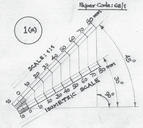
1 ENGINEERING DRAWING Time allowed : 3 hours Maximum Marks : 70 Note : (i) (ii) Attempt all the questions. Use both sides of the drawing sheet, if necessary. (iii) All dimensions are in millimeters. (iv) Missing and mismatching dimensions, if any, may be suitably assumed. (v) Follow the SP : codes (with First Angle method of projection). (vi) In no view of questions 1 and in no sectioned view of question 3, are hidden edges / lines required. QUESTION PAPER CODE 68/1 1. (a) Construct an isometric scale, 90 mm long. 4 (b) (c) Construct the isometric projection, to isometric scale, of a pentagonal pyramid (base edge = 40 mm and height = 90 mm), keeping it in the inverted position. The axis is perpendicular to H.P. One of its base edges is parallel to V.P. and away from that. Draw the axis and indicate the direction of viewing. Give all dimensions. 8 A cone (diameter = 40 mm and height = 60 mm) is placed, centrally, with its base on the hexagonal face of a hexagonal prism (base edge = 40 mm and height = 25 mm). The common axis is perpendicular to H.P. The base of the prism is on H.P., and one of the base edges is perpendicular to V.P. Draw the isometric projection of the solids, placed together, to isometric scale. Draw the common axis and indicate the direction of viewing. Give all dimensions
2 2. (a) Draw to scale 1 : 1, the standard profile of a metric thread (internal), taking enlarged pitch = 40 mm. Give standard dimensions. 9 OR Draw to scale 1 : 1, the. front view and top view of a Tee bolt of size M 20. Keep the axis vertical. Give standard dimensions. (b) Sketch freehand the front view and top view of a grub screw of size M 25. Keep the axis vertical. Give standard dimensions. 6 OR Sketch freehand the front view and the top view of a pan head rivet, shank diameter = 20 mm. Keep the axis vertical. Give standard dimensions. 3. Fig. 1 shows the details of a Plummer block. Assemble the parts correctly and draw, to scale 1 : 1, the front view, right half in section. 24 Print title and scale used. Give 8 important dimensions. 6 Figure 1 409
3 Fig. 2 shows, partly, the assembly of a flanged pipe joint. Disassemble the parts and then draw the following views, to scale 1 : 1. Keep the same position of the parts with respect to H.P. and V.P. : (a) (b) Front view of the flange A, showing the top half in section and side view, as seen from the left. 16 Front view of any hexagonal nut and the side view, as seen from the right. Print titles of both and scale used. 8 Draw the projection symbol. Give 8 important dimensions. 6 Figure
4 QUESTION PAPER CODE (a) Construct an isometric scale 80 mm long. 4 (b) Construct the isometric projection, to isometric scale, of a hexagonal pyramid (base edge = 30 mm and height = 80 mm) keeping it in the inverted position. The axis is perpendicular to H.P. One base edge is perpendicular to V.P. Draw the axis and indicate the direction of viewing. Give all dimensions. 7 (c) A cylinder (diameter = 50 mm and height = 70 mm) is placed, centrally, with its circular end on the pentagonal face of a pentagonal prism (base edge = 40 mm and height = 30 mm). The common axis is perpendicular to H.P. The base of the prism is on H.P. and one of its base edges is parallel to V.P. and away from it. Draw the isometric projection of the solids, placed together, to isometric scale. Draw the common axis and indicate the direction of viewing. Give all dimensions (a) Draw to scale 1:1 the standard profile of a B.S.W. thread, taking enlarged pitch = 50 mm. Give all standard dimensions. 9 OR Draw the full sectional front view and top view of a single riveted lap joint. Take plate thickness = 9 mm. Give all standard dimensions. Use scale 1 : 1. (b) Sketch free-hand the front view and top view of a 90 flat counter sunk head screw of size M 20, keeping the axis vertical. Give all standard dimensions. 6 OR Sketch free-hand the front view, top view and side view of a Woodruff key for a shaft of 60 mm diameter. Give all standard dimensions. 3. Figure 1, shows the details of a knuckle joint. Assemble the parts correctly and then draw, to scale 1 : 1, the front view, lower half in section. 24 Print title and scale used. Give 8 important dimensions
5 OR Figure 2, shows the assembly of an open bearing. Disassemble the base and the bush and draw the following views to scale 1 : 1. Keep the same positions of the base and the bush with respect to H.P. and V.P. (a) Front view of the base, showing right half in section, and its top View. 16 (b) Front view of the bush and full sectional side view, as seen from the left side. 8 Print titles of both and scale used. Draw the projection symbol. Give 8 important dimensions
6 413
7 Marking Scheme Engineering Drawing Notes: (i) (ii) (iii) (iv) (v) Marks are to be awarded in proportion to the work done. Mistakes in dimensioning up to ± 1.0 mm may be ignored. In dimensioning, arrow heads of various types, as per SP , are usable. However, where space is too small for an arrowhead, oblique stroke or a dot may be employed. In no view of questions 1 and in no sectioned view of question 3, are hidden edges/lines required. Other standard methods of drawing/proportions for features like nuts, heads of bolts, screws etc., employed by examinees, may also be accepted. All Questions are to be answered correctly and accurately. QUESTION PAPER CODE 68/1 EXPECTED ANSWERS/VALUE POINTS Q.1 ISOMETRIC SCALE (4) (a) (i) Marking of divisions of 10 mm, 1 mm on true scale and marking angles of 30 & (ii) Projections from scale 1:1 to get points on Isometric scale. ½ (iii) Construction of Isometric scale with main divisions of 10 mm each. 1 (iv) Division of the first part into 10 sub-divisions. 1 (v) Printing Scale 1:1 and Isometric Scale ½ (b) ISOMETRIC PROJECTION OF AN INVERTED PENTAGONAL PYRAMID (8) (i) Helping view (with isometric scale or scale 1:1) of pentagon with a side, parallel to V.P. and away from it. 1 (ii) Drawing isometric pentagon on top. 3 (iii) Drawing slant edges. 1½ 414
8 (iv) Marking the axis 1 (v) Two dimensions, including that of axis through in-centers 1 (vi) Direction of viewing ½ Note: For incorrect position of the pyramid, like using the 40mm sides of the pentagon for the base, 1 ½ marks should be deducted. If axis is drawn perpendicular to V.P. instead of drawing perpendicular to H.P., as asked, 1½ marks should be deducted. Also, in the helping view, if a side of pentagon is not taken parallel to V.P. and away from it, 1 mark (½ + ½) should be deducted. (c) CONE PLACED, CENTRALLY, ON A HEXAGONAL PRISM. (13) (A) HEXAGONAL PRISM (7) (i) Helping view of hexagon with a side perpendicular to V.P. 1 (ii) Drawing isometric hexagons 3 (iii) Drawing face edges, parallel to vertical axis/v.p. 2 (iv) Dimensioning the edge of the base and axis, i.e. height of prism. 1 (B) CONE AND DIRECTION OF VIEWING (6) (i) Drawing elliptical curve for base 2½ (ii) Drawing tangents to curves, i.e. generators 1 (iii) Indicating the common axis of two solids 1 (iv) Dimensioning of diameter and axis 1 (v) Direction of viewing ½ Note: For incorrectly placed solids, etc., proportionate deductions, as proposed in Q.1 (b) may be used. Q.2 (a) METRIC SCREW THREAD PROFILE (INTERNAL) (9) (i) Distance, equal to pitch, marked correctly and angles of 60, drawn correctly 2 (ii) Flat edges and curves for threads (minimum 2), drawn correctly 2½ (iii) Side edges (flanks), drawn correctly 1½ (iv) Dimensioning 2 415
9 (v) Neatness and line work 1 OR TEE BOLT (9) FRONT VIEW (i) Threaded and unthreaded portions of cylindrical shank, square neck and center line. 2½ (ii) Head of bolt 1½ TOP VIEW (i) Circles of diameter d and 0.85 d (thin and broken) 1 (ii) Square neck and rest of the portion 1½ Details: (i) Dimensioning 1½ (ii) Neatness and line work 1 Note: 3 marks may be deducted, in all, if sketched freehand, instead of drawing to scale 1:1. Q.2 (b) FOLLOWING COMPONENTS ARE TO BE SKETCHED FREEHAND PROPORTIONATELY: GRUB SCREW (SIZE M25) (6) (i) Front view with its axis, perpendicular to H.P. 3 (ii) Top view 2 (iii) Dimensions 1 OR PAN HEAD RIVET (for a diameter of rivet of 25 mm) (6) FRONT VIEW (i) Sketching the head with correct proportions. 2½ (ii) Sketching cylindrical portion, broken end and hatching 1½ 416
10 TOP VIEW (i) Two circles 1 (ii) Dimensioning 1 Note: 2 marks may be deducted, if these components are drawn with instruments, instead of being sketched freehand. Q.3 PLUMMER BLOCK (Assembly) (30) (A) FRONT VIEW, RIGHT HALF IN SECTION (15) (i) Base: (a) Right half in section with two holes with their axes. 4½ (b) Left half, without section, with properly located axes for holes. 2½ (ii) Brasses (Upper & lower): (a) Drawn in correct position with right half in section alongwith oil hole and snug. 3 (b) Left half without section 2 (iii) Cap: (a) Right half in section with holes for bolt and oil. 3 (b) Left half without section. 1½ (iv) Square headed bolts: (a) Full bolt on the right. 3 (b) End of bolt, coming out of nut, on the left, alongwith shank between the base and the cap. 1½ (v) Hexagonal nuts: One nut, placed properly, on each side 3 (B) DETAILS:- (6) (i) Neatness and line work. 2 (ii) Printing title and scale used 2 (iii) Showing 8 dimensions 2 OR 417
11 FLANGED PIPE JOINT (Dis-assembly) (30) (A) FLANGE A (16) FRONT VIEW, TOP HALF IN SECTION (i) Boundary with conventional representation of end of pipe 3½ (ii) Properly located axes of pipe and two holes for bolts 1½ (iii) Line indicating inner radius of pipe, hatching lines and holes 3 (iv) Remaining two vertical lines in lower half 1 SIDE VIEW, AS SEEN FROM THE LEFT (i) Four circles, axes and the hatching lines 3 (ii) Drawing four holes for bolts and the pitch circle 2½ (iii) Drawing cutting plane XX for the front view ½ (iv) Neatness and line work 1 (B) HEXAGONAL NUT FRONT VIEW (8) (i) Drawing horizontal axis, one vertical line for base of nut and four horizontal lines 1½ (ii) Drawing curves for chamfer of nut, the associated vertical line and chamfer lines 2 SIDE VIEW, AS SEEN FROM THE RIGHT (i) Drawing the chamfer circle, two circles one broken and other full and the circumscribing hexagon. 3 (ii) Drawing the horizontal and the vertical axis. ½ (iii) Neatness and line work 1 DETAILS (6) (i) Printing titles 2 (ii) Projection symbol 1 (iii) Scale used 1 (iv) Dimensioning 2 418
12 419
13 420
14 421
15 422
16 423
17 424
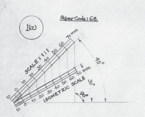
18 QUESTION PAPER CODE 68 EXPECTED ANSWERS/VALUE POINTS Q.1 (a) ISOMETRIC SCALE (4) (i) Marking of divisions of 10 mm, 1 mm on true scale and marking angles of 30 & (ii) Projections from scale 1:1 to get points on Isometric scale. ½ (iii) Construction of Isometric scale with main divisions of 10 mm each. 1 (iv) Division of the first part into 10 sub-divisions. 1 (v) Printing Scale 1:1 and Isometric Scale ½ (b) ISOMETRIC PROJECTION OF AN INVERTED HEXAGONAL PYRAMID (7) (i) Helping view(with isometric scale or scale 1:1) of hexagon with a side, perpendicular to V.P. 1 (ii) Drawing isometric hexagon on top 2 ½ (iii) Drawing slant edges 1 ½ (iv) Marking the axis and direction of viewing 1 (v) Two dimensions, including that axis through in-centres 1 Note:- For incorrect position of the pyramid, like using the 30mm sides of the hexagon for the base, 1½ marks should be deducted if axis is drawn perpendicular to V.P., instead of drawing perpendicular to H.P., as asked, 1½ should be deducted, Also, in the helping view, if a side of hexagon is not taken perpendicular to V.P., as asked, 1mark should be deducted. (c) CYLINDER, PLACED, CENTRALLY, ON PENTAGONAL PRISM: (14) PENTAGONAL PRISM: (i) Helping view (with isometric scale or scale 1:1) of pentagon with a side, parallel to V.P. and away from it. 1 (ii) Drawing isometric pentagons at the top and bottom 3 (iii) Drawing face edges parallel to axis. 1½ (iv) Dimensioning (base side and height) 1 425
19 CYLINDER:- (i) Correct central placement and drawing common vertical axis. 1½ (ii) Drawing ellipses for top and base. 3 (iii) Drawing to tangents to ellipses 1 (iv) Dimensioning diameter and axis through in centres 1 (v) Neatness and line work 1 Note: For incorrectly placed solids etc. proportionate deductions, as proposed in Q.1 (b) may be used. Q.2 (a) B.S.W. THREAD PROFILE (9) (i) Distances, equal to pitch, marked correctly and angles 55 drawn correctly. 2 (ii) Curves for threads ( minimum 2 curves at the top and bottom ) 2 (iii) Side edges ( flanks), tangential to the curves 2 (iv) Dimensioning 2 (v) Neatness and line work 1 OR SINGLE RIVETED LAP JOINT (9) SECTIONAL FRONT VIEW (i) Plates with hatching line 2 (ii) Rivet with both head 2 TOP VIEW (i) Two plates correctly positioned. 1 (ii) Rivet heads (minimum 2) with correct pitch length and their axes along with Cutting plane line 2 (iii) Dimensioning, neatness and line work. 2 Note: 3 marks may be deducted, in all, if sketched freehand, Instead of drawings to scale 1:1 426
20 Q.2 (b) 90 FLAT COUNTER SUNK HEAD SCREEN (6) (i) Sketching front view with its axis, perpendicular to HP 3 (ii) Sketching top view. 2 (iii) Dimensioning 1 WOOD RUFF KEY OR (i) In front view, keeping horizontal edge at 0.25 t below the centre 1 (ii) Drawing the horizontal edge and curve with a radius of R = 2t 2 (iii) Drawing side view 1 (iv) Drawing top view 1 (v) Dimensioning 1 Note: 2 marks may be deducted if these components are drawn with instruments, instead of being sketched free hand. Q.3 KNUCKLE JOINT (Assembly): (30) FRONT VIEW, LOWER HALF IN SECTION: (24) (i) Fork (complete), with lower half in section. 9 (ii) Single eye end (complete), with lower half in section, positioned correctly 5 (iii) Knuckle pin (fitted) and positioned correctly. 3 (iv) Collar, positioned correctly, with hatching lines. 2 (v) Taper pin, positioned correctly. 3 (vi) Neatness and line work. 2 Printing title (1), scale used (1) and eight dimensions (4) (6) (OR) OPEN BEARING (Disassembly) (30) (A) BASE: FRONT VIEW, RIGHT HALF IN SECTION (16) (i) Full boundary of base along with properly located axes (four in all) and all the fillets and rounds
21 (ii) For right half sectioned portion of the base, hatching lines, hole and base recess 3 TOP VIEW (i) Complete boundary with four vertical lines and dotted rectangle (indicating recess) 3½ (ii) Two bolt holes and cutting plane lines 2½ (iii) Neatness and line work. 1 BUSH (8) FRONT VIEW (i) Six vertical lines 1½ (ii) Three semi circles and cutting plane line 2 SIDE VIEW (FULL IN SECTION) (i) Drawing entire boundary 2 (ii) Horizontal dark line for R20, axis and hatching lines 1½ (iii) Neatness and line work 1 DETAILS (6) Titles of both (2), scale used (1), projection symbol (1) and eight dimensions (2) 428
22 429
23 430
24 431
25 432
26 433
27 434
28 435
ENGINEERING GRAPHICS
 ENGINEERING GRAPHICS Time allowed : 3 hours Maximum Marks : 70 Note : (ii) Attempt all the questions. Use both sides of the drawing sheet, if necessary. (iii) All dimensions are in millimetres. (iv) Missing
Marking Scheme Engineering Graphics
 Marking Scheme Engineering Graphics All Questions are to be answered correctly and accurately. General Note: (i) (ii) (iii) (iv) (v) Marks are to be awarded in proportion to the work done. Mistakes in
ENGINEERING GRAPHICS
 ENGINEERING GRAPHICS CLASS - XII (046) DESIGN OF THE QUESTION PAPER Time : 3 Hrs Max. Marks : 70 The weightage of the distribution of marks over different contents of the question paper shall be as follows:
SAMPLE QUESTION PAPER III ENGINEERING GRAPHICS (046) Time Allowed: 3 hours Maximum Marks: 70
 Time Allowed: 3 hours Maximum Marks: 70") SAMPLE QUESTION PAPER III ENGINEERING GRAPHICS (046) Time Allowed: 3 hours Maximum Marks: 70 Note: (i) Attempt all the questions. (ii) Use both sides of the drawing sheet, if necessary. (iii) All dimensions
SAMPLE QUESTION PAPER III ENGINEERING GRAPHICS (046) Time Allowed: 3 hours Maximum Marks: 70 Note: (i) Attempt all the questions. (ii) Use both sides of the drawing sheet, if necessary. (iii) All dimensions
ENGINEERING GRAPHICS CLASS - XII (046) DESIGN OF THE QUESTION PAPER
 DESIGN OF THE QUESTION PAPER") ENGINEERING GRAPHICS CLASS - XII (046) DESIGN OF THE QUESTION PAPER Time : 3 Hrs Max. Marks : 70 The weightage of the distribution of marks over different contents of the question paper shall be as follows:
ENGINEERING GRAPHICS CLASS - XII (046) DESIGN OF THE QUESTION PAPER Time : 3 Hrs Max. Marks : 70 The weightage of the distribution of marks over different contents of the question paper shall be as follows:
ENGINEERING GRAPHICS
 ENGINEERING GRAPHICS Course Structure Parts/Units Topics Marks Unit - I Isometric Projection of Solids 25 Machine Drawing 45 Part A. Drawing of Machine Parts Unit - II Part B. Assembly Drawing and Dis-assembly
SAMPLE QUESTION PAPER II ENGINEERING GRAPHICS (046)
") SAMPLE QUESTION PAPER II ENGINEERING GRAPHICS (046) Time Allowed: 3 hours Maximum Marks: 70 Note: (i) Attempt all the questions. (ii) Use both sides of the drawing sheet, if necessary. (iii) All dimensions
SAMPLE QUESTION PAPER II ENGINEERING GRAPHICS (046) Time Allowed: 3 hours Maximum Marks: 70 Note: (i) Attempt all the questions. (ii) Use both sides of the drawing sheet, if necessary. (iii) All dimensions
ENGINEERING GRAPHICS (Code No. 046)
") ENGINEERING GRAPHICS (Code No. 046) CLASS XI-XII The subject of 'Engineering Graphics' has become an indispensable tool for Engineers, Technocrats, Architects, Draftsmen, Surveyors, Designers and many
ENGINEERING GRAPHICS (Code No. 046) CLASS XI-XII The subject of 'Engineering Graphics' has become an indispensable tool for Engineers, Technocrats, Architects, Draftsmen, Surveyors, Designers and many
ENGINEERING GRAPHICS (XI-XII) (Code No. 046)
 (Code No. 046)") ENGINEERING GRAPHICS (XI-XII) (Code No. 046) The subject of 'Engineering Graphics' has become an indispensable tool for Engineers, Technocrats, Architects, Draftsmen, Surveyors, Designers and many other
ENGINEERING GRAPHICS (XI-XII) (Code No. 046) The subject of 'Engineering Graphics' has become an indispensable tool for Engineers, Technocrats, Architects, Draftsmen, Surveyors, Designers and many other
ENGINEERING DRAWING CLASS-XI THEORY
 CLASS-XI THEORY One Paper 3 Hours 7O Marks Unit Marks PLANE GEOMETRY 1. Construction of lines, angles and rectilner figures 4 2. Construction of circles, semi-circles and tangents 6 3. Construction of
ENGINEERING DRAWING. UNIT III - Part A
 DEVELOPMENT OF SURFACES: ENGINEERING DRAWING UNIT III - Part A 1. What is meant by development of surfaces? 2. Development of surfaces of an object is also known as flat pattern of the object. (True/ False)
Machine Drawing MEC-304. Dr. Shankar Sehgal Asst. Professor in Mech. Engg. UIET, Panjab University, Chandigarh
 Machine Drawing MEC-304 Dr. Shankar Sehgal Asst. Professor in Mech. Engg. UIET, Panjab University, Chandigarh Standard Abbreviations Standard Abbreviations Standard Abbreviations Standard Abbreviations
Unit-5 ISOMETRIC PROJECTION
 Unit-5 ISOMETRIC PROJECTION Importance Points in Isometric: 1. For drawing the isometric, the object must be viewed such that either the front -right or the left edges becomes nearest. 2. All vertical
C A R I B B E A N E X A M I N A T I O N S C O U N C I L REPORT ON CANDIDATES WORK IN THE SECONDARY EDUCATION CERTIFICATE EXAMINATION MAY/JUNE 2010
 C A R I B B E A N E X A M I N A T I O N S C O U N C I L REPORT ON CANDIDATES WORK IN THE SECONDARY EDUCATION CERTIFICATE EXAMINATION MAY/JUNE 2010 TECHNICAL DRAWING GENERAL PROFICIENCY Copyright 2010 Caribbean
JUNIOR CERTIFICATE 2009 MARKING SCHEME TECHNICAL GRAPHICS HIGHER LEVEL
 . JUNIOR CERTIFICATE 2009 MARKING SCHEME TECHNICAL GRAPHICS HIGHER LEVEL Sections A and B Section A any ten questions from this section Q1 12 Four diagrams, 3 marks for each correct label. Q2 12 2 marks
Set No - 1 I B. Tech I Semester Regular/Supplementary Examinations Jan./Feb ENGINEERING DRAWING (EEE)
") Set No - 1 I B. Tech I Semester Regular/Supplementary Examinations Jan./Feb. - 2015 ENGINEERING DRAWING Time: 3 hours (EEE) Question Paper Consists of Part-A and Part-B Answering the question in Part-A
Set No - 1 I B. Tech I Semester Regular/Supplementary Examinations Jan./Feb. - 2015 ENGINEERING DRAWING Time: 3 hours (EEE) Question Paper Consists of Part-A and Part-B Answering the question in Part-A
ISOMETRIC PROJECTION. Contents. Isometric Scale. Construction of Isometric Scale. Methods to draw isometric projections/isometric views
 ISOMETRIC PROJECTION Contents Introduction Principle of Isometric Projection Isometric Scale Construction of Isometric Scale Isometric View (Isometric Drawings) Methods to draw isometric projections/isometric
Chapter 5 SECTIONS OF SOLIDS 5.1 INTRODUCTION
 Chapter 5 SECTIONS OF SOLIDS 5.1 INTRODUCTION We have studied about the orthographic projections in which a 3 dimensional object is detailed in 2-dimension. These objects are simple. In engineering most
Sketching Fundamentals
 Sketching Fundamentals Learning Outcome When you complete this module you will be able to: Make basic engineering sketches of plant equipment. Learning Objectives Here is what you will be able to do when
UNIT 9b: SCREW FASTENERS Introduction Functions Screw Features Elements Terms of a Thread Profile
 UNIT 9b: SCREW FASTENERS Introduction A mechanical screw is a cylinder or cone that has a helical ridge called a thread. A helix has one or more turns, so a screw can have several turns. If the helix is
2. To develop basic skills in the use of drawing instruments and drafting techniques.
 IT-111 ENGINEERING DRAFTING SYLLABUS Instructor: R. Edward Rode= Office: Room 110-4, Anzalone Hall Hours: Refer to Schedule Phone: (985-549-2092) Fax : (985-549-5532) Email : erode@selu.edu Course Title:
2004 Academic Challenge
 2004 Academic Challenge ENGINEERING GRAPHICS TEST - REGIONAL Engineering Graphics Test Production Team Ryan Brown, Illinois State University Author/Team Coordinator Kevin Devine, Illinois State University
ENGINEERING GRAPHICS UNIT V ISOMETRIC PROJECTION PERSPECTIVE PROJECTION
 ENGINEERING GRAPHICS UNIT V ISOMETRIC PROJECTION PERSPECTIVE PROJECTION 1.PICTORIAL PROJECTIONS To visualize the shape of the whole object in its 3- D form, all the two or three orthographic views of the
11/12/2015 CHAPTER 7. Axonometric Drawings (cont.) Axonometric Drawings (cont.) Isometric Projections (cont.) 1) Axonometric Drawings
 Axonometric Drawings (cont.) Isometric Projections (cont.) 1) Axonometric Drawings") CHAPTER 7 1) Axonometric Drawings 1) Introduction Isometric & Oblique Projection Axonometric projection is a parallel projection technique used to create a pictorial drawing of an object by rotating the
CHAPTER 7 1) Axonometric Drawings 1) Introduction Isometric & Oblique Projection Axonometric projection is a parallel projection technique used to create a pictorial drawing of an object by rotating the
ENGINEERING GRAPHICS
 ENGINEERING GRAPHICS Course Structure Units Topics Marks Unit I Plane Geometry 16 1 Lines, angles and rectilinear figures 2 Circles and tangents 3 Special curves: ellipse, parabola, involute, cycloid.
CHAPTER 10. JOINTS Detachable and Permanent Joints
 CHAPTER 10. JOINTS 10.1 Detachable and Permanent Joints The joints of parts in apparatus, assemblies and machines vary in designated purpose, design form, and technology of manufacture. Joints are classified
2010 Academic Challenge
 2010 Academic Challenge ENGINEERING GRAPHICS TEST STATE FINALS This Test Consists of 40 Questions Engineering Graphics Test Production Team Ryan K. Brown, Illinois State University Author/Team Leader Jacob
GE 6152 ENGINEERING GRAPHICS
 GE 6152 ENGINEERING GRAPHICS UNIT - 4 DEVELOPMENT OF SURFACES Development of lateral surfaces of simple and truncated solids prisms, pyramids, cylinders and cones - Development of lateral surfaces of solids
CAD-CAM-CAE Examples
 CAD-CAM-CAE Examples example title: example number: example level: CAx system: Related material part with TÁMOP Job Description: Shaft type component (CAD) ÓE-A06a basic - medium - advanced CATIA v5 CAD
BOARD DIPLOMA EXAMINATION, (C 14) APRIL/MAY 2015 DECE FIRST YEAR EXAMINATION ENGINEERING DRAWING
 APRIL/MAY 2015 DECE FIRST YEAR EXAMINATION ENGINEERING DRAWING") C 14 CHPC/EC/PET 107 4037 BOARD DIPLOMA EXAMINATION, (C 14) APRIL/MAY 2015 DECE FIRST YEAR EXAMINATION ENGINEERING DRAWING Time : 3 hours ] [ Total Marks : 60 Instructions : (1) Answer all questions. PART
C 14 CHPC/EC/PET 107 4037 BOARD DIPLOMA EXAMINATION, (C 14) APRIL/MAY 2015 DECE FIRST YEAR EXAMINATION ENGINEERING DRAWING Time : 3 hours ] [ Total Marks : 60 Instructions : (1) Answer all questions. PART
GEOMETRICAL AND MACHINE DRAWING [ IN FIRST-ANGLE PROJECTION METHOD ]
![GEOMETRICAL AND MACHINE DRAWING [ IN FIRST-ANGLE PROJECTION METHOD ]](/thumbs/82/86020768.jpg "GEOMETRICAL AND MACHINE DRAWING [ IN FIRST-ANGLE PROJECTION METHOD ]") GEOMETRICAL AND MACHINE DRAWING [ IN FIRST-ANGLE PROJECTION METHOD ] By N. D. Bhatt, V. M. Panchal Edition : 20 th Edition : 2014 ISBN : 978-93-80358-89-5 Size : 170 mm 240 mm Binding : Paperback with
GEOMETRICAL AND MACHINE DRAWING [ IN FIRST-ANGLE PROJECTION METHOD ] By N. D. Bhatt, V. M. Panchal Edition : 20 th Edition : 2014 ISBN : 978-93-80358-89-5 Size : 170 mm 240 mm Binding : Paperback with
JUNIOR CERTIFICATE 2008 MARKING SCHEME TECHNICAL GRAPHICS HIGHER LEVEL
 JUNIOR CERTIFICATE 2008 MARKING SCHEME TECHNICAL GRAPHICS HIGHER LEVEL Sections A and B Section A - any ten questions from this Section Q1 12 Four diagrams, 3 marks for each correct label. Q2 12 3 height
Chapter 2: Dimensioning Basic Topics Advanced Topics Exercises
 Chapter 2: Dimensioning Basic Topics Advanced Topics Exercises Dimensioning: Basic Topics Summary 2-1) Detailed Drawings 2-2) Learning to Dimension 2-3) Dimension Appearance and Techniques. 2-4) Dimensioning
Contents. Notes on the use of this publication
 Contents Preface xxiii Scope Notes on the use of this publication xxv xxvi 1 Layout of drawings 1 1.1 General 1 1.2 Drawing sheets 1 1.3 Title block 2 1.4 Borders and frames 2 1.5 Drawing formats 2 1.6
Copyrighted Material. Copyrighted Material. Copyrighted. Copyrighted. Material
 Engineering Graphics ORTHOGRAPHIC PROJECTION People who work with drawings develop the ability to look at lines on paper or on a computer screen and "see" the shapes of the objects the lines represent.
APJ ABDUL KALAM TECHNOLOGICAL UNIVERSITY SECOND SEMESTER B.TECH DEGREE EXAMINATION, MAY PART A Answer ANY Two questions. 10 marks each.
 B B2B111 Pages: 2 Reg. No. Name: SECOND SEMESTER B.TECH DEGREE EXAMINATION, MAY 2017 Max.Marks:50 Course Code: BE110 Duration:3Hours Answer ANY Two questions. 10 marks each. 1. A line AB 100 mm long and
Student Name: Teacher: Date: District: Rowan. Assessment: 9_12 T and I IC61 - Drafting I Test 1. Description: Unit C - Sketching - Test 2.
 Student Name: Teacher: Date: District: Rowan Assessment: 9_12 T and I IC61 - Drafting I Test 1 Description: Unit C - Sketching - Test 2 Form: 501 1. The most often used combination of views includes the:
THE GATE COACHAll Rights Reserved 28, Jia Sarai N.Delhi ,-9998
 1 P a g e 1 DESIGN AGAINST STATIC AND FLUCTUATING LOADS 2 SHAFT, KEYS AND COUPLINGS CONTENTS Introduction 6 Factor of safety 6 Stress concentration 7 Stress concentration factors 8 Reduction of stress
TECHNICAL DRAWING. SECTION A: will consist of (30) questions drawn from the general principles, techniques and uses of plane and solid geometry.
 questions drawn from the general principles, techniques and uses of plane and solid geometry.") TECHNICAL DRAWING EXAMINATION SCHEME There will be three papers, Papers1, 2 and 3 all of which must be taken. Papers 1 and 2 will be a composite paper to be taken at one sitting. PAPER 1: will consist
TECHNICAL DRAWING EXAMINATION SCHEME There will be three papers, Papers1, 2 and 3 all of which must be taken. Papers 1 and 2 will be a composite paper to be taken at one sitting. PAPER 1: will consist
ENGINEERING DRAWING IM 09 AND GRAPHICAL COMMUNICATION
 IM SYLLABUS (2014) ENGINEERING DRAWING IM 09 AND GRAPHICAL COMMUNICATION SYLLABUS Engineering Drawing and Graphical Communication IM 09 (Available in September) Syllabus 1 Paper (3 hours) Aims The aims
INSTITUTE OF AERONAUTICAL ENGINEERING
 Course Name Course Code Class Branch INSTITUTE OF AERONAUTICAL ENGINEERING Dundigal, Hyderabad - 500 043 MECHANICAL ENGINEERING TUTORIAL QUESTION BANK : ENGINEERING DRAWING : A10301 : I - B. Tech : Common
ENGINEERING DRAWING I
 INSTITUTE OF ENGINEERING DEPARTMENT OF MECHANICAL ENGINEERING ENGINEERING DRAWING I [TUTORIAL SHEETS] 1 CONTENTS Sheet No. 1: Technical Lettering 3 Sheet No. 2: Plane Geometrical Construction 5 Sheet No.
C H A P T E R E L E V E N
 DIMENSIONING C H A P T E R E L E V E N Giesecke, Hill, Spencer, Dygdon, Novak, Lockhart, Goodman 1 OBJECTIVES 1. Use conventional dimensioning techniques to describe size and shape accurately on an engineering
Comparable ISO Standard. Date of current standard/modified
 Title Standard All-metal prevailing torque All-metal prevailing torque EN ISO EN ISO Comparable ISO Standard Date of current standard/modified 980 7042 27042 7042 1998-02 980 10513 30513 10513 1998-02
Coimisiún na Scrúduithe Stáit State Examinations Commission. Junior Certificate Marking Scheme. Technical Graphics.
 Coimisiún na Scrúduithe Stáit State Examinations Commission Junior Certificate 2013 Marking Scheme Technical Graphics Higher Level Note to teachers and students on the use of published marking schemes
Drawing sheet: - The various size of the drawing sheet used for engineering drawing as per IS Are listed in the table
 Dronacharya Group of Institutions, Greater Noida Computer Aided Engineering Graphics (CAEG) (NCE 151/251) List of Drawing Sheets: 1. Letter writing & Dimensioning. 2. Projection of Points & Lines. 3. Projection
ORDINARY LEVEL PAST PAPERS
 ORDINARY LEVEL PAST PAPERS UNEB S4 1982 SECTION I PLANE GEOMETRY 1. (a) Construct a diagonal scale of 40mm to 10mm to read up to 20mm by 0.02mm. (b) Indicate on your scale the following readings. (i) 14.8mm.
4. Draw the development of the lateral surface of the part P of the cylinder whose front view is shown in figure 4. All dimensions are in cm.
 Code No: Z0122 / R07 Set No. 1 I B.Tech - Regular Examinations, June 2009 ENGINEERING GRAPHICS ( Common to Civil Engineering, Mechanical Engineering, Chemical Engineering, Bio-Medical Engineering, Mechatronics,
SIDDHARTH GROUP OF INSTITUTIONS :: PUTTUR
 SIDDHARTH GROUP OF INSTITUTIONS :: PUTTUR Siddharth Nagar, Narayanavanam Road 517583 QUESTION BANK Subject Code : Engineering Graphics& Design Course & Branch : B.Tech ALL Year & Sem : I B.Tech & I Sem
Leaving Certificate 2014
 Coimisiún na Scrúduithe Stáit State Examinations Commission Leaving Certificate 2014 Marking Scheme Design and Communication Graphics Higher Level Note to teachers and students on the use of published
ENGINEERING GRAPHICS 1E9
 Lecture 3 Monday, 15 December 2014 1 ENGINEERING GRAPHICS 1E9 Lecture 3: Isometric Projections Lecture 3 Monday, 15 December 2014 2 What is ISOMETRIC? It is a method of producing pictorial view of an object
Technical Graphics Higher Level
 Coimisiún na Scrúduithe Stáit State Examinations Commission Junior Certificate Examination 2005 Technical Graphics Higher Level Marking Scheme Sections A and B Section A Q1. 12 Four diagrams, 3 marks for
ENGINEERING AND DESIGN
 ENGINEERING AND DESIGN EXAMINATION GUIDELINES GRADE 12 2017 These guidelines consist of 10 pages. Engineering Graphics and Design 2 DBE/2017 TABLE OF CONTENTS Page 1. INTRODUCTION 3 2. ASSESSMENT IN GRADE
TIE-ROD AND PIPE JOINTS
 CHAPTER 5 Machines use various parts which are joined in several ways for the machine to function as whole. We have learnt about some devices like fasteners (temporary & permanent) and some simple joints
ENGINEERING DRAWING. 1. Set squares are used to draw different angles. What is the angel a formed by the 45⁰ set square? Give a brief answer.
 ENGINEERING DRAWING 1. Set squares are used to draw different angles. What is the angel a formed by the 45⁰ set square? Give a brief answer. 2. Which is the correct method of hatching a plane surface?
Orthographic Projection
 Orthographic Projection Why Orthographic Projection is used in technical drawing Orthographic projection is a method of producing a number of separate two-dimensional inter-related views, which are mutually
Question Bank Technical Drawing Metal
 Question Bank Technical Drawing Metal Table of Contents Question Bank Technical Drawing Metal...1 ASSEMBLY DRAWINGS & DETAILS...1 READING OF DRAWINGS...38 VIEWS...61 MACHINE ELEMENTS...87 i ii Question
1 ISOMETRIC PROJECTION SECTION I: INTRODUCTION TO ISOMETRIC PROJECTION
 1 ISOMETRIC PROJECTION SECTION I: INTRODUCTION TO ISOMETRIC PROJECTION Orthographic projection shows drawings of an object in a two-dimensional format, with views given in plan, elevation and end elevation
Student Name: Teacher: Date: District: Rowan. Assessment: 9_12 T and I IC61 - Drafting I Test 2. Description: Drafting 1 - Test 6.
 Student Name: Teacher: Date: District: Rowan Assessment: 9_12 T and I IC61 - Drafting I Test 2 Description: Drafting 1 - Test 6 Form: 501 1. 2X on a hole note means: A. Double the size of the hole. B.
E GRAPHICS ISOMETRIC PROJECTIONS S.RAMANATHAN ASST PROF MVSREC PH: CONCEPTS.
 E GRPHIS ISOMETRI PROJETIONS S.RMNTHN SST PROF MVSRE ONEPTS. Isometric projections are 3-D representation of objects. Since we deal mostly with solids which are 3-D objects, we use isometric projections
449/1 DRAWING AND DESIGN PAPER 1 MARKING SCHEME
 MACHAKOS COUNTY KCSE TRIAL AND PRACTICE EXAM 2015 Kenya Certificate of Secondary Education 449/1 DRAWING AND DESIGN PAPER 1 MARKING SCHEME SECTION A 1. a) Information regarding parastatal organizations
MACHINE DRAWING. By N. D. Bhatt, V. M. Panchal ` Checklist [ IN FIRST-ANGLE PROJECTION METHOD ]
![MACHINE DRAWING. By N. D. Bhatt, V. M. Panchal ` Checklist [ IN FIRST-ANGLE PROJECTION METHOD ]](/thumbs/95/126289670.jpg "MACHINE DRAWING. By N. D. Bhatt, V. M. Panchal ` Checklist [ IN FIRST-ANGLE PROJECTION METHOD ]") [ IN FIRST-ANGLE PROJECTION METHOD ] By N. D. Bhatt, V. M. Panchal Edition : 49 th Edition : 2014 ISBN : 978-93-80358-88-8 Size : 170 mm 240 mm Binding : Paperback with Four color Jacket Cover Pages :
[ IN FIRST-ANGLE PROJECTION METHOD ] By N. D. Bhatt, V. M. Panchal Edition : 49 th Edition : 2014 ISBN : 978-93-80358-88-8 Size : 170 mm 240 mm Binding : Paperback with Four color Jacket Cover Pages :
ENGINEERING DRAWING LECTURE 4
 ENGINEERING DRAWING LECTURE 4 Conventions Convention or Code: The representation of any matter by some sign or mark on the drawing is known as convention or code. The convention make the drawing simple
J. La Favre Fusion 360 Lesson 2 April 19, 2017
 In this lesson, you will create a round plate with 12 counter-bored holes to fit 6-32 socket head screws. A counter-bored hole has two diameters, one to fit the threaded part of the screw and the other
Solidworks: Lesson 4 Assembly Basics and Toolbox. UCF Engineering
 Solidworks: Lesson 4 Assembly Basics and Toolbox UCF Engineering Solidworks We have now completed the basic features of part modeling and it is now time to begin constructing more complex models in the
ORTHOGRAPHIC PROJECTION
 ORTHOGRAPHIC PROJECTION INTRODUCTION Any object has three dimensions, that is, length, width and thickness. A projection is defined as a representation of an object on a two dimensional plane. The projections
ENGINEERING GRAPHICS ESSENTIALS. (A Text and Lecture Aid) Second Edition. Kirstie Plantenberg University of Detroit Mercy SDC PUBLICATIONS
 Second Edition. Kirstie Plantenberg University of Detroit Mercy SDC PUBLICATIONS") ENGINEERING GRAPHICS ESSENTIALS (A Text and Lecture Aid) Second Edition Kirstie Plantenberg University of Detroit Mercy SDC PUBLICATIONS Schroff Development Corporation www.schroff.com www.schroff-europe.com
ENGINEERING GRAPHICS ESSENTIALS (A Text and Lecture Aid) Second Edition Kirstie Plantenberg University of Detroit Mercy SDC PUBLICATIONS Schroff Development Corporation www.schroff.com www.schroff-europe.com
ENGINEERING GRAPHICS AND DESIGN EXAMINATION GUIDELINES GRADE 12
 ENGINEERING GRAPHICS AND DESIGN EXAMINATION GUIDELINES GRADE 12 2014 These guidelines consist of 10 pages. Engineering Graphics and Design 2 DBE/2014 TABLE OF CONTENTS Page 1. Introduction 3 2. Assessment
Whirlygigs for Sale! Rotating Two-Dimensional Figures through Space. LESSON 4.1 Skills Practice. Vocabulary. Problem Set
 LESSON.1 Skills Practice Name Date Whirlygigs for Sale! Rotating Two-Dimensional Figures through Space Vocabulary Describe the term in your own words. 1. disc Problem Set Write the name of the solid figure
Change of position method:-
 Projections of Planes PROJECTIONS OF PLANES A plane is a two dimensional object having length and breadth only. Thickness is negligible. Types of planes 1. Perpendicular plane which have their surface
GOVERNMENT POLYTECHNIC, VALSAD MECHANICAL ENGINEERING DEPARTMENT ASSIGNMENT SUB: MECHANICAL DRAFTING (C321901) TERM:172
 TERM:172") GOVERNMENT POLYTECHNIC, VALSAD MECHANICAL ENGINEERING DEPARTMENT ASSIGNMENT SUB: MECHANICAL DRAFTING (C321901) TERM:172 1) When all the dimension are placed above the dimension line, it is called (a) Aligned
GOVERNMENT POLYTECHNIC, VALSAD MECHANICAL ENGINEERING DEPARTMENT ASSIGNMENT SUB: MECHANICAL DRAFTING (C321901) TERM:172 1) When all the dimension are placed above the dimension line, it is called (a) Aligned
DELHI TECHNOLOGICAL UNIVERSITY ENGINEERING GRAPHICS LAB MANUAL
 DELHI TECHNOLOGICAL UNIVERSITY ENGINEERING GRAPHICS LAB MANUAL NAME: - ROLL NO: - GROUP: - BRANCH: - GROUP TEACHER: Page 1 www.rooplalrana.com 1 GENERAL INSTRUCTIONS FOR ENGG. GRAPHICS LAB 1) Students
6. Draw the isometric view of a cone 40 mm diameter and axis 55 mm long when its axis is horizontal. Draw isometric scale. [16]
![6. Draw the isometric view of a cone 40 mm diameter and axis 55 mm long when its axis is horizontal. Draw isometric scale. [16]](/thumbs/85/92603403.jpg "6. Draw the isometric view of a cone 40 mm diameter and axis 55 mm long when its axis is horizontal. Draw isometric scale. [16]") Code No: R05010107 Set No. 1 I B.Tech Supplimentary Examinations, Aug/Sep 2007 ENGINEERING GRAPHICS ( Common to Civil Engineering, Mechanical Engineering, Mechatronics, Metallurgy & Material Technology,
Code No: R05010107 Set No. 1 I B.Tech Supplimentary Examinations, Aug/Sep 2007 ENGINEERING GRAPHICS ( Common to Civil Engineering, Mechanical Engineering, Mechatronics, Metallurgy & Material Technology,
Dimensioning 2-4) Dimensioning and Locating Simple Features
 Dimensioning and Locating Simple Features") Dimensioning 2-4) Dimensioning and Locating Simple Features Dimensioning Features a) A circle is dimensioned by its diameter and an arc by its radius using a leader line and a note. Exercise 2-6 Circular
Dimensioning 2-4) Dimensioning and Locating Simple Features Dimensioning Features a) A circle is dimensioned by its diameter and an arc by its radius using a leader line and a note. Exercise 2-6 Circular
Test Answers and Exam Booklet. Geometric Tolerancing
 Test Answers and Exam Booklet Geometric Tolerancing iii Contents ANSWERS TO THE GEOMETRIC TOLERANCING TEST............. 1 Part 1. Questions Part 2. Calculations SAMPLE ANSWERS TO THE GEOMETRIC TOLERANCING
2.000 Sketching Example: Tractor transmission
 1. HAVE A PLAN:Look at the transmission from the angle you want to draw it from choose an angle that will show the most information. Here we choose to draw an oblique sketch for clarity and simplicity.
Teach Yourself UG NX Step-by-Step
 Teach Yourself UG NX Step-by-Step By Hui Zhang Ph.D., P.Eng. www.geocities.com/zhanghui1998 Table of Contents Chapter 1 Introduction... 1 1.1 UG NX User Interface... 1 1.2 Solid Modeling Fundamentals...
Engineering Working Drawings Basics
 Engineering Working Drawings Basics Engineering graphics is an effective way of communicating technical ideas and it is an essential tool in engineering design where most of the design process is graphically
3. The dimensioning SYMBOLS for arcs and circles should be given:
 Draft Student Name: Teacher: District: Date: Wake County Test: 9_12 T and I IC61 - Drafting I Test 2 Description: 4.08 Dimensioning Form: 501 1. The MINIMUM amount of space between two, ADJACENT DIMENSION
DEPARTMENT OF MECHANICAL ENGINEERING, IIT DELHI
 MEL 110 LABORATORY 1 (to be done in CAGI Lab. Room: III 331) DURATION: 3 Hrs 50 Min. Note: Missing dimensions may be suitably assumed. Exercise 1: Visualize orthographic and isometric views of 3D models/objects:
Pictorial Drawings. DFTG-1305 Technical Drafting Prepared by Francis Ha, Instructor
 DFTG-1305 Technical Drafting Prepared by Francis Ha, Instructor Pictorial Drawings Geisecke s textbook for reference: 14 th Ed. Ch. 15: p. 601 Ch. 16: p. 620 15 th Ed. Ch. 14: p. 518 Ch. 15: p. 552 Update:
Activity Bracket
 Activity 1.5.6 Bracket Introduction Studying how an object is fastened is not something you do every day. But, just for fun, consider looking at how your desk or your locker is held together. Most likely,
CHAPTER 01 PRESENTATION OF TECHNICAL DRAWING. Prepared by: Sio Sreymean
 CHAPTER 01 PRESENTATION OF TECHNICAL DRAWING Prepared by: Sio Sreymean 2015-2016 Why do we need to study this subject? Effectiveness of Graphics Language 1. Try to write a description of this object. 2.
Mechanical Drawing. Unit 2 Study Guide for Chapters 6-10
 Mechanical Drawing Unit 2 Study Guide for Chapters 6-10 Chapter 6 Multiview Drawing Section 6.1 Understanding Orthographic Projection A. Technical Drawing: How can a technical drawing give more accurate
UNIT 5a STANDARD ORTHOGRAPHIC VIEW DRAWINGS
 UNIT 5a STANDARD ORTHOGRAPHIC VIEW DRAWINGS 5.1 Introduction Orthographic views are 2D images of a 3D object obtained by viewing it from different orthogonal directions. Six principal views are possible
MN Modelling Objects and Creating Manufacturing Strategy
 Abstract This document and the accompanying files describe the process of modelling a bell housing jig using the 3D software Catia V5. The manufacturing process by which the bell housing would be created
TECHNICAL DRAWING HIGHER LEVEL PAPER II(A) ENGINEERING APPLICATIONS
 ENGINEERING APPLICATIONS") M. 84 AN ROINN OIDEACHAIS AGUS EOLAÍOCHTA LEAVING CERTIFICATE EXAMINATION, 2001 TECHNICAL DRAWING HIGHER LEVEL PAPER II(A) ENGINEERING APPLICATIONS Friday, 15 June, Afternoon 2.00 5.00 p.m. 200 Marks INSTRUCTIONS
M. 84 AN ROINN OIDEACHAIS AGUS EOLAÍOCHTA LEAVING CERTIFICATE EXAMINATION, 2001 TECHNICAL DRAWING HIGHER LEVEL PAPER II(A) ENGINEERING APPLICATIONS Friday, 15 June, Afternoon 2.00 5.00 p.m. 200 Marks INSTRUCTIONS
ENGINEERING GRAPHICS ESSENTIALS
 ENGINEERING GRAPHICS ESSENTIALS with AutoCAD 2012 Instruction Introduction to AutoCAD Engineering Graphics Principles Hand Sketching Text and Independent Learning CD Independent Learning CD: A Comprehensive
Unit4 31. UnitS 39. Unit 6 47
 Preface..................... xi About the Author......... xiii Acknowledgments... xiv Unit 1 1 Bases for Interpreting Drawings........ I Visible Lines............. 3 Lettering on Drawings... 3 Sketching...
Vocabulary. Cavalier oblique: An oblique drawing in which the depth axis lines are drawn at full scale (full size).
.") 10-11-11 Vocabulary Cavalier oblique: An oblique drawing in which the depth axis lines are drawn at full scale (full size). 10-12-11 Vocabulary Centerlines: Thin lines made up of long and short dashes
10-11-11 Vocabulary Cavalier oblique: An oblique drawing in which the depth axis lines are drawn at full scale (full size). 10-12-11 Vocabulary Centerlines: Thin lines made up of long and short dashes
CDT: DESIGN AND COMMUNICATION
 CDT: DESIGN AND COMMUNICATION Paper 7048/01 Structured Key message Whilst many excellent answers were seen, the following were considered to be areas where improvement could be made: the correct positioning
Multiview Drawing. Definition: Graphical representation of a 3- dimensional object on one plane (sheet of paper) using two or more views.
 using two or more views.") Multiview Drawing Definition: Graphical representation of a 3- dimensional object on one plane (sheet of paper) using two or more views. Multiview Drawing Another name for multiview drawing is orthographic
Multiview Drawing Definition: Graphical representation of a 3- dimensional object on one plane (sheet of paper) using two or more views. Multiview Drawing Another name for multiview drawing is orthographic
A Concise Introduction to Engineering Graphics
 A Concise Introduction to Engineering Graphics Fourth Edition Including Worksheet Series A Timothy J. Sexton, Professor Department of Industrial Technology Ohio University BONUS Book on CD: TECHNICAL GRAPHICS
TECHNICAL DRAWING - ORDINARY LEVEL PAPER II (A) ENGINEERING APPLICATIONS
 ENGINEERING APPLICATIONS") M.82 AN ROINN OIDEACHAIS AGUS EOLAÍOCHTA LEAVING CERTIFICATE EXAMINATION 2002 TECHNICAL DRAWING - ORDINARY LEVEL PAPER II (A) ENGINEERING APPLICATIONS 200 marks FRIDAY, 14 JUNE - AFTERNOON 2.00 p.m. 5.00
M.82 AN ROINN OIDEACHAIS AGUS EOLAÍOCHTA LEAVING CERTIFICATE EXAMINATION 2002 TECHNICAL DRAWING - ORDINARY LEVEL PAPER II (A) ENGINEERING APPLICATIONS 200 marks FRIDAY, 14 JUNE - AFTERNOON 2.00 p.m. 5.00
2012 Academic Challenge
 2012 Academic Challenge ENGINEERING GRAPHICS TEST SECTIONAL This Test Consists of 40 Questions Engineering Graphics Test Production Team Ryan Brown, Illinois State University Author/Team Leader Jacob Borgerson,
Introduction to Autodesk Inventor User Interface Student Manual MODEL WINDOW
 Emmett Wemp EDTECH 503 Introduction to Autodesk Inventor User Interface Fill in the blanks of the different tools available in the user interface of Autodesk Inventor as your instructor discusses them.
Solutions to Exercise problems
 Brief Overview on Projections of Planes: Solutions to Exercise problems By now, all of us must be aware that a plane is any D figure having an enclosed surface area. In our subject point of view, any closed
DUE DATE: Friday 4/6/2018 at 3:30 PM
 MECH 130 SPRING 2018 CAD LAB 4 FINAL REVISION HARDCOPIES NEEDED DUE DATE: Friday 4/6/2018 at 3:30 PM After the revised hitch, the ball and the pin parts were created from the Handout call LAB4 PART Creation,
Multiviews and Auxiliary Views
 Multiviews and Auxiliary Views Multiviews and Auxiliary Views Objectives Explain orthographic and multiview projection. Identifying the six principal views. Apply standard line practices to multiviews
FASTENERS. Aylin YENİLMEZ GÜRKÖK
 FASTENERS Aylin YENİLMEZ GÜRKÖK FASTENERS A fastener is a hardware device that mechanically joins or affixes two or more objects together. Welding, Soldering, Nuts & Bolts, Washers, Screws, Clips, Clamps,