CAD-CAM-CAE Examples
|
|
|
- Lester Walsh
- 5 years ago
- Views:
Transcription
1 CAD-CAM-CAE Examples example title: example number: example level: CAx system: Related material part with TÁMOP Job Description: Shaft type component (CAD) ÓE-A06a basic - medium - advanced CATIA v5 CAD Create Cad model of a shaft type component in CATIA v5. 1 The task Create a CAD models from the figure! 1.1 The solution steps 1.2 The preparation of hexagonal elements The hex-head is the most difficult piece of work to model. First, we prepare this, then the other elements from there to make up. As we all know the hex head is based on a hexagonal, each sides of hexagonal tangent same circuit, from there be drawn the following shape in a Sketch plane. 1


2 First, place a 17mm diameter circle, this will be shown in the picture. Related command line is placed around the circle with Profile command. We create Tangency constraint for between all lines and the circle. The two points on the vertical axis of the recorded command Coincidence, then we will all be parallel to the opposite side with Parallelism command. Give that the two sides 120 degree angle to each other. In the middle rounds were only needed to edit it so Right-click on Definition tab, tick the Circle object element Construction. Our editors will change to a line, but the constraints hold. When you are finished you can click exit to exit the Workbench. You click the Pad command and set the thickness of the "pull out" one body element. 1.3 The hex head rounded preparation The hex head is not round off the edges. The round is along a circle. To this preparation, we need the following Sketch. We preparing in the plane, which coincides with the two opposite edges. Click this, and the Sketch icon. A simple need to create a triangle whose sides fit the analogy of edges and the 2
.")


3 longest side of the hypotenuse and an angle of 15 degrees. We know the bottom of distance from the central axis is 8mm. Then fit to prepare the Coincidence command. Then, we draw a vertical axis same distance from the centre (Axis - ). That axis will be reflected in the first triangle is drawn. Select the item to mirror, then click the Mirror command. Finally, click on the mirror axis. If this is done and the picture looks like this figure step back to the 3D module with exit the Workbench command. We select the Sketch and click the Groove command. First select the H-axis to choose which line of the longitudinal axis of the hexagonal prism has been created. This set is made in the normal hexagonal head. 3


4 1.4 Preparation of the cylindrical elements There is three cylinder sections of the piece. The left side of the drawing is Ø10 24mm long section, the right side of the drawing is Ø8 and Ø10. Out of these parts is almost the same way, therefore I present only one. Click The finished hex head on one side, and opening sketch. Draw a circle, give its dimension. Create Concentricity with Concentricity command from the part-circular profile. Step back to the 3D module with exit the Workbench command. Use the Pad command pulling in the right direction and correct height. We will do so on both sides and we can get the item: 1.5 Preparation of holes Click on one end of the body then click the Hole command. We must tune only the Extension tab, : Up To Last, Diameter 4mm. We exact location of the hole with Positioning Sketch; here it is enough if the point of the circle with Concentricity constrain, so we get centre bore. 4


5 The Pocket command prepares the perpendicular hole. View of the side perpendicular to the drawing plane by choosing a new sketch. we place a 4mm diameter circle on the shaft inserting with Coincidence and 16mm away from the long end of the shaft Ø10 mm. Then we use the Pocket command with up to next setting in First limit Type and Second limit Type. You can see this below in the figure. 5


6 1.6 Preparation of chamfers and fillets We can make multiple edges with the Chamfer command passion which have the same preferences. We create in this method the two 1x45 angled chamfers and one 1x30 angled chamfers. The Edge Fillet command is similar to the Chamfer. We select the edges and give the value. We need a 0,5 mm and a 1mm fillet. 1.7 Make the threads 6

7 We make the M10 type thread with Thread/Tap command. Start this command. First section this command is the Geometrical Definition. Here we select a Lateral surface and a Limit Surface. We need chose thread or tap type. We create thread now. Second section of this command is the Bottom Type. Here select Dimension value because we write thread depth with numbers. We can add the detail of thread in Numerical Definition section. We select the Metric Thick pitch type, chose M10 for the Thread Description list. Thread Depth value is 10 mm. Write this. M10 means 10 mm diameter right handed thread. We select the Right- Threaded text under the Pitch sign. M10LH thread is another end of the part. It builds with same command as the first thread, but we change the bottom type. Here we use the Support Depth type, because this thread length is equivalent the support face length. M10LH means 10 mm diameter left handed thread. We select the Left-Threaded command on bottom of Thread/Tap Definition panel. 7

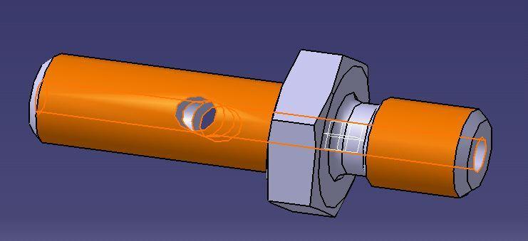
8 1.8 The final model 8
Part Design Fundamentals
 Part Design Fundamentals 1 Course Presentation Objectives of the course In this course you will learn basic methods to create and modify solids features and parts Targeted audience New CATIA V5 Users 1
Introduction to CATIA V5
 Introduction to CATIA V5 Release 17 (A Hands-On Tutorial Approach) Kirstie Plantenberg University of Detroit Mercy SDC PUBLICATIONS Schroff Development Corporation www.schroff.com Better Textbooks. Lower
Basic Features. In this lesson you will learn how to create basic CATIA features. Lesson Contents: CATIA V5 Fundamentals- Lesson 3: Basic Features
 Basic Features In this lesson you will learn how to create basic CATIA features. Lesson Contents: Case Study: Basic Features Design Intent Stages in the Process Determine a Suitable Base Feature Create
Advanced Modeling Techniques Sweep and Helical Sweep
 Advanced Modeling Techniques Sweep and Helical Sweep Sweep A sweep is a profile that follows a path placed on a datum. It is important when creating a sweep that the designer plans the size of the path
ME Week 2 Project 2 Flange Manifold Part
 1 Project 2 - Flange Manifold Part 1.1 Instructions This project focuses on additional sketching methods and sketching commands. Revolve and Work features are also introduced. The part being modeled is
Solidworks: Lesson 4 Assembly Basics and Toolbox. UCF Engineering
 Solidworks: Lesson 4 Assembly Basics and Toolbox UCF Engineering Solidworks We have now completed the basic features of part modeling and it is now time to begin constructing more complex models in the
M TE S Y S LT U A S S A
 Dress-Up Features In this lesson you will learn how to place dress-up features on parts. Lesson Contents: Case Study: Timing Chain Cover Design Intent Stages in the Process Apply a Draft Create a Stiffener
CATIA Instructor-led Live Online Training Program
 Course Outline Introduction & Understanding to CATIA Environment Introduction & Understanding to CATIA interface Starting new file Understand the Sketcher workbench of CATIA V5 Start a new file in the
DUE DATE: Friday 4/6/2018 at 3:30 PM
 MECH 130 SPRING 2018 CAD LAB 4 FINAL REVISION HARDCOPIES NEEDED DUE DATE: Friday 4/6/2018 at 3:30 PM After the revised hitch, the ball and the pin parts were created from the Handout call LAB4 PART Creation,
Feature-Based Modeling and Optional Advanced Modeling. ENGR 1182 SolidWorks 05
 Feature-Based Modeling and Optional Advanced Modeling ENGR 1182 SolidWorks 05 Today s Objectives Feature-Based Modeling (comprised of 2 sections as shown below) 1. Breaking it down into features Creating
Cube in a cube Fusion 360 tutorial
 Cube in a cube Fusion 360 tutorial n Before using these instructions, it is helpful to watch this video screencast of the CAD drawing actually being done in the software. Click to link to the video tutorial.
Using Siemens NX 11 Software. The connecting rod
 Using Siemens NX 11 Software The connecting rod Based on a Catia tutorial written by Loïc Stefanski. At the end of this manual, you should obtain the following part: 1 Introduction. Start NX 11 and open
Autodesk Inventor 2016 Creating Sketches
 Autodesk Inventor 2016 Creating Sketches 2D Sketch Practice 1 1. Launch Autodesk Inventor 2016 2. Create a new Part file (.ipt) 3. Save File As a. Click on the save icon. b. Save you file onto your flash
1. Create a 2D sketch 2. Create geometry in a sketch 3. Use constraints to position geometry 4. Use dimensions to set the size of geometry
 2.1: Sketching Many features that you create in Fusion 360 start with a 2D sketch. In order to create intelligent and predictable designs, a good understanding of how to create sketches and how to apply
MN Modelling Objects and Creating Manufacturing Strategy
 Abstract This document and the accompanying files describe the process of modelling a bell housing jig using the 3D software Catia V5. The manufacturing process by which the bell housing would be created
Nut and Bolt Tutorial
 Thread Representations Nut and Bolt Tutorial Parts to a Thread Thread Dimensioning Major Diameter Thread Series (IE UNC, UNF, ACME, etc) ½ - 13 UNC 2 A or B A = External B = Internal Threads per Inch Class
Objectives. Inventor Part Modeling MA 23-1 Presented by Tom Short, P.E. Munro & Associates, Inc
 Objectives Inventor Part Modeling MA 23-1 Presented by Tom Short, P.E. Munro & Associates, Inc To demonstrate most of the sketch tools and part features in : Inventor Release 6 And, to show logical techniques
Training Guide Basics
 Training Guide Basics 2014, Missler Software. 7, Rue du Bois Sauvage F-91055 Evry, FRANCE Web: www.topsolid.com E-mail: info@topsolid.com All rights reserved. TopSolid Design Basics This information is
Multiview Drawing. Definition: Graphical representation of a 3- dimensional object on one plane (sheet of paper) using two or more views.
 using two or more views.") Multiview Drawing Definition: Graphical representation of a 3- dimensional object on one plane (sheet of paper) using two or more views. Multiview Drawing Another name for multiview drawing is orthographic
Multiview Drawing Definition: Graphical representation of a 3- dimensional object on one plane (sheet of paper) using two or more views. Multiview Drawing Another name for multiview drawing is orthographic
SolidWorks Design & Technology
 SolidWorks Design & Technology Training Course at PHSG Ex 5. Lego man Working with part files 8mm At first glance the Lego man looks complicated but I hope you will see that if you approach a project one
LABORATORY MANUAL COMPUTER AIDED DESIGN LAB
 LABORATORY MANUAL COMPUTER AIDED DESIGN LAB Sr. No 1 2 3 Experiment Title Setting up of drawing environment by setting drawing limits, drawing units, naming the drawing, naming layers, setting line types
MODELING AND DESIGN C H A P T E R F O U R
 MODELING AND DESIGN C H A P T E R F O U R OBJECTIVES 1. Identify and specify basic geometric elements and primitive shapes. 2. Select a 2D profile that best describes the shape of an object. 3. Identify
Downloaded from ENGINEERING DRAWING. Time allowed : 3 hours Maximum Marks : 70
 ENGINEERING DRAWING Time allowed : 3 hours Maximum Marks : 70 Note : (i) (ii) Attempt all the questions. Use both sides of the drawing sheet, if necessary. (iii) All dimensions are in millimeters. (iv)
Graz University of Technology CATIA V5. Basic Training. CAx in Automotive and Engine Technology Dipl.-Ing. Dr.techn.
 CATIA V5 Basic Training CAx in Automotive and Engine Technology 313.067 Dipl.-Ing. Dr.techn. Michael Lang Preface The present script includes an introduction of the main features in the 3D design software
Sash Clamp. Sash Clamp SW 2015 Design & Communication Graphics Page 1.
 Sash Clamp 1 Introduction: The Sash clamp consists of nine parts. In creating the clamp we will be looking at the improvements made by SolidWorks in linear patterns, adding threads and in assembling the
J. La Favre Fusion 360 Lesson 2 April 19, 2017
 In this lesson, you will create a round plate with 12 counter-bored holes to fit 6-32 socket head screws. A counter-bored hole has two diameters, one to fit the threaded part of the screw and the other
CATIA LABSHEETS ZEIT 1501: Engineering Practice and Design. Dr. Hemant Kumar Singh Dr. Khairul Alam
 CATIA LABSHEETS ZEIT 1501: Engineering Practice and Design Dr. Hemant Kumar Singh Dr. Khairul Alam 2014 Important Information on CATIA Drawing Submissions: 2014 Please take note of the following: (a) (b)
SolidWorks Training. Introductory course for staff and students from the School of Physics and Astronomy
 SolidWorks Training Introductory course for staff and students from the School of Physics and Astronomy i) Introductory presentation SolidWorks Training ii) The SolidWorks GUI The SolidWorks Graphical
ENGINEERING GRAPHICS
 ENGINEERING GRAPHICS Time allowed : 3 hours Maximum Marks : 70 Note : (ii) Attempt all the questions. Use both sides of the drawing sheet, if necessary. (iii) All dimensions are in millimetres. (iv) Missing
11/12/2015 CHAPTER 7. Axonometric Drawings (cont.) Axonometric Drawings (cont.) Isometric Projections (cont.) 1) Axonometric Drawings
 Axonometric Drawings (cont.) Isometric Projections (cont.) 1) Axonometric Drawings") CHAPTER 7 1) Axonometric Drawings 1) Introduction Isometric & Oblique Projection Axonometric projection is a parallel projection technique used to create a pictorial drawing of an object by rotating the
CHAPTER 7 1) Axonometric Drawings 1) Introduction Isometric & Oblique Projection Axonometric projection is a parallel projection technique used to create a pictorial drawing of an object by rotating the
Dimensioning. Dimensions: Are required on detail drawings. Provide the shape, size and location description: ASME Dimensioning Standards
 Dimensioning Dimensions: Are required on detail drawings. Provide the shape, size and location description: - Size dimensions - Location dimensions - Notes Local notes (specific notes) General notes ASME
Activity Pegboard Toy
 Activity 1.5.5 Pegboard Toy Purpose When you receive a toy, what is the first thing you wonder about it? Do you wonder how it works? Have you ever wondered who designed it or who may have made decisions
Shaft Hanger - SolidWorks
 ME-430 INTRODUCTION TO COMPUTER AIDED DESIGN Shaft Hanger - SolidWorks BY: DR. HERLI SURJANHATA ASSIGNMENT Submit TWO isometric views of the Shaft Hanger with your report, 1. Shaded view of the trimetric
Education Curriculum Combined Specialist
 Education Curriculum Combined Specialist Invest your time in imagining next generation designs. Here s what we will teach you to give shape to your imagination. CATIA Combined Specialist Course CATIA Mechanical
Activity 5.2 Making Sketches in CAD
 Activity 5.2 Making Sketches in CAD Introduction It would be great if computer systems were advanced enough to take a mental image of an object, such as the thought of a sports car, and instantly generate
Activity 5.5a CAD Model Features Part 1
 Activity 5.5a CAD Model Features Part 1 Introduction In order to use CAD effectively as a design tool, the designer must have the skills necessary to create, edit, and manipulate a 3D model of a part in
Introduction to Circular Pattern Flower Pot
 Prerequisite Knowledge Previous knowledge of the sketching commands Line, Circle, Add Relations, Smart Dimension is required to complete this lesson. Previous examples of Revolved Boss/Base, Cut Extrude,
Software Development & Education Center NX 8.5 (CAD CAM CAE)
") Software Development & Education Center NX 8.5 (CAD CAM CAE) Detailed Curriculum Overview Intended Audience Course Objectives Prerequisites How to Use This Course Class Standards Part File Naming Seed
Software Development & Education Center NX 8.5 (CAD CAM CAE) Detailed Curriculum Overview Intended Audience Course Objectives Prerequisites How to Use This Course Class Standards Part File Naming Seed
Table of Contents. Dedication Preface. Chapter 1: Introduction to CATIA V5-6R2015. Chapter 2: Drawing Sketches in the Sketcher Workbench-I.
 Table of Contents Dedication Preface iii xvii Chapter 1: Introduction to CATIA V5-6R2015 Introduction to CATIA V5-6R2015 1-2 CATIA V5 Workbenches 1-2 System Requirements 1-4 Getting Started with CATIA
Engineering Technology
 Engineering Technology Introduction to Parametric Modelling Engineering Technology 1 See Saw Exercise Part 1 Base Commands used New Part This lesson includes Sketching, Extruded Boss/Base, Hole Wizard,
Beginner s Guide to SolidWorks Alejandro Reyes, MSME Certified SolidWorks Professional and Instructor SDC PUBLICATIONS
 Beginner s Guide to SolidWorks 2008 Alejandro Reyes, MSME Certified SolidWorks Professional and Instructor SDC PUBLICATIONS Schroff Development Corporation www.schroff.com www.schroff-europe.com Part Modeling
2012 Academic Challenge
 2012 Academic Challenge ENGINEERING GRAPHICS TEST STATE FINAL This Test Consists of 40 Questions Engineering Graphics Test Production Team Ryan Brown, Illinois State University Author/Team Leader Jacob
FUSION 360: SKETCHING FOR MAKERS
 FUSION 360: SKETCHING FOR MAKERS LaDeana Dockery 2017 MAKEICT Wichita, KS 1 Table of Contents Interface... 1 File Operations... 1 Opening Existing Models... 1 Mouse Navigation... 1 Preferences... 2 Navigation
Digital Camera Exercise
 Commands Used New Part This lesson includes Sketching, Extruded Boss/Base, Extruded Cut, Fillet, Chamfer and Text. Click File, New on the standard toolbar. Select Part from the New SolidWorks Document
Module 1H: Creating an Ellipse-Based Cylindrical Sheet-metal Lateral Piece
 Inventor (10) Module 1H: 1H- 1 Module 1H: Creating an Ellipse-Based Cylindrical Sheet-metal Lateral Piece In this Module, we will learn how to create an ellipse-based cylindrical sheetmetal lateral piece
Engineering & Computer Graphics Workbook Using SolidWorks 2014
 Engineering & Computer Graphics Workbook Using SolidWorks 2014 Ronald E. Barr Thomas J. Krueger Davor Juricic SDC PUBLICATIONS Better Textbooks. Lower Prices. www.sdcpublications.com Powered by TCPDF (www.tcpdf.org)
Engineering & Computer Graphics Workbook Using SOLIDWORKS
 Engineering & Computer Graphics Workbook Using SOLIDWORKS 2017 Ronald E. Barr Thomas J. Krueger Davor Juricic SDC PUBLICATIONS Better Textbooks. Lower Prices. www.sdcpublications.com Powered by TCPDF (www.tcpdf.org)
2010 Academic Challenge
 2010 Academic Challenge ENGINEERING GRAPHICS TEST STATE FINALS This Test Consists of 40 Questions Engineering Graphics Test Production Team Ryan K. Brown, Illinois State University Author/Team Leader Jacob
AEROPLANE. Create a New Folder in your chosen location called Aeroplane. The four parts that make up the project will be saved here.
 AEROPLANE Prerequisite Knowledge Previous knowledge of the following commands is required to complete this lesson. Sketching (Line, Rectangle, Arc, Add Relations, Dimensioning), Extrude, Assemblies and
Solid Part Four A Bracket Made by Mirroring
 C h a p t e r 5 Solid Part Four A Bracket Made by Mirroring This chapter will cover the following to World Class standards: Sketch of a Solid Problem Draw a Series of Lines Finish the 2D Sketch Extrude
2004 Academic Challenge
 2004 Academic Challenge ENGINEERING GRAPHICS TEST - REGIONAL Engineering Graphics Test Production Team Ryan Brown, Illinois State University Author/Team Coordinator Kevin Devine, Illinois State University
SolidWorks 95 User s Guide
 SolidWorks 95 User s Guide Disclaimer: The following User Guide was extracted from SolidWorks 95 Help files and was not originally distributed in this format. All content 1995, SolidWorks Corporation Contents
CAD & BSI Theory. Arbroath Academy - Technology Department - National 5 Graphic Communication
 CAD & BSI Theory These symbols are drawn from BSI. Building Drawing Symbols You may be required to use these symbols in your assignment or project, or be asked questions about them in your exam. You must
From the above fig. After sketching the path and profile select the sweep command First select the profile from property manager tree And then select
 Chapter 5 In sweep command there is a) Two sketch profiles b) Two path c) One sketch profile and one path The sweep profile is used to create threads springs circular things and difficult geometry. For
Pro/DESKTOP Tutorial Drafting Bow Compass
 Pro/DESKTOP Tutorial Drafting Bow Compass Michael Flowers 2005 1 Objectives: To develop confidence with the Pro/DESKTOP software. To learn to utilize extrude, project, revolve, round, and chamfer features.
Autodesk Inventor Module 17 Angles
 Inventor Self-paced ecourse Autodesk Inventor Module 17 Angles Learning Outcomes When you have completed this module, you will be able to: 1 Describe drawing inclined lines, aligned and angular dimensions,
Activity 4.5 Pegboard Toy
 Activity 4.5 Pegboard Toy Purpose When you receive a toy, what is the first thing you wonder about it? Do you wonder how it works? Sometimes when you received or bought a toy, did you ever wonder who designed
Introduction to Autodesk Inventor User Interface Student Manual MODEL WINDOW
 Emmett Wemp EDTECH 503 Introduction to Autodesk Inventor User Interface Fill in the blanks of the different tools available in the user interface of Autodesk Inventor as your instructor discusses them.
SolidWorks Part I - Basic Tools SDC. Includes. Parts, Assemblies and Drawings. Paul Tran CSWE, CSWI
 SolidWorks 2015 Part I - Basic Tools Includes CSWA Preparation Material Parts, Assemblies and Drawings Paul Tran CSWE, CSWI SDC PUBLICATIONS Better Textbooks. Lower Prices. www.sdcpublications.com Powered
Diane Burton, STEM Outreach.
 123D Design Tutorial: LED decoration Before using these instructions, it is very helpful to watch this video screencast of the CAD drawing actually being done in the software. Click this link for the video
ENGINEERING GRAPHICS CLASS - XII (046) DESIGN OF THE QUESTION PAPER
 DESIGN OF THE QUESTION PAPER") ENGINEERING GRAPHICS CLASS - XII (046) DESIGN OF THE QUESTION PAPER Time : 3 Hrs Max. Marks : 70 The weightage of the distribution of marks over different contents of the question paper shall be as follows:
ENGINEERING GRAPHICS CLASS - XII (046) DESIGN OF THE QUESTION PAPER Time : 3 Hrs Max. Marks : 70 The weightage of the distribution of marks over different contents of the question paper shall be as follows:
Chapter 2. Drawing Sketches for Solid Models. Learning Objectives
 Chapter 2 Drawing Sketches for Solid Models Learning Objectives After completing this chapter, you will be able to: Start a new template file to draw sketches. Set up the sketching environment. Use various
Lesson 10: Loft Features
 10 Goals of This Lesson Your students will be able to create the following part: profiles chisel This lesson plan corresponds to the Loft Features chapter of SolidWorks Getting Started. SolidWorks Student
Introduction to ANSYS DesignModeler
 Lecture 4 Planes and Sketches 14. 5 Release Introduction to ANSYS DesignModeler 2012 ANSYS, Inc. November 20, 2012 1 Release 14.5 Preprocessing Workflow Geometry Creation OR Geometry Import Geometry Operations
Sheet metal tutorial. To set the bend radius Right click on the first sheet metal icon in the command manager and specify a bend radius or 1mm.
 Sheet metal tutorial In the following tutorial you will cover the basic features of the Solid Works sheet metal tool by modelling the component shown opposite. Activating Sheet metal mode Sheet metal components
Introduction to Sheet Metal Features SolidWorks 2009
 SolidWorks 2009 Table of Contents Introduction to Sheet Metal Features Base Flange Method Magazine File.. 3 Envelopment & Development of Surfaces.. 14 Development of Transition Pieces.. 23 Conversion to
1. Open the Feature Modeling demo part file on the EEIC website. Ask student about which constraints needed to Fully Define.
 BLUE boxed notes are intended as aids to the lecturer RED boxed notes are comments that the lecturer could make Control + Click HERE to view enlarged IMAGE and Construction Strategy he following set of
2009 Academic Challenge
 2009 Academic Challenge ENGINEERING GRAPHICS TEST STATE FINALS This Test Consists of 50 Questions Engineering Graphics Test Production Team Ryan Brown, Illinois State University Author/Team Leader Kevin
Lesson 6 2D Sketch Panel Tools
 Lesson 6 2D Sketch Panel Tools Inventor s Sketch Tool Bar contains tools for creating the basic geometry to create features and parts. On the surface, the Geometry tools look fairly standard: line, circle,
Activity Pegboard Toy
 Activity 1.5.5 Pegboard Toy Purpose When you receive a toy, what is the first thing you wonder about it? Do you wonder how it works? Have you ever wondered who designed it or who may have made decisions
ENGINEERING GRAPHICS
 ENGINEERING GRAPHICS CLASS - XII (046) DESIGN OF THE QUESTION PAPER Time : 3 Hrs Max. Marks : 70 The weightage of the distribution of marks over different contents of the question paper shall be as follows:
Conversational Programming. Alexsys Operator Manual
 Conversational Programming Alexsys Operator Manual Alexsys Operator Manual 1. Overview ALEXSYS is a programming system for CNC machining centers. That combines features of CAD / CAM systems with typical
Assembly Receiver/Hitch/Ball/Pin to use for CAD LAB 5A and 5B:
 MECH 130 CAD LAB 5 SPRING 2017 due Friday, April 21, 2016 at 4:30 PM All of LAB 5 s hardcopies will be working drawing layouts. Do not print out from the part file. We will be using the ME130DRAW drawing
Unit 4: Geometric Construction (Chapter4: Geometry For Modeling and Design)
") Unit 4: Geometric Construction (Chapter4: Geometry For Modeling and Design) DFTG-1305 Technical Drafting Instructor: Jimmy Nhan OBJECTIVES 1. Identify and specify basic geometric elements and primitive
Unit 4: Geometric Construction (Chapter4: Geometry For Modeling and Design) DFTG-1305 Technical Drafting Instructor: Jimmy Nhan OBJECTIVES 1. Identify and specify basic geometric elements and primitive
Terms The definitions of 16 critical terms defined by the 2009 standard 1
 856 SALT LAKE COURT SAN JOSE, CA 95133 (408) 251 5329 Terms The definitions of 16 critical terms defined by the 2009 standard 1 The names and definitions of many GD&T terms have very specific meanings.
Module 1C: Adding Dovetail Seams to Curved Edges on A Flat Sheet-Metal Piece
 1 Module 1C: Adding Dovetail Seams to Curved Edges on A Flat Sheet-Metal Piece In this Module, we will explore the method of adding dovetail seams to curved edges such as the circumferential edge of a
Explanation of buttons used for sketching in Unigraphics
 Explanation of buttons used for sketching in Unigraphics Sketcher Tool Bar Finish Sketch is for exiting the Sketcher Task Environment. Sketch Name is the name of the current active sketch. You can also
CAD Mechanical Design I
 EXAM INFORMATION Items 58 Points 85 Prerequisites NONE Course Length ONE SEMESTER Career Cluster ARCHITECTURE AND CONSTRUCTION MANUFACTURING SCIENCE, TECHNOLOGY, ENGINEERING AND MATHEMATICS Performance
Teach Yourself UG NX Step-by-Step
 Teach Yourself UG NX Step-by-Step By Hui Zhang Ph.D., P.Eng. www.geocities.com/zhanghui1998 Table of Contents Chapter 1 Introduction... 1 1.1 UG NX User Interface... 1 1.2 Solid Modeling Fundamentals...
2003 Academic Challenge
 Worldwide Youth in Science and Engineering 2003 Academic Challenge ENGINEERING GRAPHICS TEST - REGIONAL Engineering Graphics Test Production Team Ryan Brown, Illinois State University Author/Team Coordinator
Introduction to Autodesk Inventor for F1 in Schools (Australian Version)
") Introduction to Autodesk Inventor for F1 in Schools (Australian Version) F1 in Schools race car In this course you will be introduced to Autodesk Inventor, which is the centerpiece of Autodesk s Digital
Introduction to Autodesk Inventor for F1 in Schools (Australian Version) F1 in Schools race car In this course you will be introduced to Autodesk Inventor, which is the centerpiece of Autodesk s Digital
Starting a 3D Modeling Part File
 1 How to Create a 3D Model and Corresponding 2D Drawing with Dimensions, GDT (Geometric Dimensioning and Tolerance) Symbols and Title Block in SolidWorks 2013-2014 By Edward Locke This tutorial will introduce
TECHNICAL DRAWING HIGHER LEVEL PAPER II(A) ENGINEERING APPLICATIONS
 ENGINEERING APPLICATIONS") M. 84 AN ROINN OIDEACHAIS AGUS EOLAÍOCHTA LEAVING CERTIFICATE EXAMINATION, 2001 TECHNICAL DRAWING HIGHER LEVEL PAPER II(A) ENGINEERING APPLICATIONS Friday, 15 June, Afternoon 2.00 5.00 p.m. 200 Marks INSTRUCTIONS
M. 84 AN ROINN OIDEACHAIS AGUS EOLAÍOCHTA LEAVING CERTIFICATE EXAMINATION, 2001 TECHNICAL DRAWING HIGHER LEVEL PAPER II(A) ENGINEERING APPLICATIONS Friday, 15 June, Afternoon 2.00 5.00 p.m. 200 Marks INSTRUCTIONS
Drawing and Assembling
 Youth Explore Trades Skills Description In this activity the six sides of a die will be drawn and then assembled together. The intent is to understand how constraints are used to lock individual parts
Rotational Patterns of Sketched Features Using Datum Planes On-The-Fly
 Rotational Patterns of Sketched Features Using Datum Planes On-The-Fly Patterning a sketched feature (such as a slot, rib, square, etc.,) requires a slightly different technique. Why can t we create a
Name: Date Completed: Basic Inventor Skills I
 Name: Date Completed: Basic Inventor Skills I 1. Sketch, dimension and extrude a basic shape i. Select New tab from toolbar. ii. Select Standard.ipt from dialogue box by double clicking on the icon. iii.
NX 7.5. Table of Contents. Lesson 3 More Features
 NX 7.5 Lesson 3 More Features Pre-reqs/Technical Skills Basic computer use Completion of NX 7.5 Lessons 1&2 Expectations Read lesson material Implement steps in software while reading through lesson material
ADA Curriculum for Pre-Engineering Students Correlation Guide
 ADA Curriculum for Pre-Engineering Students Correlation Guide Madsen/Autodesk Inventor 7: Basics Through Advanced Note: The concepts presented in the ADA Curriculum are covered in the text as they pertain
EXERCISE ONE: BEACH BUGGY.
 EXERCISE ONE: BEACH BUGGY. Prerequisite knowledge Students should have completed Exercises from the file: Introduction to Assemblies Concept Mates Focus of lesson Commands Used This lesson will focus on
ENGINEERING GRAPHICS
 ENGINEERING GRAPHICS Course Structure Units Topics Marks Unit I Plane Geometry 16 1 Lines, angles and rectilinear figures 2 Circles and tangents 3 Special curves: ellipse, parabola, involute, cycloid.
Siemens NX11 tutorials. The angled part
 Siemens NX11 tutorials The angled part Adaptation to NX 11 from notes from a seminar Drive-to-trial organized by IBM and GDTech. This tutorial will help you design the mechanical presented in the figure
International Journal of Scientific & Engineering Research, Volume 7, Issue 11, November ISSN HEAT EXCHANGER.
 International Journal of Scientific & Engineering Research, Volume 7, Issue 11, November-2016 577 HEAT EXCHANGER Hassan Alshaiki Table of contents Introduction 3 Designing the Heat Exchanger..4 Base Nut
Veerapandian.K Mechanical Engg Vedharanyam A manual to mechanical designers How Solid works Works?
 Compiled by Veerapandian.K Mechanical Engg Vedharanyam-614 810 A manual to mechanical designers How Solid works Works? Solid works Overview Solid works main idea is user to create drawing directly in 3D
Vocabulary. Cavalier oblique: An oblique drawing in which the depth axis lines are drawn at full scale (full size).
.") 10-11-11 Vocabulary Cavalier oblique: An oblique drawing in which the depth axis lines are drawn at full scale (full size). 10-12-11 Vocabulary Centerlines: Thin lines made up of long and short dashes
10-11-11 Vocabulary Cavalier oblique: An oblique drawing in which the depth axis lines are drawn at full scale (full size). 10-12-11 Vocabulary Centerlines: Thin lines made up of long and short dashes
CLASS views from detail on a grid paper. (use appropriate line types to show features) - Optional views. Turn in for grading on class 6 (06/04)
 - Optional views. Turn in for grading on class 6 (06/04)") CLASS 4 Review: - Projections - Orthographic projections Lab: - 3 views from detail on a grid paper. (use appropriate line types to show features) - Optional views. Turn in for grading on class 6 (06/04)
CLASS 4 Review: - Projections - Orthographic projections Lab: - 3 views from detail on a grid paper. (use appropriate line types to show features) - Optional views. Turn in for grading on class 6 (06/04)
Unit-5 ISOMETRIC PROJECTION
 Unit-5 ISOMETRIC PROJECTION Importance Points in Isometric: 1. For drawing the isometric, the object must be viewed such that either the front -right or the left edges becomes nearest. 2. All vertical
BOARD DIPLOMA EXAMINATION, (C 14) APRIL/MAY 2015 DECE FIRST YEAR EXAMINATION ENGINEERING DRAWING
 APRIL/MAY 2015 DECE FIRST YEAR EXAMINATION ENGINEERING DRAWING") C 14 CHPC/EC/PET 107 4037 BOARD DIPLOMA EXAMINATION, (C 14) APRIL/MAY 2015 DECE FIRST YEAR EXAMINATION ENGINEERING DRAWING Time : 3 hours ] [ Total Marks : 60 Instructions : (1) Answer all questions. PART
C 14 CHPC/EC/PET 107 4037 BOARD DIPLOMA EXAMINATION, (C 14) APRIL/MAY 2015 DECE FIRST YEAR EXAMINATION ENGINEERING DRAWING Time : 3 hours ] [ Total Marks : 60 Instructions : (1) Answer all questions. PART
Inventor-Parts-Tutorial By: Dor Ashur
 Inventor-Parts-Tutorial By: Dor Ashur For Assignment: http://www.maelabs.ucsd.edu/mae3/assignments/cad/inventor_parts.pdf Open Autodesk Inventor: Start-> All Programs -> Autodesk -> Autodesk Inventor 2010
Toothbrush Holder. A drawing of the sheet metal part will also be created.
 Prerequisite Knowledge Previous knowledge of the following commands is required to complete this lesson; Sketch (Line, Centerline, Circle, Add Relations, Smart Dimension,), Extrude Boss/Base, and Edit